
Related Manuals for Trane FADA


Summary of Contents for Trane FADA
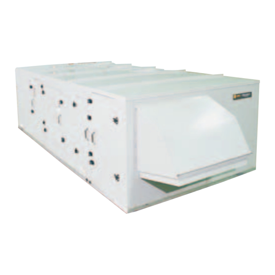
- Page 1 Installation, Operation, and Maintenance Packaged Fresh Air Unit For 100% Outdoor Air Applications Models FADA and FAHA “BO” and later design sequence FAXA-SVX01B-EN April 2003...
-
Page 2: About This Manual
CV = constant volume Use this manual for Packaged Fresh Air CW = clockwise units, models FADA and FAHA. This is the CCW = counterclockwise Warnings and Cautions “B” issue of this manual, revised to E/A = exhaust air include the total energy wheel option. -
Page 3: Table Of Contents
contents Cross reference to related publications: • Packaged Fresh Air Unit Programming Guide, FAXA-SVP01B-EN • Accessory Roof Curb Installation Manual, FAXA-SVN01B-EN • Reznor Installation Form RGM 401, Installation/Operation/Service for units with gas heat Installation ……………………………………………………………2 General Information……………………………………………2 Pre-installation Considerations ………………………………8 Dimensions/Weights …………………………………………15 Mechanical Requirements …………………………………33 Electrical Requirements………………………………………36... -
Page 4: Installation
general Installation information Packaged Fresh Air unit Model Number Description Following is a complete description of the Packaged FAU model number. Each digit in the model number has a corresponding code that identifies specific unit options. F A D A 040 6 G A,0 0,8,4 0 1 A 0 1 A 0,5,7 0,7 A 0 0 0 E F 0 1... - Page 5 general Installation information Digits 37, 38 – Exhaust air fan horsepower F = zone dehumidification with OA RH 00 = none reference 01 = 1 G= supply air temperature control (no 02 = 2 dehumidification) 03 = 3 J = zone temperature control (no 05 = 5 dehumidification) 07 = 7.5...
- Page 6 general Installation information Packaged Fresh Air unit Accessory Model Number Description Following is a complete description of the Packaged FAU accessory model number. Each digit in the model number has a corresponding code that identifies specific accessory options. 5, 6, 7 10,11 23 24 Digit 1 –...
-
Page 7: Unit Nameplate
general Installation information Unit Nameplate The unit nameplate identifies the unit model number, appropriate service literature, and wiring diagram numbers. It is mounted on the control panel door. Reference this information when making inquiries or ordering parts or literature for the fresh air unit. -
Page 8: Pre-Installation Considerations
pre-installation Installation Installation considerations Pre-Installation Considerations Note: Verify electric stub-out within roof curb assembly, if using bottom electrical Checklist knockouts. The following checklist is provided to give an overview of the factory- recommended pre-installation o Electrical supply power must meet considerations. - Page 9 Visually inspect the unit exterior for inspection of the damage by the physical signs of shipping damage or carrier and consignee. o Notify your Trane representative of material shortages. o If a unit appears damaged, inspect it the damage and arrange for repair.
-
Page 10: Service Access
pre-installation Installation considerations Service Access unit without TE wheel Maintain adequate clearances around service access and above the fresh air unit to ensure for removal of proper unit operation and allow sufficient gas or electric service access. See Figure I-PC-1 for heaters recommended clearances. - Page 11 6. Align side rail (6) next to side rail (5) support (25) without flanges. Place the and attach crossmember (11) Note: Trane has a roof curb specifically clearance holes in the corner angle perpendicular to both side rails at the designed for the Packaged Fresh Air unit toward the top of the curb.
- Page 12 pre-installation Installation considerations Standard roof curb assembly, Curb legend units without TE wheel option (1) end rail (R/A end) (13) duct support end rail (2) end rail (S/A end) (14) duct support end rail (R/A end) (3) side rail (15) duct support side rail (R/A end) (4) side rail (16) duct support side rail (E/A end) (5) side rail...
- Page 13 pre-installation Installation considerations nt Layout Standard roof curb assembly, urb legend units with the TE wheel (1) end rail (R/A, E/A end) (15) duct support end rail (2) end rail (S/A end) (16) duct support side rail (R/A end) (3) side rail (17) duct support side rail (R/A end) (4) side rail (18) duct support side rail (E/A end)
-
Page 14: Installation Preparation
pre-installation Installation Installation considerations Acoustic Considerations Installation Preparation Before determining the final unit Before installing the unit, perform the installation site, remember that proper following procedures to ensure proper unit placement is critical in reducing unit operation. transmitting sound levels to the building. The ideal time to make provisions to 1. -
Page 15: Dimensions/Weights
dimensions Installation & weights Typical exterior dimensions, outdoor side view, unit without total energy wheel ft./in. outdoor side view, unit with total energy wheel detail B lifting hole detail A CONTROL PANEL END VIEW inlet hood end view control panel end view unit size without TE wheel 031, 041... - Page 16 dimensions Installation & weights unit without TE wheel - indoor side view (electric heat version shown) unit with TE wheel - indoor side view (electric heat version shown) single & dual gas heater options FAXA-SVX01B-EN...
- Page 17 dimensions Installation & weights Unit base plan view, duct openings & thru-base power openings, unit sizes 031 & 040 unit without TE wheel unit with TE wheel FAXA-SVX01B-EN...
- Page 18 dimensions Installation & weights Unit base plan view, duct openings & thru-base power openings, unit sizes 051 & 066 unit without TE wheel unit with TE wheel FAXA-SVX01B-EN...
- Page 19 dimensions Installation & weights Fresh air unit control panel detail, all unit sizes detail A THRU-BASE MAIN POWER WIRING ENTRANCE HOLE Ø3.000’’ NOTE: DRILL OR PUNCH HOLE IN COVER PLATE FOR SMALLER CONDUIT CONNECTION top view FAXA-SVX01B-EN...
- Page 20 dimensions Installation & weights Exterior features for unit sizes 031 & 040, without TE wheel CONDENSER FANS CONVENIENCE OUTLET (OPTION) LIFTING HOLES HORIZONTAL DISCHARGE MAIN COMPRESSOR ACCESS PANEL (OPTION) (40x35) MAIN CONDENSER HUMAN INTERFACE REHEAT COMPRESSOR/COIL ACCESS PANEL COIL ACCESS ACCESS DOOR (34x36) PANEL...
- Page 21 dimensions Installation & weights Exterior features, unit sizes 031 & 040 with TE wheel FAXA-SVX01B-EN...
- Page 22 dimensions Installation & weights Exterior features for unit sizes 051 & 066, without TE wheel CONDENSER FANS LIFTING HOLES REHEAT COMPRESSOR/ HORIZONTAL DISCHARGE COIL ACCESS PANEL (40x52) (OPTION) HUMAN INTERFACE ACCESS DOOR MAIN COMPRESSOR/ MAIN COMPRESSOR/ COIL ACCESS PANEL COIL ACCESS PANEL (34x52) UNIT CONTROL PANEL (68x52) CONVENIENCE OUTLET...
- Page 23 dimensions Installation & weights Exterior features for unit sizes 051 & 066 with TE wheel FAXA-SVX01B-EN...
- Page 24 dimensions Installation & weights Standard curb, unit sizes 031 & 040 without TE wheel 6’’ WOOD NAILER FAXA-SVX01B-EN...
- Page 25 dimensions Installation & weights Standard roof curb, unit sizes 031 & 040 with TE wheel 6" WOOD NAILER FAXA-SVX01B-EN...
- Page 26 dimensions Installation & weights Standard curb , unit sizes 051 & 66 without TE wheel 6’’ WOOD NAILER FAXA-SVX01B-EN...
- Page 27 dimensions Installation & weights Standard roof curb, unit sizes 051 & 066 with TE wheel 6" WOOD NAILER FAXA-SVX01B-EN...
- Page 28 dimensions Installation & weights Extended height roof curb, unit sizes 031 & 040 without TE wheel 6’’ WOOD NAILER FAXA-SVX01B-EN...
- Page 29 dimensions Installation & weights Extended height roof curb , unit sizes 031 & 040 with TE wheel 6" WOOD NAILER FAXA-SVX01B-EN...
- Page 30 dimensions Installation & weights Extended height roof curb, unit sizes 051 & 066 without TE wheel 6’’ WOOD NAILER FAXA-SVX01B-EN...
- Page 31 dimensions Installation & weights Extended height roof curb, unit sizes 051 & 066 with TE wheel 6" WOOD NAILER FAXA-SVX01B-EN...
- Page 32 dimensions Installation & weights Unit and accessory weights Table I-DW-1. Typical unit, unit with total energy wheel, and roof curb weights unit base unit total energy wheel unit roof curb for unit w/o TE wheel roof curb for unit with TE wheel size weight base weight...
-
Page 33: Mechanical Requirements
GROUND JOINT UNION 90B). Make duct connections to the curb with a flexible material such as heavy canvas. If a fire hazard exists, Trane recommends TO CONTROLS using Flexweave 1000, type FW30 or 3" (76 MM) equivalent canvas. Use three inches for PLUGGED 1/8"... - Page 34 mechanical Installation requirements 5. Pipe directly in to the manual shutoff WARNING valve. 6. Install a " (3.2 mm) N.P .T. plugged Explosion hazard! tapping, accessible for test gauge Failure to follow recommended safe connection, immediately upstream of leak test procedures can cause death the gas supply connection to the or serious injury.
-
Page 35: Mechanical Requirements
mechanical Installation requirements Condensate Drain Trapping A fresh air unit is selected for its dehumidifying capability. As such, condensate can be formed at an enormous rate. The Packaged Fresh Air Unit, drain pan and condensate line have been sized and designed accordingly. An often-overlooked element of proper condensate drainage is trapping. -
Page 36: Installation Requirements
electrical Installation requirements Electrical Requirements Table I-ER-1. Electrical service sizing data Follow these guidelines, referring to unit unit reheat comp (A) main comp 1 (B) main comp 2 (C) main comp 3 (D) wiring diagrams and supply power size voltage tons* rla tons* tons* tons*... - Page 37 electrical Installation requirements Power Wire Sizing and equal to or larger than the DSS value DSS = 1.15 x (load 1 + load 2 + load 3 + Protection Device Equations calculated. load 4) Set #2: Units with electric heat, single Select the DSS value that is the larger of Each type of unit has its own set of source power, non-concurrent load...
- Page 38 electrical Installation requirements rating equal to the MOP value. If the MOP For the calculations of MCA1 and MOP1, value does not equal a standard device use the instructions from set #1 size as listed in NEC 240-6, select the previously in this section.
- Page 39 electrical Installation requirements Table I-ER-9. Electric heat FLA unit size voltage 208/60/3 55.5 72.2 88.8 116.6 155.4 — — — — 230/60/3 48.1 62.5 77.0 101.0 134.7 — — — — 460/60/3 24.1 31.3 38.5 50.5 67.4 — — — —...
-
Page 40: Installation Procedure
installation Installation procedure Rigging and Placement equipment operates properly and the unit is properly balanced. Before Rigging and Lifting the Unit 4. Lift the unit and position it over the roof 1. Verify the roof curb is installed properly curb. Align the unit base rails with the and has the prooper gaskets installed roof curb. - Page 41 installation Installation procedure Rigging Procedure 1. Use spreader bars as shown in Figures I-IP-2 and I-IP-3 to prevent upper cabinet LIFTING POINT A MUST BE damage. If possible, use chains or ALIGNED DIRECTLY OVER UNIT 7 FT. MINIMUM: 7 FT. MINIMUM: CENER OF BALANCE FOR A SHORTER LENGTHS cables at lifting locations.
-
Page 42: Installation Procedure
installation Installation procedure Exhaust Louver Installation Install the exhaust louvers after installing the unit in its final position, following the procedure below. 1. Remove the temporary shipping panel from the exhaust exit. 2. Locate the shipped-with gravity damper in the main filter compartment. A ship-with item label indicates the door. -
Page 43: Wiring Guidelines
installation Installation procedure Zone Sensor Installation for Note: Guidelines for wire sizes and Temperature and Humidity lengths are shown in Table I-IP-1. The total resistance of these low voltage All remote sensor options ship in the wires must not exceed 2.5 ohms per return-air filter section, and require field- conductor. - Page 44 installation Installation procedure Figure I-IP-3. Zone sensor mounting hole locations. Wall Mounting Mounting to Junction Box Junction Figure I-IP-4. Typical zone sensor installation. FAXA-SVX01B-EN...
-
Page 45: Time Clock Option
installation Installation procedure Time Clock Option 4. Since all electronic instruments are sensitive to voltage spikes, pay close The time clock option has a attention to the following: programmable timer that is factory wired a. If possible, supply power to the to the unoccupied input to provide on/off electronic time clock from a phase control. - Page 46 installation Installation procedure Remote Human Interface Panel Installation Human Interface (HI) Panel The HI enables the user to communicate necessary unit operating parameters and receive operating status information from within the occupied space. The HI displays top level information in the LCD window, unless the operator initiates other displays, for the various unit functions.
- Page 47 installation Installation procedure Mounting the Remote Human e. Carefully slide the key pad plate d. Slide the extruded hinge pin at the top Interface (RHI) Panel upward from the bottom, releasing the left of the door into the hole located extruded hinge pin from its socket at under the bottom left side of the The installer must provide all mounting...
- Page 48 installation Installation procedure Figure I-IP-7. Remote HI mounting holes and knockout locations FAXA-SVX01B-EN...
-
Page 49: Wiring The Remote Human Interface
installation Installation procedure Wiring the Remote Human Low Voltage (AC) Field Wiring Note: Although the 24 volt power is not Interface polarity sensitive, do not connect either Connections To access the wire entry locations, open the + (plus) or - (minus) terminals from The remote human interface requires 24 the remote panel to ground at the fresh the RHI panel door and remove the two... -
Page 50: Installation Checklist
Packaged fresh air units can operate with evaporator condensate drain Trane building automation software, connection. Refer to Figure I-MR-2 on Tracer Summit version 14.0 or later. page 35. -
Page 51: Pre-Startup Requirements
pre-startup Installation requirements Pre-Startup Checklist Component Overview qVerify all fan and motor sheaves are Complete this checklist after installing the aligned. unit to verify all recommended qCheck all belt tensions are properly installation procedures are complete adjusted. before unit startup. This does not replace qEnsure all fans rotate freely. -
Page 52: Startup
Installation startup Unit Startup Procedures Follow the procedure below: 1. With the wheel stopped, move seals as 1. Check all electrical connections for close to the sealing surface as possible tightness. but without exceeding grip range of 2. Be sure all system components are bulb seal and without pressing the bulb properly set and installed. -
Page 53: Unit Startup
general Installation information startup 5. Check amp draw at compressor To ensure that Tracer Summit has no terminals. RLA and LRA is on the unit affect on unit operation, remove Tracer nameplate. wiring and make required changes to 6. Measure amp draw at evaporator and setpoint and sensor sources. - Page 54 Installation startup Unit Performance Log Compressor on or off? o on o off Complete this log at unit startup. D or NA model #______________________________ ____ ____ ____ ____ circuit 1 circuit 2 serial #______________________________ compressor compressor amps date_________________________________ job name_____________________________ ______________________________________ Key options: o hot gas condenser reheat...
- Page 55 general Installation information startup Gas heat Electric heat single or dual bank ____________ heater kW ____________ staged or modulating ____________ heater stages installed ____________ heater starts and runs? heater stages tested ____________ o yes o no heater amp draw as tested: comb.
-
Page 56: Operation
Packaged Fresh Air Units with Controls Available Input and Output Points Base • unoccupied economizer enable/disable We have designed the Trane Packaged Unit (RTM module on all units) • economizer minimum position Fresh Air unit with the latest control Binary inputs •... - Page 57 This allows the operator/servicer to diagnose the failure root cause. All setup parameters are Figure O-GI-1. The human interface panel on the Trane Packaged Fresh Air unit preset from the factory, requiring less startup time. IntelliPak Unit Features •...
- Page 58 general Operation information Optional Zone Sensors Standard With All Units Dual setpoint, manual/automatic Dual setpoint, manual/automatic BAYSENS017 zone temperature sensor, changeover sensor with system function changeover sensor, accessory model accessory model number digit 16 = A lights, accessory model number number digit 20 = A This wall-mounted zone sensor ships digit 21 = A...
- Page 59 general Operation information Integrated Comfort™ Systems Sensors for FAU Applications Zone temperature sensor w/timed Zone temperature sensor w/timed override buttons, accessory model override buttons and local setpoint number digit 17 = A, BAYSENS013 adjustment, accessory model number digit 18 = A, BAYSENS014 This zone sensor is for use with cooling/ This zone sensor is for use with cooling/ heating Integrated Comfort™...
-
Page 60: Fresh Air Unit Functions
general Operation information Overview 3. Directly to a single space and control the space temperature directly. For example, Fresh Air Unit Functions this application will provide temperature The Packaged Fresh Air Unit (FAU) control of a hotel hallway and ventilation provides conditioned outdoor air suitable of the adjacent rooms. -
Page 61: Packaged Fau Operation
general Operation information It’s important to remember that airside and reheat coils. Air leaves the evaporator economizer capability can be lost if coil saturated at the preset dew point dedicated outdoor air systems are sized condition (h2) and is reheated by the for minimum ventilation air only. -
Page 62: Fau Without Reheat
general Operation information FAU Without Reheat Figure O-GI-10 shows the Packaged FAU DX system, using a refrigerant circuit design without reheat. Dehumidification (Drying) Dehumidification Consider Figure O-GI-8. If the outdoor air dew point or zone RH is above the drying setpoint, the FAU will dehumidify the outdoor air. -
Page 63: Establishing Capacity Requirements
For more detailed information usually most straightforward to size the on this subject, see the Trane Packaged FAU to handle the entire latent load on the Fresh Air Unit catalog, MUA-PRC004-EN . -
Page 64: Sequence Of Operation
One way to control an energy recovery (default setpoint 45°F) wheel section. With Trane Packaged device is to turn it on and off with the • outside air temperature is above the FAU energy wheels, the exhaust air FAU system exhaust fan. - Page 65 sequence of Operation operation Supply Air Dehumidification supply air heating setpoint. The supply air Unit heating setpoint can be reset up based on Unoccupied Sequence HI selectable parameters (OA sensor, In unoccupied mode, the fan is stopped zone sensor if installed). The supply air and the OA damper is closed.
- Page 66 sequence of Operation operation Zone Dehumidification Unit Heating Sequence ventilation air to the space. Upon entering Sequence of Operation When not in drying mode, the unit will the occupied mode, the outside air stage heating capacity to maintain the damper opens and the supply air fan supply air heating setpoint.
- Page 67 sequence of Operation operation the occupied mode, the outside air damper opens and the supply air fan Unoccupied Sequence Unoccupied Sequence starts. When the return air damper option is In unoccupied mode, the fan stops and installed and a request for unoccupied Cooling Sequence the OA damper closes.
- Page 68 sequence of Operation operation UNIT OFF sequence “A” PURGE sequence “E” energy. The demand limit definition is When complete system shut down is This sequence uses supply air control for user definable at the human interface required, the following sequence is used. smoke control.
- Page 69 sequence of Operation operation Timed Override Activation - Non-ICS field-provided switch or contacts to This function is active whenever the user immediately shutdown all unit functions. selects the unit’s RTM module board as Total Energy Wheel with Occupancy the zone temperature source (can be set Control at the human interface panel).
-
Page 70: Maintenance
general Maintenance information Component arrangement unit size 031 & 040 unit without TE wheel unit with TE wheel FAXA-SVX01B-EN... - Page 71 general Maintenance information Component arrangement unit size 051 & 066 unit without TE wheel unit with TE wheel FAXA-SVX01B-EN...
- Page 72 general Maintenance information Total energy wheel cassette locations, typical indoor side views unit size 031 unit size 040 unit size 051 unit size 066 FAXA-SVX01B-EN...
- Page 73 general Maintenance information Table M-GI-1. Maintenace general data Unit size nominal cfm 3100 4000 5100 6600 maximum design cfm 3100 4000 5100 6600 minimum design cfm 1800 2200 2900 3600 Compressor data reheat circuit (nom. tons R134a) 3.0T 4.5T 6.2T 6.2T main circuit (nom.
-
Page 74: Maintenance Procedures
maintenance Maintenance procedures Maintenance Procedures Periodic Maintenance Procedures Coil Cleaning Procedure This section describes specific 1. Turn off gas supply to the gas heaters Before beginning any maintenance maintenance procedures that must be and disconnect power to the unit. procedures heed all warnings and preformed as a part of the normal 2. - Page 75 Cleaning the Total Energy Wheel solutions. If microbial growth is evident in Clean the total energy wheel as neces- Trane total energy wheels are self- the drain pan, remove and clean it sary to maintain optimum airflow. When cleaning with respect to dry particles.
- Page 76 maintenance Maintenance procedures putting the system back into service. Fan and Drive parallel to each other for maximum belt 8. Determine and correct the cause of Perform the following procedures and bearing life. Shim as necessary any microbial contamination. according to the “Periodic Maintenance under the motor or fan bearings to 9.
- Page 77 maintenance Maintenance procedures Adjusting Fan Belt Tension unit and open the supply fan access door. To adjust the fan belt tension, refer to The belt tension label is on the top right- Figure M-MP-6, following the procedure hand corner of the fan scroll. The correct below.
-
Page 78: Refrigerant System
Trane air above atmostpheric pressure stratospheric ozone layer when released recommends clean up methods using to the atmosphere. In particular, several because they may become flammable filters and dryers. - Page 79 Never pressurize the for POE, oil type. Oil type is different for unit above 200 psig. Trane compressors vs. Copeland 5. Retest the system to make sure new Charging the Refrigerant System compressors. Failure to comply may connections are solid.
-
Page 80: Periodic Checklists
periodic Maintenance checklists Periodic Maintenance 5. Check and record operating pressures Checklists 6. Inspect and clean total energy wheel as needed. Monthly Checklist Semi-Annual Maintenance The following checklist provides the 1. Verify the fan motor is properly aligned recommended maintenance schedule to and bolted tight to the motor frame. -
Page 81: System Checks
maintenance Maintenance procedures System Checks Operating Procedures systems can cause motor overheating Install pressure gauges on the discharge and premature failure. Maximum Before proceeding with technical trouble and suction line access valves. When the allowable imbalance is 2.0% and the charts or controls checkout, complete the unit has stabilized (after operating readings used to determine it must be... -
Page 82: Index
index roof curb installation 11 roof support 11 about this manual 2 heating 58 acoustic considerations 14 human interface (HI) panel 46, 49 acronyms 2 service access 10, 11 adjusting fan belt tension 74 ship-separate accessories 8 air filters 72 installation checklist 50 shipping package 8 airside economizers 58... - Page 84 LaCrosse - Inland www.trane.com For more information contact your local office or e-mail comfort@trane.com Trane has a policy of continuous product improvement and reserves the right to change design and specifica- tions without notice. Only qualified technicians should install and service equipment.
Need help?
Do you have a question about the FADA and is the answer not in the manual?
Questions and answers