Advertisement
Quick Links
IMPORTANT SAFETY INFORMATION: Always read this manual first
before attempting to install or use this device. For your safety, always
comply with all warnings and safety instructions contained in this manual
to prevent personal injury or property damage.
To view the full line of Dimplex products, please visit
www.dimplex.com
Owner's Manual
Model
WRCPF-KIT
7209110100R03
Advertisement

Related Manuals for Dimplex WRCPF-KIT


Summary of Contents for Dimplex WRCPF-KIT
- Page 1 For your safety, always comply with all warnings and safety instructions contained in this manual to prevent personal injury or property damage. To view the full line of Dimplex products, please visit www.dimplex.com 7209110100R03...
-
Page 2: Table Of Contents
CAUTION: Procedures and techniques which, if not carefully followed, will result in damage to the equipment. W ARNINg: Procedures and techniques which, if not carefully followed, will expose the user to the risk of fire, serious injury, or death. www.dimplex.com... -
Page 3: Welcome & Congratulations
Welcome & Congratulations Thank you and congratulations for choosing to purchase a Wall Switch Remote Control Kit from Dimplex, the world leader in electric fireplaces. Please carefully read and save these instructions. CAUTION: Read all instructions and warnings carefully before starting installation. -
Page 4: Product Overview
NOTE: This equipment has been Kit is designed to work with tested and found to comply with the limits for Class B digital device, the following Dimplex electric pursuant to part 15 of the FCC Rules. fireplaces: These limits are designed to provide reasonable protection against harmful •... -
Page 5: Receiver Installation (Bf Units Only)
Receiver Installation (BF units only) Open steel curtain (remove Figure 2 glass doors if applicable). ember Back Remove two (2) screws on log ledge grate and remove log grate (Figure 1). Rear Figure 1 Front Side section edge Locate and remove the two (2) screws on the manual control bracket (Figure 3). - Page 6 Install the two (2) screws removed in step 4 into the remote control bracket and attach it to the fireplace. Replace the log set by inserting front edge and pushing the back down until rear tab snaps under back www.dimplex.com...
-
Page 7: Wall Control Installation
Wall Control Installation ! NOTE: All electrical wiring available 24V~ power source must comply with all national should be considered. and local electrical codes WARNINg: Electrocution or and regulations. Always other bodily harm and property use a qualified and licensed damage can occur if a live electrician should you have wire is touched or damaged... - Page 8 Outer Housing. Push the Controller in until you hear the push- lock latches click (Figure 8). 6. Slide the Controller and Outer Housing assembly into a standard device box and Battery fasten with the two (2) flat Compartment www.dimplex.com...
- Page 9 Wall Control Installation to complete the installation Figure 8 and to blend the installation in Tracks with your choice of decor. Controller Hard Wired Power Supplied Installation Before starting this installation, it is helpful to initialize the Wall Switch Remote Control with your firebox (see Initialization section).
- Page 10 7. Gently pull the wire leads through while pushing the Controller into the Outer Housing until you hear the push 4. Uncoil the two wire leads and lock latches click, locking the feed each of them through one Controller in place (Figure 13). www.dimplex.com...
- Page 11 Wall Control Installation Locking Screw Option (Figure 14) Figure 12 Outer Housing To prevent tampering, damage, and theft, it is suggested to install the locking screws. Once installed, the locking screws will prevent the Controller from being released from the Outer Housing without being removed first from the device box in the wall.
- Page 12 Wall Control Installation Figure 15 Ensure each of the two Controller lead wires are connected to separate Low Voltage 24V~ only wires. Low Voltage Controller 24V~ power source ONLY wire leads Figure 16 Flat Head Screws (supplied) www.dimplex.com...
- Page 13 Wall Control Installation ! NOTE: Wire leads are not polarized due to the nature of this device. 9. Coil excess wiring to the back of the device box and insert the Controller and Outer Housing into the device box (Figure 16). Fasten with two supplied flat head screws.
-
Page 14: Initialization
(Figure 17-A) for five (5) seconds. The Level 1 6. Press any button on the Wall Indicator Light (Figure 17-D) Switch Remote Control within will then flash for 10 seconds. that 10 seconds. www.dimplex.com... -
Page 15: Operation
Initialization DF3033ST and DFg3033 Models 3. Set the 3 Position Manual Control (Figure 19B) to the 1. Ensure that power is supplied Remote position (left position). through main service panel. 4. Press and hold the 2. Ensure the Main On/Off Switch Initialization Button on the unit located in the switch box on (Figure... - Page 16 Pressing this button at any time that the LED is turned off is will shut the unit off. when the thermostat is set to “Heat Off”. C. Manual Selection Switch Switches the operation of the fireplace between the different modes of the fireplace: www.dimplex.com...
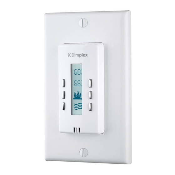
- Page 17 Operation Wall Switch Remote Control Display Operation 1. Room Temperature 8. Set Temperature Down 2. Set Temperature 9. Set Temperature Up 3. Flame Effect 10. Flame Off 4. Purifire™ 11. Flame On 5. Heat Off Indicator 12. Purifire™ Off 6. Function Lock Indicator 13. Purifire™ On 7.
- Page 18 8, 9 and 10 sequentially on. Press 13 to turn the Purifire™ again. The Indicator icon will be function on, and press 12 to turn displayed when enabled. Purifire™ off. ! NOTE: The Purifire™ function on this device will control only www.dimplex.com...
-
Page 19: Other Functions
Operation Other Functions 7. RF Code Function and Change Procedure 6 Hour Sleep Timer In the event that the Wall Switch This feature ensures all functions Remote Control does not work are turned off six hours after any properly with the receiver due last button has been pressed. -
Page 20: Warranty
Dimplex. It is agreed that in violation of the instruction sheet. This such repair or replacement is the exclusive...
Need help?
Do you have a question about the WRCPF-KIT and is the answer not in the manual?
Questions and answers