Table of Contents
Advertisement
Advertisement
Table of Contents

Related Manuals for DigiDesign 192 I/O


Summary of Contents for DigiDesign 192 I/O
- Page 1 192 I/O ™ Version 8.0...
- Page 2 Digidesign. This equipment has been tested to comply with the limits for a 003, 96 I/O, 96i I/O, 192 Digital I/O, 192 I/O, 888|24 I/O, Class A digital device. Changes or modifications to this 882|20 I/O, 1622 I/O, 24-Bit ADAT Bridge I/O, AudioSuite, 192 I/O not authorized by Digidesign, Inc., could void the...
-
Page 3: Table Of Contents
About www.digidesign.com ........ - Page 4 192 I/O Guide...
-
Page 5: Chapter 1. Introduction To The 192 I/O
TDIF. • External Clock input and output for synchro- The 192 I/O features 24-bit analog-to-digital nizing 192 I/O with external 1x Word Clock (A/D) and digital-to-analog (D/A) converters, or 256x (Slave Clock) devices. and supports sample rates of up to 192 kHz. -
Page 6: System Requirements And Compatibility Information
Conventions Used in This Guide System Requirements and All Digidesign guides use the following conven- Compatibility Information tions to indicate menu choices and key The Digidesign 192 I/O requires a Digidesign- commands: qualified Pro Tools|HD system. Convention Action Digidesign can only assure compatibility and File >... -
Page 7: About Www.digidesign.com
Development Partners and their plug- ins, applications, and hardware. News and Events Get the latest news from Digidesign or sign up for a Pro Tools demo. Pro Tools Accelerated Videos Watch the series of free tutorial videos. Accelerated Videos are de- signed to help you get up and running with Pro Tools and its plug-ins. - Page 8 192 I/O Guide...
-
Page 9: Chapter 2. 192 I/O Overview
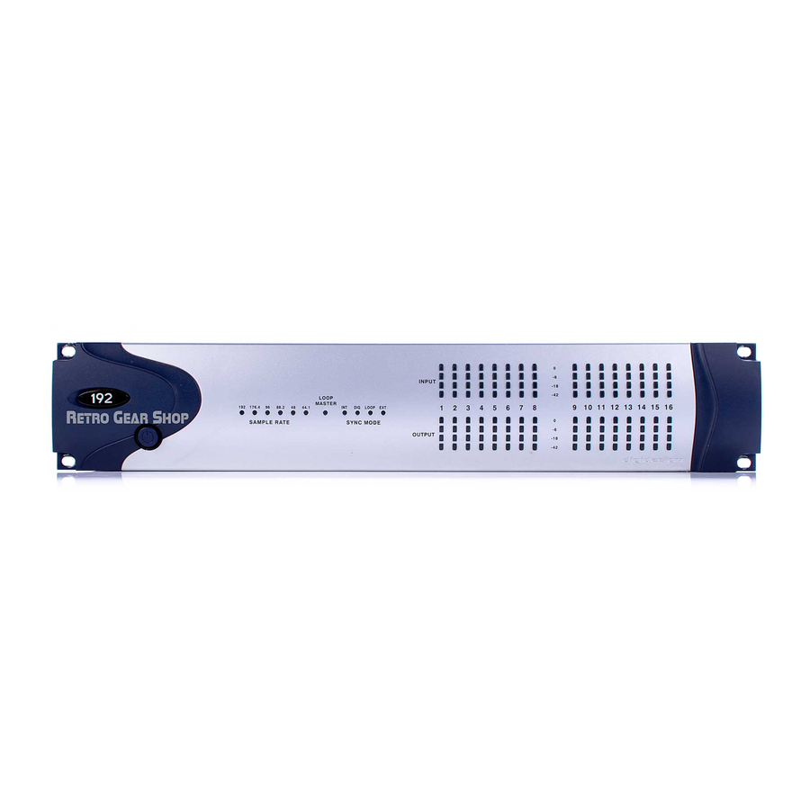
This chapter describes the front and back panel features of the 192 I/O. See the HD Setup Guide for complete system installation and configuration instructions. If you are adding the 192 I/O to an existing system, see the Expanded Systems Guide . 192 I/O Front Panel... - Page 10 However, for sample rates Pro Tools peripheral. The Loop Master LED will higher than 48 kHz, the 192 I/O will generate a be continuously lit on the current Loop Master choice of 1x or a base rate of 44.1 kHz or 48 kHz,...
-
Page 11: 192 I/O Back Panel
192 I/O Back Panel The 192 I/O has the following back panel features: Bay 3: Digital I/O card Enclosure Bay 1: Analog In card Empty Bay for Optional card Bay 2: Analog Out card 192 I/O Back Panel Although the 192 I/O is a 16-channel audio... - Page 12 See “Input Trims” on and supports 192 kHz sample rates in dual-wire page 8, and “Soft Clip Limiting” on page 12. mode. Dual-wire mode uses two of 192 I/O’s physical I/O channels of AES/EBU I/O to carry Analog Output each single stream of 192 kHz audio.
- Page 13 Enclosure Connectors Optical (ADAT) [Encl] These are Optical ports that accept up to eight The right half of the back panel of 192 I/O fea- channels of Optical (ADAT) input and output, tures a set of non-removable connectors that are or two channels (stereo) optical S/PDIF input mounted to the enclosure.
- Page 14 192 I/O. The Expansion port passes channels receptacles in any country. 17–32 to the secondary, or expansion I/O. This port is only available when the 192 I/O is Primary DigiLink Port connected to a Pro Tools|HD card (it is not avail-...
-
Page 15: Using Input And Output Trims
(+4 dBu or –10 dB(V)). If you want to switch the input levels of the 192 I/O from +4 dBu to –10 dB(V), you can ac- cess these parameters on a channel-by-channel basis in the Hardware Setup dialog. For instruc-... - Page 16 18 dB and 20 dB Output Levels At session sample rates above 48 kHz, sample rate conversion for the TDIF and The 192 I/O has two Output Trims for each out- Optical (ADAT) inputs on the Digital I/O put signal. You can switch between these Out- card is automatically enabled on all eight put Trim levels from within Pro Tools.
-
Page 17: Appendix A. Adding Or Removing I/O Cards
If you re- 192 DA Expansion card, or 192 Digital Expan- move a single card from the 192 I/O, the unit sion card (each sold separately) to increase the will continue to function while the audio card is amount of available I/O on the unit. -
Page 18: Installing An I/O Card
Removing the top cover screws Guide Rails guide rails Lift off the top of the 192 I/O and set it aside. Locating guide rails along sides of empty bay 192 I/O Guide... - Page 19 Lifting slightly while pushing the card back into the bay Attach the card’s faceplate onto the back panel surface of the 192 I/O with the same screws you removed from the empty bay cover. Pressing the 50-pin cable connector into the card Place the top cover onto the 192 I/O.
-
Page 20: Troubleshooting
Connect the 192 I/O to your Pro Tools|HD Hardware Setup Changes After system. Adding a Card Press the 192 I/O Power switch. The additional inputs and/or outputs provided by the new card will appear in the Hardware When you power on the unit, verify that the Setup dialog, with the same controls and param- LED ring around the power switch lights orange. -
Page 21: Removing An I/O Card
Put the screws in a safe place. Lift off the top of the 192 I/O and set it aside. Remove the five screws on the front plate of the card to be removed. - Page 22 192 I/O Guide...
-
Page 23: Appendix B. Pinout Diagrams For The Db-25 Connectors
appendix b Pinout Diagrams for the DB-25 Connectors Analog Output DB-25 Analog Input (+4 dBu) DB-25 +4" Analog Outputs CH1_HOT CH1_HOT CH1_COLD CH1_COLD CH1_GND CH1_GND CH2_HOT CH2_HOT CH2_COLD CH2_COLD CH2_GND CH2_GND CH3_HOT CH3_HOT CH3_COLD CH3_COLD CH3_GND CH3_GND CH4_HOT CH4_HOT CH4_COLD CH4_COLD CH4_GND CH4_GND... -
Page 24: Analog Input (-10Db(V)) Db-25
CH3_HOT CH56_RCV_COLD CH3_COLD CH56_RCV_GND CH3_GND CH78_RCV_HOT CH4_HOT CH78_RCV_COLD CH4_COLD CH78_RCV_GND CH4_GND CH12_XMT_HOT CH5_HOT CH12_XMT_COLD CH5_COLD CH12_XMT_GND CH5_GND CH34_XMT_HOT CH6_HOT CH34_XMT_COLD CH6_COLD CH34_XMT_GND CH6_GND CH56_XMT_HOT CH7_HOT CH56_XMT_COLD CH7_COLD CH56_XMT_GND CH7_GND CH78_XMT_HOT CH8_HOT CH78_XMT_COLD CH8_COLD CH78_XMT_GND CH8_GND NC_1 NC_1 192 I/O Guide... -
Page 25: Tdif Db-25
TDIF DB-25 CH12_RCV_DATA GND1 CH34_RCV_DATA GND2 CH56_RCV_DATA GND3 CH78_RCV_DATA GND4 CH12_XMT_DATA GND5 CH34_XMT_DATA GND6 CH56_XMT_DATA GND7 CH78_XMT_DATA GND8 RCV_LRCK RCV_EMPHASIS CLK+CTRL RCV_FS1 RCV_FS0 XMT_LRCK XMT_EMPHASIS CLK+CTRL XMT_FS1 XMT_FS0 GND9 DB25F_RA_TDIF FB30 FB31 22PF 22PF GND_C GND_C GND_C GND_A GND_A Appendix B: Pinout Diagrams for the DB-25 Connectors... - Page 26 192 I/O Guide...
-
Page 27: Appendix C. 192 I/O Calibration Mode Instructions
Calibrating levels on a digital recording device is different from calibrating levels on an analog re- The 192 I/O has +4 dBu and –10 dB(V) inputs, cording device. Unlike analog devices, most dig- and +4 dBu outputs, each with its own trim pot ital devices do not have a standard “0 VU”... -
Page 28: Calibrating The 192 I/O
The Calibration Process Calibrating the 192 I/O Analog To calibrate the input level of an analog To calibrate the 192 I/O you put Pro Tools in a device to a mixing console’s output level, you special operating mode called Calibration mode,... - Page 29 Tweakers can usually be found at electronic supply stores. Create a mono Auxiliary Input track for each 192 I/O output you want to calibrate. Set the output assignment for each of these Auxiliary Inputs to its respective I/O output.
- Page 30 It is best to calibrate the inputs with the back of the 192 I/O facing you and the Pro Tools screen well in sight. If you cannot see the Pro Tools screen, consider asking another person to assist you with the input calibration.
- Page 31 DIGIDESIGN TECHNICAL SUPPORT (USA) PRODUCT INFORMATION (USA) INTERNATIONAL OFFICES Visit the Digidesign website 2001 Junipero Serra Boulevard Tel: 650.731.6100 Tel: 800.333.2137 for contact information Daly City, CA 94014-3886 USA Fax: 650.731.6375 Tel: 650.731.6300 Fax: 650.731.6399...
Need help?
Do you have a question about the 192 I/O and is the answer not in the manual?
Questions and answers