Table of Contents
Advertisement
Advertisement
Table of Contents

Related Manuals for TC Electronic DBMAX-V 2.90


Summary of Contents for TC Electronic DBMAX-V 2.90
- Page 1 English USER’S MANUAL DBMAX - V 2.90 DIGITAL BROADCAST MAXIMIZER...
-
Page 3: Important Safety Instructions
IMPORTANT SAFETY INSTRUCTIONS The lightning flash with an arrowhead symbol The exclamation point within an equilateral triangle within an equilateral triangle, is intended to alert is intended to alert the user to the presence of the user to the presence of uninsulated "dan- important operating and maintenance (servicing) gerous voltage"... - Page 4 FCC rules. Certificate Of Conformity These limits are designed to provide reasonable protection TC Electronic A/S, Sindalsvej 34, 8240 against harmful interference in residential installations. This Risskov, Denmark, hereby declares on own equipment generates, uses and can radiate radio...
-
Page 5: Table Of Contents
Dither ......38 Fade......38 TC Electronic, Sindalsvej 34, DK-8240 Risskov - tcdk@tcelectronic.com English version Rev 2.05 - SW - V 2.90... -
Page 6: Quick Start Guide
QUICK START We recommend you read the entire manual before using the DBMAX, but if you’re anxious to get started we suggest you take the following steps in the described sequence. Connect analog and/or digital I/O and power to the unit. Press the OK key. -
Page 7: Introduction
We hope that you will have as much pleasure using it as we had making it. The DBMAX V2.02 is the result of hard work by TC Electronic’s skilled developers, based upon the experience of some of the best qualified transmission engineers in the business. The DBMAX V2.02 is TC Electronic’s second generation of broadcast compressors. -
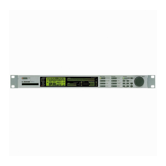
Page 8: Front Panel
FRONT PANEL DEFINED OVERLOAD User defined overload LED. ELECTRONIC POWER SWITCH CLIP LED OUTPUT PPM »Easy touch« Indicates that Output High resolution meters. Keep pressed for more than is clipped. 2 seconds to turn device off. PC CARD SLOT INDICATORS INPUT PPM EXPANDER GAIN REDUCTION... - Page 9 FRONT PANEL ADJUST wheel Sets parameter values and preset numbers. FUNCTIONS SECTION PROGRAM SECTION CONTROL SECTION MAIN PAGE RECALL This key allows you to edit Recall presets. Confirm operations the entire signal flow, from and switch individual blocks on/off. Input to Output. STORE Store and name presets.
-
Page 10: Rear Panel
REAR PANEL WARNING BALANCED INPUTS BALANCED OUTPUTS SYNC DIGITAL AUDIO RS485 CAUTION TO REDUCE THE RISK OF FIRE OR ELECTRIC SHOCK DO NOT EXPOSE THIS EQUIPMENT TO RAIN OR MOISTURE RISK OF ELECTRIC SHOCK DO NOT OPEN AVIS: RISQUE DE CHOC ELECTRIQUE-NE PAS OUVRIR. -
Page 11: Signal Flow Diagram
SIGNAL FLOW DBMAX INPUT PPM OUTPUT PPM Defined Overload Left Left In Level Right Right Trim Input Input Trim Output Selector Fader Out Fine L/R Left Ins 1 Ins 2 Ins 3 COMP Ins 4 ANALOG ANALOG INPUTS OUTPUTS [balanced] [balanced] Right Digital Out Gain... -
Page 12: Dbmax Setup
DBMAX SETUP The DBMAX is carefully designed to optimize or limit the overall level and enhance the energy in your material. The use of the five band Compressor, Limiter and Expander makes the dynamics section of the DBMAX very flexible, while maintaining the fidelity of the original material. - Page 13 DBMAX SETUP TV Production & Transmission applications Surround Production Suite The two applications for the DBMAX in this configuration are: 1. The DBMAX can be inserted pre master, to optimize the production. Note: Adjusting the L/R balance can cause serious changes to the surround encoded signal. 2.
-
Page 14: Basic Operation
REFERENCE LEVELS The Reference level settings are the heart of the DBMAX. If these parameters are not set properly, the DBMAX may not perform correctly. So please take the time to go through these level settings and make sure they are set correctly. The DBMAX is prepared to match several different predefined Reference Level setups. -
Page 15: Analog Levels
REFERENCE LEVELS Ref. Level Integration With Reference level you can set the reference point of the To simulate different types of meters, the defined overload can Compressor to eg. +4dBu. All Thresholds, except the Limiter work in proportion to an integration time. Digital meters have an Thresholds, are relative to this parameter. -
Page 16: Reference Levels Illustration
REFERENCE LEVELS OPERATING LEVELS: ____________________________ Ref. Level 0dBu (dBFS) -18dB Abs. Peak max +9dBu (dBFS) -9dB ____________________________ ANALOG LEVELS : In level 0dBFS +18dBu Trim Input Trim Output Out Fine L 0.0dB Out Fine R 0.0dB Analog In Analog Out Digital In Digital Out DIGITAL LEVELS:... -
Page 17: Recall
RECALL Bank indication Select which blocks to load from the new preset Select Preset Category Preset name Preset number Read only/On air indication Press the RECALL key to enter the Recall page. Factory/User Presets To recall/activate a preset: Factory Your own Your own - Use the ADJUST wheel to scroll through the presets. -
Page 18: Store - Delete And Preset Names
STORE - DELETE & PRESET NAMES Store Storing a preset with the same name - Press the STORE key. - Place the cursor next to the “Name” line (see illustration). - Select a location for your new preset using the ADJUST wheel (You can store your preset in the RAM bank or the Card bank). - Press OK and the preset is stored with the same name at the selected location. - Page 19 STORE What is stored where ? Global Parameters Global parameters describe your general working environment: Inputs used, System delay, Settings for Transmission or Production etc. Global parameters are not affected by setup or preset recalls. The parameters include: - Input and Output Blocks on the Main Page: Delay, Formats, HP and LP Filters, Rate Conversion, Dither and Output Fader.
-
Page 20: Main Page
MAIN PAGE Input INPUT EXPANDER COMPRESSOR LIMITER OUTPUT Black box indicates Input page 1 selected block Master Input Delay Page select in frames pr. second Input type Delay on/off selector switch Sample Rate Clock Master Input delay converter on/off select in milliseconds Input page 2 Process both channels (normal) - Page 21 MAIN PAGE Input Basic operation Clock - Output Sample Rate - Select the In section on the Main page by pressing the Select Master Clock: BLOCK keys. 44.1kHz/48kHz/DI/Sync - Press the PARAMETER keys to move the cursor. (44.1 and 48kHz are internally generated). - Use the ADJUST wheel to change values.
- Page 22 MAIN PAGE Input Look-ahead delay is automatically compensated by the Reference Level Compressor Attack settings in order prevent “holes” in the sound It is possible to keep the Reference Levels settings as default being generated. settings or let these settings follow the presets: “NO CHG”...
-
Page 23: Inserts
MAIN PAGE Inserts 1-3 On the following pages the different Insert options are explained. Please use this illustration for overview of the level handling in accordance to various parameters in the DBMAX . -
Page 24: Agc
MAIN PAGE Inserts 1-3 INPUT EXPANDER COMPRESSOR LIMITER OUTPUT Automatic Gain Min/Max Gain Control. Maximum/minimum gain limit you allow the AGC to perform on your signal. Low Level Target Low level limit for the AGC. Target Ratio Hold Release: Target level for AGC Release rate in dB/sec. - Page 25 MAIN PAGE Inserts 1-3 Inserts Target This is the Target value in dB related to the Ref. Levels setting. Select Insert 1, 2 or 3 by pressing the BLOCK keys Example: - The Ref. level is set to e.g. -12dBFS, Basic operation - The Target level is set to 2 - Use the MENU keys to highlight the field just below the...
-
Page 26: Dynamic Equalizer
MAIN PAGE Inserts 1-3 INPUT EXPANDER COMPRESSOR LIMITER OUTPUT Black box indicates selected block Dynamic Equalizer CURVE Sets the frequency characteristics of the dynamic damping filter. Gain reduction Indicates the actual gain reduction performed by the Frequency Dynamic EQ. Sets the working frequency of the Dyn-EQ. -
Page 27: Stereo Enhance
MAIN PAGE Inserts 1-3 Dyn EQ Added Width Graphical illustration of the actual added width. Threshold The actual possible added width depends on the stereo content of When the Input level exceeds the Threshold, the Dynamic the signal. If the source material is 100% mono no stereo Equalizer will be activated. -
Page 28: Normalizer
MAIN PAGE Inserts 1-3 INPUT EXPANDER COMPRESSOR LIMITER OUTPUT Normalizer Consecutive samples clipped. Counts the number of clipped samples within a 1 sec. time period. Normalizer Gain On/off switch Active Will blink when active. MS Decoding MS-Decode on/off switch. Mid-Side balance control MS Encoding Fine balance adjust... - Page 29 MAIN PAGE Inserts 1-3 Normalizer MS Decoding/Encoding MS (Mid/Side) miking technique uses a forward-facing Optimization of the level of your material begins in the directional mic and a side-facing bi-directional mic. Normalizer. The objective here is to increase the gain to a level MS recording offers very good stereo imaging with the added just below clipping.
-
Page 30: Expander
MAIN PAGE Expander INPUT EXPANDER COMPRESSOR LIMITER OUTPUT PAGE 1 Expander page select Gain Reduction Shows the actual gain reduction on each of Selected band indication the 5 individual bands. A dot indicates selected band or bands. By default all bands are selected, but Threshold Range you can adjust each band... - Page 31 MAIN PAGE Expander Expander Page 2 Expander Bypass Press Menu keys to select page 2 Press the gray BLOCK on/off key to bypass the Expander block. Attack Attack is the time the Expander uses to bring the reduced signal Select EXP by pressing the BLOCK keys to 1:1 when the signal exceeds the Threshold.
-
Page 32: Compressor
MAIN PAGE Compressor INPUT EXPANDER COMPRESSOR LIMITER OUTPUT Flag indication PAGE 1 Gain Reduction Page select Shows the actual gain reduction on each of the 5 individual bands. The Edit guide Arrow direction indicates whether the parameter value Less/More has been increased or Adjusts the intensity decreased since last Recall. - Page 33 MAIN PAGE Compressor The Compressor D - Delay time. (1-400ms) A “D” indicates that a Delay time has been added in the In block page 1 for the digital Inputs/ Select COM by pressing the BLOCK keys Outputs. The first 10ms. works as a look ahead-delay to increase the precision of processing.
- Page 34 MAIN PAGE Compressor INPUT EXPANDER COMPRESSOR LIMITER OUTPUT PAGE 3 Crest This parameter determines whether the Compressor should react to peaks, RMS (average) or something in between. Attack Hold Release Individual Attack From 10-200ms. Individual Release times for times for each of each of the five bands.
- Page 35 MAIN PAGE Compressor Page 3 Page 4 - Cross-over Menu Press MENU keys to enter the Cross-over Press MENU keys to enter page 3. frequency page (Xovr) Attack Cross-over point 1-4 The Attack time is the time the Compressor uses to reach the Cross-over frequencies may be altered on the last page of the gain reduction speciefied by the Ratio parameter set in page 2.
-
Page 36: Limiter
MAIN PAGE Limiter INPUT EXPANDER COMPRESSOR LIMITER OUTPUT PAGE 1 The Edit guide Arrow direction indicates whether the parameter value has been increased or decreased since last Recall. Limiter Threshold Limit on/off A dot indicates no changes. Separate Threshold Bypass Limiter on adjustment on each of individual bands. -
Page 37: The Limiter
MAIN PAGE Limiter The Limiter Page 3 - Cross-over Menu Select LIM by pressing the BLOCK keys Press MENU keys to enter the Cross-over frequency page (Xovr) Basic operation - Press the PARAMETER keys to select parameter. Cross-over point 1-4 - Turn the ADJUST wheel to change values. -
Page 38: Transmission Limiter
MAIN PAGE Post Dynamic Inserts INPUT EXPANDER COMPRESSOR LIMITER OUTPUT Transmission Limiter Insert especially for Transmission or Transmission emulation. Softclipper Emphasis First letter - Analog Second letter - Digital Lin/Linear - when type is set to off. Emphasis type Dynamic Limiter Release time pr. - Page 39 MAIN PAGE Post Dynamic Inserts Post Dynamics Inserts HF-compensation HF compensation is given by the Dynamic HF Limiter, ensuring Two different types of Limiters are available as post Dynamic optimum and distortion-free transmission. Inserts in the I4 block. The dynamic Transmission Limiter and the static Production Limiter.
-
Page 40: Output
MAIN PAGE Output INPUT EXPANDER COMPRESSOR LIMITER OUTPUT FADE SECTION CURVE sets the fade-out curve TIME sets the fade-out time FADE up/down/stop LEVEL set fader level manually. Note: Select no. of bits dithered to: If an external fader is connected, all of the above 8 bit parameters are disabled. - Page 41 Note: The Dither Resolution parameter is always reset when changing the primary Output. Dither Type In the DBMAX, TC Electronic has chosen to use TPDF Dither. This is the most user friendly type of Dither, and it does not restrict you from further downstream processing.
-
Page 42: Tools Flow
TOOLS Flow Flow In the Flow meter, you have five small peak meters, representing the level in the different sections of the DBMAX. The Flow meter refers to absolute peak in the Ref. Levels menu. When a block is overloading, use the parameter keys to select the current block and press OK for direct access. -
Page 43: Peak-Hold Meter
TOOLS Peak-Hold Meter Peak The Peak-Hold meter is an Output meter with infinite hold. It is possible to see the level of the maximum peak with 0.1dB precision. Press OK to reset the meter. Numeric readout of peak values TOOLS Phase Meter (correlation) Phase Meter The Phase meter displays the phase relationship... -
Page 44: Digital I/O
TOOLS Digital I/O - DIO RECEIVED STATUS BITS Pre-emphasis indicator: On/off Source device: DAT, CD, mixer etc Number of audio bits received Copyright: None, One copy only, Infinite copies Status bit info Copy status TOOLS Calibration Tone Calibration tone In Calibration you can choose between various test tones at definable level. -
Page 45: Calibration Tone
TOOLS DIO & Calibration Tone S/PDIF When S/PDIF is selected, the DBMAX will transmit its own This display has various indicators describing the consumer status bits out, meaning that any incoming ID will be received digital signal. lost. The DBMAX’s S/PDIF Output carries up to 24 bits. Only the S/PDIF signal contains copy protection information. -
Page 46: Utility
UTILITY Basic operation - Use the MENU keys to select parameter. - Use the ADJUST wheel to change values. _____________________________________________________ Display Viewing Angle Adjust for best contrast on the LCD display. Timing Calculations Based on fps. The delay in the In page 1. of the In block is displayed in both frames pr second and milliseconds. -
Page 47: Memory Backup
For information on how to achieve this modification please key for about 3 seconds, and all keys will be locked contact your local TC distributor or authorized TC Electronic including the ADJUST wheel. The display will say locked in the Service center. -
Page 48: Reset Page
RESET PAGE Store and load your own default settings Enter User data page Reset system parameters Clear all user presets Test Programs Type your name here and your phone number DONE Confirms/enters the printed data Basic operation • In “normal operation mode”, not the Reset page, setup all your - Enter the Reset page by holding the BYPASS key while preferred settings (Preset, Ref. -
Page 49: The Wizard
RESET PAGE WIZARD Reset System Parameters This will reset all system parameters back to the factory default. This reset will NOT delete the user presets of the DBMAX. Clear all Presets This will clear all Ram presets. Run Test Program Activates the built in Test Program. -
Page 50: Appendix
APPENDIX - Troubleshooting You press the POWER switch but there is no light - The POWER switch on the rear panel is switched off. The Input PPM meters don’t peak out - You are using analog Inputs, but the Input selector in the I/O menu is set to digital in. - The analog Input level is set too low. -
Page 51: Self Test
APPENDIX - Self test Press the BYPASS key while powering up to access MIDI I/O test the self-test and select “ RUN TEST PROGRAM”. Select MIDI I/O test by pressing OK. Connect MIDI Out to MIDI In. Use the ADJUST wheel to scroll through the different self tests. Prg. -
Page 52: Technical Specifications
TECHNICAL SPECIFICATIONS Digital Inputs and Outputs Connectors: XLR (AES/EBU) EN 55103-1 and EN 55103-2 Complies with: RCA Phono (S/PDIF) FCC part 15, Class B Formats: AES/EBU (24 bit), CISPR 22, Class B S/PDIF (20 bit), EIAJ CP-340, IEC 958 Output Dither: HPF TPDF dither 8-22 bit Safety Word Clock Input:... -
Page 53: Tutorial
APPENDIX Tutorial The unit is shipped with a number of factory presets identified as Delay on Input page no. 1 is set between 3 and 10 ms and turned ROM on the Recall page. Presets are only meant as starting points. We urge you to tailor Remember to setup appropriate Dither on the Out page if you use the sound to the application or profile you want. - Page 54 Peak Max. -3dB. If you have specific requirements or information about your setup, feel free to contact TC Electronic at info@tcelectronic.com If you want to off-set the spectral balance (Eq) of low level sig- nals, use the Band Levels on page no. 2 of the Compressor block.
-
Page 55: Glossary
APPENDIX Glossary AES/EBU Dither Professional digital in/out standard, using balanced XLR cables. Going from one type of bit resolution to a lower, e.g. from 24 bit The AES/EBU format can output 24 bit 96kHz. to 16 bit, you actually loose 8 bits of information. The process of cutting off bits is called truncation and it introduces digital distortion of low level signals, due to the lack of complete signal S/PDIF... -
Page 56: Soldering Instructions
APPENDIX Soldering instructions MIDI Cable DIN CONNECTOR DIN CONNECTOR 5POLE - MALE 5POLE - MALE max. 10m 45 degrees 45 degrees SHIELDED CABLE (3 or 5 wires + screen) Note Note NOTE! On TC units with RS485 interface pins 1 and 3 on the DIN connectors are reserved for RS485 connection. Therefore, if you are connecting the unit to other equipment that use these pins, please make sure to use 3-wire standard MIDI type cable (not a five wire MIDI-PLUS type). - Page 57 APPENDIX Soldering instructions XLR - XLR Jack (unbalanced) - XLR Jack (balanced) - XLR Pin 1 - Pin 1 (Ground) Sleeve - Pin 1 (Ground) Sleeve - Pin 1 (Ground) Pin 2 - Pin 2 (Hot) Tip - Pin 2 (Hot) Tip - Pin 2 (Hot) RING Pin 3 - Pin 3 (Cold)
-
Page 58: Preset List
PRESET LIST Presets for Mastering and Production Name Main Function Typical Level Setup Applications EBU Limiter Limiter, Europe EBU Broadcast OB, PP NAB Limiter Brickwall Limiter, US NAB Broadcast OB, PP EBU Comp & Lim Optimize & Limit, Europe EBU Broadcast OB, PP NAB Comp &... - Page 59 PRESET LIST Presets for Digital and FM Radio Name Main Function Typical Level Setup Applications Optimize & Limit EBU Broadcast BC, DR DAB <AGC> Optimize & Limit EBU Broadcast BC, DR Classical DAB Optimize & Limit EBU Broadcast BC, DR FM Subtle Opti level, width &...
-
Page 60: Faq
Remote control FAQ This section covers som of the most frequently asked questions regarding remote control of the DBMAX. Q: What parameters can be set using serial remote control of the DBMax? A: Preset change and Bypass using an RS485/422/232 controller. -
Page 61: Optional Master Fader
MASTER FADER Why Make a Master Fader? If a fade is performed before the DBMAX, the Compressor will try to increase the level as the fade decreases. To avoid this problem, fades must always be done after the DBMAX. The Master Fader makes it possible to perform a manual fade on the very Output of the DBMAX, enabling you to keep your fade in digital domain and ensuring perfect tracking of Left and Right.
Need help?
Do you have a question about the DBMAX-V 2.90 and is the answer not in the manual?
Questions and answers