
Related Manuals for Supero Supero SC733 Series


Summary of Contents for Supero Supero SC733 Series
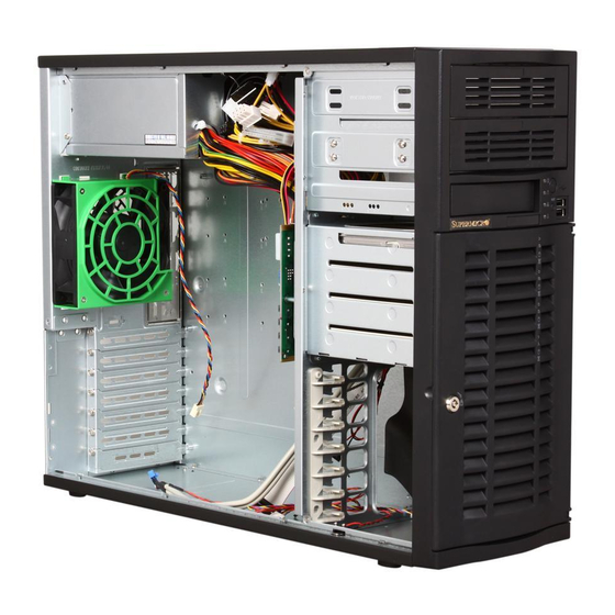
- Page 1 UPER ® SC733 CHASSIS SERIES Reset Reset SC733TQ-665B SC733TQ-645B SC733T-645(B) SC733i-645(B) SC733E-465B SC733TQ-465B SC733T-465B SC733i-465(B) SC733T-450(B) SC733i-450(B) SC733T-350(B) SC733i-300(B) USER’S MANUAL 1.0d...
- Page 2 Please Note: For the most up-to-date version of this manual, please see our web site at www.supermicro.com. Super Micro Computer, Inc. ("Supermicro") reserves the right to make changes to the product described in this manual at any time and without notice. This product, including software, if any, and documentation may not, in whole or in part, be copied, photocopied, reproduced, translated or reduced to any medium or machine without prior written consent.
- Page 3 SC733 chassis. Installation and maintenance should be performed by experienced technicians only. Supermicro’s SC733 chassis features a unique and highly-optimized design for dual- core Xeon platforms. The chassis is equipped with a 300W, 350W, 450W, 465W, 645W, or 665W high-efficiency power supply for superb power savings.
-
Page 4: Manual Organization
SC733 Chassis Manual Manual Organization Chapter 1: Introduction The first chapter provides a checklist of the main components included with this chassis and describes the main features of the SC733 chassis. This chapter also includes contact information. Chapter 2: System Safety This chapter lists warnings, precautions, and system safety. -
Page 5: Table Of Contents
Table of Contents Chapter 1 Introduction Overview ......................1-1 Shipping List ....................1-1 Where to get Replacement Components ............1-2 Contacting Supermicro ..................1-3 Returning Merchandise for Service..............1-4 Chapter 2 System Safety Overview ......................2-1 Warnings and Precautions ................2-1 Electrical Safety Precautions ................ - Page 6 SC733 Chassis Manual Notes...
-
Page 7: Chapter 1 Introduction
Chapter 1 Introduction Overview Supermicro’s SC733 chassis features a unique and highly-optimized design. The chassis is equipped with high-efficiency power supply. High-performance fans provide ample optimized cooling for FB-DIMM memory modules and four hot-swappable drive bays offer maximum storage capacity. -
Page 8: Where To Get Replacement Components
Supermicro Authorized Distributors / System Integrators / Resellers. A list of Supermicro Authorized Distributors / System Integrators /Reseller can be found at: http://www.supermicro.com. Click the Where... -
Page 9: Contacting Supermicro
Super Micro Computer, Inc. 980 Rock Ave. San Jose, CA 95131 U.S.A. Tel: +1 (408) 503-8000 Fax: +1 (408) 503-8008 Email: marketing@supermicro.com (General Information) support@supermicro.com (Technical Support) Web Site: www.supermicro.com Europe Address: Super Micro Computer B.V. Het Sterrenbeeld 28, 5215 ML... -
Page 10: Returning Merchandise For Service
For faster service, RMA authorizations may be requested online (http://www. supermicro.com/support/rma/). Whenever possible, repack the chassis in the original Supermicro carton, using the original packaging material. If these are no longer available, be sure to pack the chassis securely, using packaging material to surround the chassis so that it does not shift within the carton and become damaged during shipping. -
Page 11: Chapter 2 System Safety
Chapter 2: System Safety Chapter 2 System Safety Overview This chapter provides a quick setup checklist to get your chassis up and running. Following the steps in order given should enable you to have your chassis setup and operational within a minimal amount of time. This quick set up assumes that you are an experienced technician, famailiar with common concepts and terminology. -
Page 12: General Safety Precautions
SC733 Chassis Manual system and then unplug the power cords from all the power supply modules in the system. • When working around exposed electrical circuits, another person who is fa- miliar with the power-off controls should be nearby to switch off the power, if necessary. -
Page 13: System Safety
Chapter 2: System Safety • While working on the system, do not wear loose clothing such as neckties and unbuttoned shirt sleeves, which can come into contact with electrical circuits or be pulled into a cooling fan. • Remove any jewelry or metal objects from your body, which are excellent metal conductors that can create short circuits and harm you if they come into contact with printed circuit boards or areas where power is present. - Page 14 SC733 Chassis Manual • For grounding purposes, make sure your computer chassis provides excellent conductivity between the power supply, the case, the mounting fasteners and the serverboard.
-
Page 15: Chapter 3 System Interface
Chapter 3: System Interface Chapter 3 System Interface Overview There are several LEDs on the control panel as well as others on the drive carriers to keep you constantly informed of the overall status of the system as well as the activity and health of specific components. -
Page 16: Control Panel Buttons
SC733 Chassis Manual Control Panel Buttons There are two push-buttons located on the front of the chassis. These are (in order from left to right) a reset button and a power on/off button. • Reset: The reset button is used to reboot the system. •... - Page 17 Chapter 3: System Interface • HDD: Indicates IDE channel activity. SAS/SATA drive, SCSI drive, and/or DVD- ROM drive activity when flashing. • NIC1: Indicates network activity on GLAN1 when flashing. • Overheat: Indicates an overheating or fan failure condition when flashing. Correcting an Overheat/Fan Fail Condition Check the routing of the cables and move any cables the restrict airflow.
- Page 18 SC733 Chassis Manual Notes...
-
Page 19: Chapter 4 Chassis Setup And Maintenance
Chapter 4: Chassis Setup and Maintenance Chapter 4 Chassis Setup and Maintenance Overview This chapter covers the steps required to install components and perform mainte- nance on the chassis. The only tool you will need to install components and perform maintenance is a Phillips screwdriver. -
Page 20: Removing The Chassis Cover
SC733 Chassis Manual Removing the Chassis Cover Remove Screws Figure 4-1: Removing the Chassis Cover Removing the Chassis Cover: Disconnect the chassis from any power source. On the rear of the chassis, remove the two screws holding the cover in place. Slide the cover back, toward the rear of the chassis Lift the cover off the chassis. -
Page 21: Installing Hard Drives In The Sc733I Model Chassis
Chapter 4: Chassis Setup and Maintenance Installing Hard Drives in the SC733i Model Chassis Remove Screws Figure 4-2: Removing the Hard Drive Module The SC733i chassis must be powered-down before hard drives can be removed from the hard drive carriers. Replacing Hard Drives in the SC733i Chassis Disconnect the chassis from any power source. - Page 22 SC733 Chassis Manual Remove Screws Remove Screws Figure 4-3: Removing Drives from the SC733i Hard Drive Module Remove the 4 screws securing each of the hard drives. Slide the drive (or dummy drive) out of the hard drive module. Insert the replacement drive into the hard drive module. Slide the hard drive module back into the chassis.
-
Page 23: Installing Hard Drives In The Sc733T And Sc733Tq
Using the drive carrier handle, gently pull the drive carrier out of the chassis. Warning! Enterprise level hard disk drives are recommended for use in Supermicro chassis and servers. For information on rec- ommended HDDs, visit the Supermicro Web site at http://www. - Page 24 SC733 Chassis Manual Drive Carrier Dummy Drive Figure 4-5: Chassis Drive Carrier The drives are mounted in drive trays to simplify their installation and removal from the chassis. These trays also help promote proper airflow for the drive bays. Warning: Except for short periods of time (swapping hard drives), do not operate the server with the chassis drive bays empty.
- Page 25 Chapter 4: Chassis Setup and Maintenance SAS/SATA or SCSI Hard Drive Drive Carrier Figure 4-7: Removing Hard Drive Slide the hard drive into the carrier with the printed circuit board side facing down. Carefully align the mounting holes in both the drive carrier and the hard drive. Secure the hard drive to the carrier using six screws.
-
Page 26: Installing A Peripheral Drive
SC733 Chassis Manual Installing a Peripheral Drive SC733 chassis models have peripheral drive bays, in which an optional drive may be installed. This may be a CD-ROM, DVD-ROM or other device. In the unlikely event that it becomes necessary to replace a peripheral drive, use the following procedure. -
Page 27: Installing The Motherboard, I/O Shield And Standoffs
Chapter 4: Chassis Setup and Maintenance Installing the Motherboard, I/O Shield and Standoffs I/O Shield Figure 4-10: I/O Shield Placement I/O Shield An I/O shield holds the motherboard ports in place. Install the I/O shield before you install the motherboard. Motherboards are sold separately from the SC733 chassis and come with I/O shields specific to the motherboard. -
Page 28: Permanent And Optional Standoffs
SC733 Chassis Manual Permanent and Optional Standoffs Standoffs prevent short circuits by securing space between the motherboard and the chassis surface. The SC733 chassis includes permanent standoffs in locations used by most motherboards. These standoffs accept the rounded Phillips head screws included in the SC733 accessories packaging. -
Page 29: Motherboard Installation
Chapter 4: Chassis Setup and Maintenance Motherboard Installation Installing the Motherboard: Review the documentation that came with your motherboard. Become familiar with component placement, requirements, precautions, and cable connec- tions. Open the chassis cover. As required by your motherboard, install standoffs in any areas that do not have a permanent standoff. -
Page 30: Installing Add-On And Expansion Cards
SC733 Chassis Manual Installing Add-on and Expansion Cards Add-on/Expansion Card Slots Remove Screws Figure 4-12: Installing Add-on or Expansion Cards Add-on Card/Expansion Slot Setup SC733 chassis include slots for add-on cards and expansion cards. The number of cards you can use depends on your chassis model and motherboard model. Installing Add-on and Expansion Cards Disconnect the power supply, set the chassis on a flat surface, and open the chassis cover. -
Page 31: Removing The Fan Duct And System Fan
Chapter 4: Chassis Setup and Maintenance Removing the Fan Duct and System Fan Release Tabs Release Tabs Release Tabs Screw Figure 4-13: Replacing the Fan shroud The fan duct concentrates airflow to maximize fan efficiency. Removing the Fan Duct and System Fan Disconnect the chassis from any power source. -
Page 32: Checking The Server's Air Flow
SC733 Chassis Manual Checking the Server's Air Flow Checking the Server's Air flow Make sure there are no objects to obstruct airflow in and out of the server. In addition, if you are using a front bezel, make sure the bezel's filter is replaced periodically. -
Page 33: 4-10 Power Supply
An il- luminated green light indicates that the power supply is operating. New units can be ordered directly from Supermicro (see the contact information in the Preface). - Page 34 SC733 Chassis Manual Power Supply Figure 4-14: Removing the Power Supply Changing the Power Supply Disconnect the chassis from any power source. Remove the screws securing the power supply to the chassis, which are located on the rear of the chassis. Pull the power supply out of the chassis.
-
Page 35: Appendix A Cables, Screws, And Other Accessories
This appendix lists supported cables for your chassis system. It only includes the most commonly used components and configurations. For more compatible cables, refer to the manufacturer of the motherboard you are using and our Web site at: www.supermicro.com. A-2 Cables Included with SC733 Chassis SC733TQ-645(B), SC733i-645(B), SC733TQ-665(B) - Page 36 SC733 Chassis Manual A-3 Compatible Cables These cables are compatible with the SC733 Chassis. Alternate SAS/SATA Cables Some compatible motherboards have different connectors. If your motherboard has only one SAS connector that the SAS/SATA cables must share, use one of the following cables.
-
Page 37: Extending Power Cables
Appendix A: Chassis Cables Extending Power Cables Although Supermicro chassis are designed with to be efficient and cost-effective, some compatible motherboards have power connectors located in different areas. To use these motherboards you may have to extend the power cables to the mother boards. - Page 38 SC733 Chassis Manual A-4 Chassis Screws The accessory box includes all the screws needed to set up your chassis. This section lists and describes the most common screws used. Your chassis may not require all the parts listed. HARD DRIVE Flat head Pan head 6-32 x 5 mm...
-
Page 39: Appendix B Sc733 Power Supply Specifications
Appendix B: Power Supply Specifications Appendix B SC733 Power Supply Specifications This appendix lists power supply specifications for your chassis system. SC733 665W 645W 465W 450W 350W 300W PWS-665 PWS- PWS-465 PWS- PWS- PWS- Part # 0060 450(B) 0059 0041 100 - 100 - 100 -... - Page 40 SC733 Chassis Manual Notes...
-
Page 41: Appendix C Sas-733Tq Backplane Specifications
SAS-733TQ Backplane Specifications Appendix C SAS-733TQ Backplane Specifications Safety Information and Technical Specifications C-1 Safety Guidelines To avoid personal injury and property damage, please carefully follow all the safety steps listed below when accessing your system or handling the components: ESD Safety Guidelines Electrostatic Discharge (ESD) can damage electronic com ponents. - Page 42 This manual reflects SAS-733TQ Revision 3.00, the most current release available at the time of publication. Always refer to the Supermicro Web site at www.supermi- cro.com for the latest updates, compatible parts and supported configurations.
- Page 43 SAS-733TQ Backplane Specifications Supporting SES-2 (SCSI Enclosure Services-2) protocol, providing the following features: • Drive activity and drive failure indication for each drive slot • Overheat/drive failure alarm via a buzzer* installed on the backplane • An overheat/drive failure LED Indicator built in •...
-
Page 44: Front Connectors
SC733 Chassis Manual C-4 Jumper Settings and Pin Definitions COM PONENT SI DE LAYER 1 Front Jumper/Connector Locations TOP SI LK SCREEN JP13 JP10 OH/DRI VE FAI L JP33: CTRL_I D R221 FAN FAI L R269 1- 2: SGPI O R210 2- 3: I 2C R149... - Page 45 SAS-733TQ Backplane Specifications C-5 Front Connector Pin Definitions Backplane Main Power Connectors (JP10, JP13) Pin Definitions Backplane Main Power 4-Pin Connector (JP10) You must use the 4-pin power con- Pin # Definition nectors: JP10 and JP13 to provide adequate power to the backplane. 1 +12V See the table on the right for pin 2 and 3 Gound...
- Page 46 SC733 Chassis Manual Front Overheat/Drive Failure LED Indicators - D3/D4 Front LED State Specification Overheat, drive failure or fan failure Fan failure only Front Panel Jumper Settings and Pin Definitions Jumper Description Definition JP18 Open (Default) Normal Closed Buzzer reset JP26 Open (Default) Act #0 - 3 In...
- Page 47 SAS-733TQ Backplane Specifications C-6 Rear Connectors and LED Indicators Rear connector and LED locations SAS#3 SAS#2 SAS#1 SAS#0 Figure C-2 - Rear View Rear Connectors Rear Connector Specification J1 (Rear) SAS#0 HDD (Connected to HDD) J2 (Rear) SAS#1 HDD (Connected to HDD) J3 (Rear) SAS#2 HDD (Connected to HDD) J4 (Rear)
-
Page 48: Rear Connectors And Led Indicators
SC733 Chassis Manual Rear Connectors and LED Indicators Rear LED Indicators Specification D12 (Rear) SAS#0 Activity LED D13 (Rear) SAS#1 Activity LED D14 (Rear) SAS#2 Activity LED D15 (Rear) SAS#3 Activity LED D5 (Rear) SAS#0 Fail LED D6 (Rear) SAS#1 Fail LED D7 (Rear) SAS#2 Fail LED D8 (Rear) -
Page 49: Appendix D Sata-733 Backplane Specifications
This manual reflects SATA-733 Revision 3.00, the most current release available at the time of publication. Always refer to the Supermicro Web site at www.supermicro. com for the latest updates, compatible parts and supported configurations. - Page 50 SC733 Chassis Manual Figure D-1: SATA-733 Backplane Jumper Description Setting JP18 Buzzer Reset* Alarm Reset Header JP25 Overheat Temperature Open: 45ºC Pins 1-2: 50º C (Default) Pins 2-3: 55º C JP26 SATA Drive Activity Drive Activity JP28 Fan Sense Pins 1-2: Enable Pins 2-3: Diable (Default) *The buzzer sound indicates that a condition requiring immediate attention has occurred.
- Page 51 Appendix D: SATA-733 Backplane Specifications Notes...
- Page 52 SC733 Chassis Manual Disclaimer (cont.) The products sold by Supermicro are not intended for and will not be used in life sup- port systems, medical equipment, nuclear facilities or systems, aircraft, aircraft devices, aircraft/emergency communication devices or other critical systems whose failure to per- form be reasonably expected to result in significant injury or loss of life or catastrophic property damage.
Need help?
Do you have a question about the Supero SC733 Series and is the answer not in the manual?
Questions and answers