
Related Manuals for Supero SC743 Series


Summary of Contents for Supero SC743 Series
- Page 1 UPER ® SC743 Chassis Series SC743TQ-865B-SQ SC743TQ-865(B) SC743TQ-R760(B) SC743S2-R760(B) SC743S1-R760(B) SC743T-R760(B) SC743i-R760(B) SC743i-665B SC743T-665B SC743i-500B SC743T-500B SC743i-465B USER’S MANUAL 1.2d...
- Page 2 This product, including software and documentation, is the property of Supermicro and/or its licensors, and is supplied only under a license. Any use or reproduction of this product is not allowed, except as expressly permitted by the terms of said license.
- Page 3 SC743 chassis. Installation and maintenance should be performed by experienced technicians only. Supermicro’s SC743 chassis features a unique and highly-optimized design. The chassis is equipped with a 465, 500, 665, 760 or 865 Watt power supply, and high- performance fans provide ample optimized cooling.
-
Page 4: Manual Organization
SC743 Chassis Manual Manual Organization Chapter 1: Introduction The first chapter provides a checklist of the main components included with this chassis and describes the main features of the SC743 chassis. This chapter also includes contact information. Chapter 2: System Safety This chapter lists warnings, precautions, and system safety. -
Page 5: Table Of Contents
Chapter 1 Introduction Overview ......................1-1 Shipping List ....................1-1 Part Numbers ....................1-1 Where to get Replacement Components ............1-2 Contacting Supermicro ..................1-3 Returning Merchandise for Service..............1-4 Chapter 2 System Safety Overview ......................2-1 Warnings and Precautions ................2-1 Preparing for Setup .................. - Page 6 SC743 Chassis Manual Standard Cooling Systems ................4-9 Removing the Air Shroud ................4-11 Installing the Motherboard ................4-12 4-10 Installing Expansion Cards ................4-14 4-11 Power Supply ....................4-16 465, 500, 665 and 865 Watt Power Supplies ..........4-16 760 Watt Power Supply ................4-18 4-12 Accessing the Interior Space Between the Backplane and the Midplane ..
-
Page 7: Chapter 1 Introduction
Supermicro’s SC743 chassis features a unique and highly-optimized design. The chassis is equipped with a high-efficiency 80%+ low-noise power supply. Shipping List Part Numbers Please visit the the Supermicro Web site for the latest shiping lists and part numbers for your particular chassis model at http://www.supermicro.com/ Power Model... -
Page 8: Where To Get Replacement Components
Supermicro Authorized Distributors/ System Integrators/Resellers. A list of Supermicro Authorized Distributors/System Integrators/Reseller can be found at: http://www.supermicro.com. Click the Where to Buy link. -
Page 9: Contacting Supermicro
Super Micro Computer, Inc. 980 Rock Ave. San Jose, CA 95131 U.S.A. Tel: +1 (408) 503-8000 Fax: +1 (408) 503-8008 Email: marketing@supermicro.com (General Information) support@supermicro.com (Technical Support) Web Site: www.supermicro.com Europe Address: Super Micro Computer B.V. Het Sterrenbeeld 28, 5215 ML... -
Page 10: Returning Merchandise For Service
For faster service, RMA authorizations may be requested online (http://www. supermicro.com/support/rma/). Whenever possible, repack the chassis in the original Supermicro carton, using the original packaging material. If these are no longer available, be sure to pack the chassis securely, using packaging material to surround the chassis so that it does not shift within the carton and become damaged during shipping. -
Page 11: Chapter 2 System Safety
Chapter 2: System Safety Chapter 2 System Safety Overview This chapter provides a quick setup checklist to get your chassis up and running. Following the steps in the order given should enable you to have your chassis set up and operational within a minimal amount of time. This quick setup assumes that you are an experienced technician, familiar with common concepts and terminology. -
Page 12: Electrical Safety Precautions
SC743 Chassis Manual Electrical Safety Precautions Basic electrical safety precautions should be followed to protect yourself from harm and the SC743 from damage: • Be aware of the locations of the power on/off switch on the chassis as well as the room’s emergency power-off switch, disconnection switch or electrical outlet. -
Page 13: General Safety Precautions
Chapter 2: System Safety • Please handle used batteries carefully. Do not damage the battery in any way; a damaged battery may release hazardous materials into the environment. Do not discard a used battery in the garbage or a public landfill. Please comply with the regulations set up by your local hazardous waste management agency to dispose of your used battery properly. - Page 14 SC743 Chassis Manual • Use a grounded wrist strap designed to prevent static discharge. • Keep all components and printed circuit boards (PCBs) in their antistatic bags until ready for use. • Touch a grounded metal object before removing any board from its antistatic bag.
-
Page 15: Chapter 3 Chassis Components
• Up to seven expansion cards For the latest shipping lists, visit our Web site at: http://www.supermicro.com. Mounting to a Rack (Optional) The SC743 can be placed in a rack for secure storage and use. To set up your rack follow the step-by-step instructions included in this manual. -
Page 16: Where To Get Replacement Components
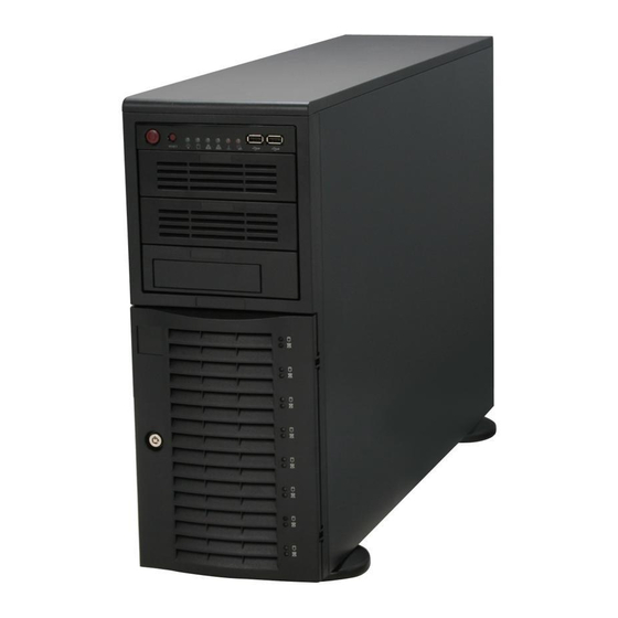
Supermicro Authorized Distributors/ System Integrators/Resellers. A list of Supermicro Authorized Distributors/System Integrators/Resellers can be found at: http://www.supermicro.com. Click the Where to Buy link Front Control Panel The following diagram defines each component of the front LED panel. -
Page 17: Control Panel Buttons
Chapter 3: Chassis Components Control Panel Buttons There are two push-buttons located on the front of the chassis. These are (in order from left to right) a power on/off button and a reset button. • Power: The main power switch is used to apply or remove power from the power supply to the server system. - Page 18 SC743 Chassis Manual • HDD: Indicates IDE channel activity. SAS/SATA drive, SCSI drive, and/or DVD- ROM drive activity when flashing. • NIC1: Indicates network activity on GLAN1 when flashing. • NIC2: Indicates network activity on GLAN2 when flashing. • Overheat/Fan Fail: When this LED flashes it indicates a fan failure.
- Page 19 Chapter 3: Chassis Components • Power Fail: Indicates a power failure to the system's power supply units.
- Page 20 SC743 Chassis Manual Notes...
-
Page 21: Chapter 4 Chassis Setup And Maintenance
Chapter 4: Chassis Setup and Maintenance Chapter 4 Chassis Setup and Maintenance Overview This chapter covers the steps required to install components and perform mainte- nance on the chassis. The only tool you will need to install components and perform maintenance is a Phillips screwdriver. -
Page 22: Removing The Chassis Side And Top Covers
SC743 Chassis Manual Removing the Chassis Side and Top Covers Disconnecting the Chassis from the Power Source Turn off all peripheral devices and turn off the power supply to the SC743. Disconnect the AC power cords from the system. Disconnect all cables and label the cables for easy identification. Warning: Use a grounded wrist strap designed to prevent static discharge when handling compo- nents. -
Page 23: Removing The Top Cover
Chapter 4: Chassis Setup and Maintenance When mounting the SC743 into a rack or changing the power supply, it is necessary to remove the top cover from the chassis. Removing the Top Cover Removing the Top Cover of the Chassis Disconnect the chassis from any power source. - Page 24 SC743 Chassis Manual Accessing the Hot-Swappable Drive Carriers Hot-swappable drives may be removed and installed in the chassis without power- ing-down the system and without opening the chassis cover. Accessing and Removing Hard Drive Carriers Unlock and open the drive carrier door as shown. Press the release tab located on the drive carrier.
- Page 25 Installing the Hard Drive Removing the Dummy Drive Figure 4-5: Hard Drive Carrier Warning! Enterprise level hard disk drives are recommended for use in Supermicro chassis and servers. For information on rec- ommended HDDs, visit the Supermicro Web site at http://www. supermicro.com/products/nfo/files/storage/SAS-1-CompList- 110909.pdf...
-
Page 26: Installing Fixed Hard Drives In Sc743I Series Chassis Models
SC743 Chassis Manual Installing Fixed Hard Drives in SC743i Series Chassis Models The SC743i series chassis features dual fixed storage modules. The system must be powered-down and disconnected from any power source before installing or removing hard drives. Disconnecting the Chassis from the Power Source Turn off all peripheral devices and turn off the power supply to the SC743. -
Page 27: Configuring The Storage Module
Chapter 4: Chassis Setup and Maintenance Configuring the Storage Module Storage Module Options The storage module can be configured to accommodate a variety of data storage devices such as CD, IDE, DVD and floppy drives. The chassis may be rotated from a vertical tower position, to a horizontal rack mounting position to accommodate use of these devices. - Page 28 SC743 Chassis Manual Configuring the Storage Module for 5.25" Devices Remove the 5.25” drive carriers from the storage module. Remove the screws and drive carrier brackets from the drive carriers. Install the 5.25” devices into the storage module. Replace the module back into the chassis. Ensure that the storage module is securely locked into position.
-
Page 29: Removing And Replacing The System Fans
Chapter 4: Chassis Setup and Maintenance Removing and Replacing the System Fans Before installing the motherboard in the chassis or accessing the motherboard after installation, it is necessary to remove the system fans. One set is located at the rear of the chassis, the other set is located in the middle of the chassis. - Page 30 SC743 Chassis Manual Removing Rear Chassis Fans Locate the release tab on the top of the chassis fan, at the rear of the chas- sis. Push the release tab down to unlock the fan. Once the fan is unlocked, tip it forward and out of the chassis. When replacing the rear chassis fan, push the fan back into the fan module until a click is heard, indicating that the fan has locked into position.
-
Page 31: Removing The Air Shroud
Chapter 4: Chassis Setup and Maintenance Removing the Air Shroud Before installing the motherboard in the chassis or accessing the motherboard after installation, it is necessary to remove the air shroud between the two sets of system fans. SC743TQ-865B-SQ model chassis are equipped with a specialized air shroud to accommodate the super quiet front and rear fans. -
Page 32: Installing The Motherboard
SC743 Chassis Manual Installing the Motherboard Prior to Installing the Motherboard Before the motherboard can be installed or removed, the air shroud must be re- moved, as directed in sections 4-8. The following information is for reference only, the motherboard is not included with the SC743 chassis. Identify the locations of the following components: •... - Page 33 Chapter 4: Chassis Setup and Maintenance Secure the heatsink to the motherboard as directed by the motherboard documentation. Secure the motherboard to the chassis using Type A screws, which are in- cluded in the chassis accessory kit. Do not exceed eight pounds of torque per square inch when tightening down the motherboard.
-
Page 34: Installing Expansion Cards
SC743 Chassis Manual 4-10 Installing Expansion Cards After installing the motherboard, expansion cards may be installed into the chas- sis. Installing Expansion Cards Locate the release tab on the top of the PCI slot bracket Gently apply pressure on the middle of the release tab to unlock the bracket as shown. - Page 35 Chapter 4: Chassis Setup and Maintenance Once the bracket is unlocked, pull the release tab upward and remove the bracket from the chassis. Gently slide the expansion card bracket into the PCI slot until it clicks into place. 4-15...
-
Page 36: Power Supply
SC743 Chassis Manual 4-11 Power Supply The SC743 chassis includes a power supply rated at either 465, 500, 665, 760 or 865 Watts. In the unlikely event that you need to replace the power supply, simply follow the directions for your specific power supply below. Warning: Always unplug the power cord before re- moving the power supply. - Page 37 Chapter 4: Chassis Setup and Maintenance Remove Screws Figure 4-15: Removing the Interior Chassis Screws on the Power Supply Using a Phillips head screwdriver, remove the five screws securing the power supply to the chassis as shown above, and set them aside for later use. Carefully lift the power supply up and out of the chassis.
-
Page 38: Watt Power Supply
SC743 Chassis Manual 760 Watt Power Supply The 760 Watt power supply is a triple redundant power supply with a different con- figuration than that of the 465, 500, 665 and 865 Watt power supplies. Installing the Power Supply Unplug the AC power cord from the power supply. Push the release tab on the left side of each power supply to release it from the locked position. -
Page 39: Accessing The Interior Space Between The Backplane And The Midplane
Chapter 4: Chassis Setup and Maintenance 4-12 Accessing the Interior Space Between the Backplane and the Midplane For easy access to the interior space between the backplane and the midplane, follow the instructions below before installing components or cables into this area. Accessing the Interior Space Remove the two screws as shown below and set them aside for future use. -
Page 40: Scsi (Super) Gem Driver Installation Instructions For Windows Os
Note: This driver is not necessary for other operating systems. If you have two SCA backplanes, you will need to install the driver twice. The driver is located on the Super Micro motherboard driver CD or may be downloaded from the Supermicro ftp site: ftp://ftp.supermicro.com/driver/Qlogic/ Follow the procedure below to install this driver onto your system. - Page 41 Chapter 4: Chassis Setup and Maintenance Installing the Driver (Alternative Procedure) Right click the “My Computer” icon on your desktop and choose Properties. Click on the Hardware tab and select Device Manager to bring up the list of system devices. You may see one or two yellow question marks (?) that read QLogic GEM354 or GEM318 SCSI Processor Device.
- Page 42 SC743 Chassis Manual Notes 4-22...
-
Page 43: Chapter 5 Rack Installation
Chapter 5: Rack Installation Chapter 5 Rack Installation Overview This chapter provides instructions on installing the chassis into a rack. Following these steps in the order given should enable you to have the system installed in a minimal amount of time. Unpacking the System You should inspect the box the chassis was shipped in, and note if it was damaged in any way. -
Page 44: Rack Precautions
SC743 Chassis Manual • This product is only to be installed in a Restricted Access Location (dedicated equipment rooms, service closets and similar environments). Warnings and Precautions! Rack Precautions • Ensure that the leveling jacks on the bottom of the rack are fully extended to the floor with the full weight of the rack resting on them. -
Page 45: Rack Mounting Considerations
Chapter 5: Rack Installation Rack Mounting Considerations Ambient Operating Temperature If installed in a closed or multi-unit rack assembly, the ambient operating tempera- ture of the rack environment may be greater than the ambient temperature of the room. Therefore, consideration should be given to installing the equipment in an environment compatible with the manufacturer’s maximum rated ambient tempera- ture (TMRA). -
Page 46: Installing The Chassis Rack Mounting Rails
SC743 Chassis Manual Installing the Chassis Rack Mounting Rails Before Installing the Chassis Rails Unplug the power cord from the from the power supply. Secure the chassis cover. Remove all external devices and connectors. Installing the Inner Chassis Rails Locate the pair of inner rails and two sets of screws (6 screws per set) that are included in the shipping package. - Page 47 Chapter 5: Rack Installation Installing the Outer Chassis Rails Locate the two pairs of outer rails. Each pair consists of one middle rail, one end bracket and one end rail as shown. Middle Rail End Rail End Bracket Figure 5-2: Assembling the Outer Chassis Rails Insert the end bracket and the end rail onto the middle rail and secure them with the screws as shown.
- Page 48 SC743 Chassis Manual Outer Rail Assemblies Inner Rails Figure 5-3: Mounting the Chassis into a Rack...
-
Page 49: Appendix A Cables, Screws, And Other Accessories
This appendix lists supported cables for your chassis system. It only includes the most commonly used components and configurations. For more compatible cables, refer to the manufacturer of the motherboard you are using and to the Supermicro Web site at: www.supermicro.com. - Page 50 SC743 Chassis Manual SC743T Series (SAS/SATA) Part # Type Length Description CBL-0044L Cable SATA cable (Amphenol) Round 16-pin to 16-pin front panel CBL-0087 Cable 20" ribbon cable CBL-0084 Cable 6" Split converter cable 12V 8-pin to 8-pin power connector CBL-0062L Cable 7.9"...
-
Page 51: Extending Power Cables
Appendix A: Chassis Cables Extending Power Cables Although Supermicro chassis are designed with to be efficient and cost-effective, some compatible motherboards have power connectors located in different areas. To use these motherboards you may have to extend the power cables to the mother boards. -
Page 52: Chassis Screws
SC743 Chassis Manual A-3 Chassis Screws The accessory box includes all the screws needed to set up your chassis. This section lists and describes the most common screws used. Your chassis may not require all the parts listed. HARD DRIVE Flat head Pan head 6-32 x 5 mm... -
Page 53: Appendix B Power Supply Specifications
Appendix B: Power Supply Specifications Appendix B Power Supply Specifications B-1 Power Supply Options This appendix lists power supply specifications for your chassis system. 465W MFR Part # PWS-465-PQ 100 - 240V Rated AC Voltage 60 - 50Hz 6 - 3 Amp +5V standby 3 Amp +12V 35 Amp +5V 20 Amp... - Page 54 SC743 Chassis Manual 665W MFR Part # PWS-665-PQ 100 - 240V Rated AC Voltage 50 - 60Hz 10- 5 Amp +5V standby 6 Amp +12V 54.0 Amp +5V 30.0 Amp +3.3V 24 Amp -12V 0.5 Amp R760W MFR Part # PWS-0056 100 - 240V Rated AC Voltage...
-
Page 55: Appendix C Cse-M34S/Cse-M34T Mobile Rack Specifications
PC users. It provides detailed information for the installation and use of the CSE-M34S/CSE-M34T mobile rack. The Supermicro CSE-M34S/CSE-M34T mobile rack offers cutting edge technolgy with greater flexibility. The CSE-M34T supports 4 Serial ATA hot-swappagle hard drives. These hard drive yield an unparalleled storage capacity without compromis- ing productivity, by eliminating possible system downtime. - Page 56 SC743 Chassis Manual C-3 Packing List The CSE-M34S/CSE-M34T mobile rack provides the following: • CSE-M34S/CSE-M34T mobile rack • 90 mm exhaust fan • Drive carrier four CSE-PT10 (-beige only) • Six counts of 6-32 hex washer head screws • Eight counts of M3 washer head screws •...
- Page 57 Apppendix C: CSE-M34S/CSE-M34T Mobile Rack Specifications Additional Information The CSE-M34S/CSE-M34T mobile rack was designed for use in certain chassis and servers or as a stand alone unit. Use the chassis or server manual for instal- lation instructions. Use the instructions listed in this manual to use the mobile rack independent of a chassis.
-
Page 58: Jumper Settings
SC743 Chassis Manual C-4 Front Connectors and Jumpers JP24 JP14 JP25 JP21 JP18 Figure C-1. Mobile Rack Backplane (Front) Jumper Settings Jumper settings for the CSE-M34S (SCSI) Jumper Description Setting JP14 Delay start Closed: Enable Open Disable (default) JP18 Bumper Reset Closed: Enable Open Disable (default) JP21... - Page 59 Apppendix C: CSE-M34S/CSE-M34T Mobile Rack Specifications JP25 Overheat Tempera- Open: 45 degrees Celcius ture 1-2: 50 degrees Celcius (Default) 2-3: 55 degrees Celcius JP26 Common Act#1-Act#4 Connect this header to CBL-0057 (SATA LED Cable) JP27 Common Act In-Act#1 Closed: Enable Open: Disable (default) JP28 Fan Sense...
- Page 60 SC743 Chassis Manual Jumper Settings and Locations for the CSE-M35T (SATA) Figure C-2: Jumper Locations JP25 JP18 Channel #1 Channel #2 Channel #3 Channel #4 JP28 Activity LEDs Pin Definitions JP26 JP26 Act. LED1 = Channel 1 Act. LED2 = Channel 2 Act.
-
Page 61: Installation Procedures
Apppendix C: CSE-M34S/CSE-M34T Mobile Rack Specifications Installation Procedures Installing the CSE-M35S Backplane SCSI IDs are assigned automatically by the backplane. Do not set IDs man- ually on the drives. See the previous section for SCSI ID jumper settings. SCSI termination is enabled by default on the SCSI backplane. Accessing Hot-Swappable Drives Push the release button located beside each drive's LED. - Page 62 Secure it into the drive tray as shown with the screws provided. Figure C-5: Installing the Drive into the Drive Tray Warning! Enterprise level hard disk drives are recommended for use in Supermicro chassis and servers. For information on rec- ommended HDDs, visit the Supermicro Web site at http://www. supermicro.com/products/nfo/files/storage/SAS-1-CompList-...
-
Page 63: Accessing The Backplane
Apppendix C: CSE-M34S/CSE-M34T Mobile Rack Specifications Accessing the Backplane Remove the screws located on the back of the mobile rack unit as shown Pull out the rear fan bracket. Remove the screws securing the backplane. Remove the backplane. Figure C-6: Accessing the Backplane... - Page 64 SC743 Chassis Manual Notes C-10...
-
Page 65: Appendix D M35Tq Mobile Rack Specificaitons
It provides the user with detailed information for the installation and use of the M35TQ mobile rack. The Supermicro M35TQ mobile rack supports SAS or SATA hard drives, and can accomodate up to five 3.5" hard drives or three 5.25" hard drives. The M35TQ... - Page 66 SC743 Chassis Manual D-3 An Important Note to the User The pictures or graphics shown in this User's Guide were based upon the latest PCB revision available at the time of the publishing of this manual. The M35TQ mobile rack you've received may or may not look exactly the same as the graphics shown in this manual.
- Page 67 This manual reflects SAS-M35TQ Revision 1.01, the most current release available at the time of publication. Always refer to the Supermicro Web site at www.supermi- cro.com for the latest updates, compatible parts and supported configurations.
- Page 68 SC743 Chassis Manual D-7 Front Connectors and Jumpers Figure D-1: Front Connectors Front Connectors 4-pin Power Connectors: JP10 Upgrade: JP46 and JP13 ACT IN: JP26 MG9072 Chip Fan Connector: JP22 JTAG Connector: JP47 SAS Port #0: J5 C Connector #1: JP44 SAS Port #1: J6 C Connector #2: JP45 SAS Port #2: J7...
- Page 69 Appendix D: M35TQ Mobile Rack Specifications D-8 Front Connectors and Pin Definitions 1. Mobile Rack Main Power Connectors Mobile rack Main Power The 4-pin power connectors, designated JP10 4-Pin Connector and JP13, provide power to the mobile rack. Pin# Definition See the table on the right for pin definitions.
- Page 70 SC743 Chassis Manual 6. and 7. Sideband Headers Sideband Headers The sideband headers are designated JP51 Pin # Definition Pin # Definition and JP52. For SES-2 to work properly, an Mobile rack Controller 8-pin sideband cable must be connected. Addressing ID (SB6) (SB5) See the table to the right for pin defini-...
- Page 71 Appendix D: M35TQ Mobile Rack Specifications D-9 Front Jumper Locations and Pin Definitions JP62 JP38 JP29 JP50 JP36 JP37 JP40 JP41 JP33 JP43 JP61 JP34 JP42 JP18 Figure D-2: Front Jumpers Explanation of Jumpers Connector Pins To modify the operation of the mobile rack, jumpers can be used to choose between optional settings.Jumpers create shorts between two pins to change the function...
- Page 72 SC743 Chassis Manual JP29 JP18 Figure D-3: Buzzer and Chip Reset Jumpers Buzzer and Chip Reset Jumper Settings Jumper Settings Jumper Jumper Settings Note Open: Enabled Buzzer Reset* JP18 Closed: Disabled Open: Default MG9072 Chip Reset JP29 Closed: Reset *The buzzer sound indicates that a condition requiring immediate attention has occurred.
-
Page 73: Fan Jumper Settings
Appendix D: M35TQ Mobile Rack Specifications JP62 JP61 Figure D-4: Fan Jumpers Fan Jumper Settings This mobile rack can utilize up to four fans. To use each fan, you must configure both jumpers as instructed below. Fan Jumper Settings Jumper Jumper Settings Note Closed: With Fan... - Page 74 SC743 Chassis Manual JP38 JP50 JP37 JP36 JP40 JP41 JP33 JP43 JP34 JP42 Figure D-5: I C and SGPIO Jumpers C and SGPIO Modes and Jumper Settings This mobile rack can utilize I C or SGPIO. I C is the default mode and can be used without making changes to your jumpers.
- Page 75 Appendix D: M35TQ Mobile Rack Specifications D-10 Rear Connectors and LED Indicators The rear of the mobile rack backplane has SAS/SATA connectors and LEDs which display activity or failure status for each of the drives, as well as overheat and drive failure status.
- Page 76 SC743 Chassis Manual Rear SAS/SATA Connectors Rear SAS/SATA Connector Drive Number SAS #0 SAS/SATA HHD #0 SAS #1 SAS/SATA HHD #1 SAS #2 SAS/SATA HHD #2 SAS #3 SAS/SATA HHD #3 SAS #4 SAS/SATA HHD #4 Rear LED Indicators Rear LED Hard Drive Activity Failure LED SAS #0...
-
Page 77: Tools Required
Appendix D: M35TQ Mobile Rack Specifications D-11 Preparing for Installation Tools Required The following tools are required to install the mobile rack into the chassis: • Phillips head screwdriver • Antistatic strap (recommended) Important Safety Guidelines This product should be assembled and/or serviced by qualified and experienced technicians. - Page 78 SC743 Chassis Manual D-12 Installation Procedures Use the following installation procedures to set up the mobile rack. WARNING! SAS IDs are assigned automatically by the backplane. Do not set ID's manually on the drives. SAS termination is enabled by default on the SAS backplane. Installing Hard Drives into the Mobile Rack The hard drives of the M35TQ mobile rack are mounted in drive carriers to simplify their installation and removal from the chassis.
- Page 79 Appendix D: M35TQ Mobile Rack Specifications Dummy Drive Drive Carrier Figure D-8: Chassis Drive Carrier Warning: Except for short periods of time while swapping hard drives, do not operate the server with the mobile rack hard drive bays empty. The hard drive carrier must have a hard drive or dummy drive installed.
- Page 80 Repeat these steps for each hard drive you want to install. Warning! Enterprise level hard disk drives are recommended for use in Supermicro chassis and servers. For information on recommended HDDs, visit the Supermicro Web site at http:// www.supermicro.com/products/nfo/storage.cfm...
- Page 81 Appendix D: M35TQ Mobile Rack Specifications Connecting Cables to the Mobile Rack Before connecting cables the mobile rack, the exhaust fan must be removed. In some circumstances, the backplane may need to be removed. Figure D-11: Removing Mobile Rack Fan Removing the Exhaust Fan and Connecting SAS/SATA Cables Simultaneously press inward on the tabs on each side of the fan housing.
- Page 82 SC743 Chassis Manual Figure D-12: Removing Mobile Rack Fan Pull the exhaust fan off the rear of the mobile rack. D-18...
- Page 83 Appendix D: M35TQ Mobile Rack Specifications Figure D-13: Removing Mobile Rack Fan Remove the bracket screw from the side of the mobile rack. Pull the bracket from the rear of the mobile rack. Connect the SAS/SATA cables and power cables to the backplane of the mobile rack.
- Page 84 SC743 Chassis Manual Backplane Screw Locations Figure D-14: Removing Mobile Rack Backplane (Optional) Additional Optional Installation Information If necessary, before reassembling the mobile rack, the backplane may be removed. To remove the mobile rack backplane, remove the six screws securing the back- plane, and carefully pull the backplane from the rear of the mobile rack.
-
Page 85: Appendix E Sas-743Tq Backplane Specifications
Appendix E: SAS-743TQ Backplane Specifications Appendix E SAS-743TQ Backplane Specifications To avoid personal injury and property damage, carefully follow all the safety steps listed below when accessing your system or handling the components. E-1 ESD Safety Guidelines Electrostatic Discharge (ESD) can damage electronic com ponents. To prevent dam- age to your system, it is important to handle it very carefully. - Page 86 This manual reflects SAS-743TQ Revision 3.00, the most current release available at the time of publication. Always refer to the Supermicro Web site at www.supermi- cro.com for the latest updates, compatible parts and supported configurations.
- Page 87 Appendix E: SAS-743TQ Backplane Specifications Front Connectors M 8 7 M 8 6 M 9 7 M 9 6 UPER SAS743TQ M M 3 M M 2 REV 3.00 +12V +12V GND +5V Figure E-1: Front Connectors JTAG Connector: JP47 C Connector #1 JP44 Upgrade Connector: JP46 SAS Port #0 J5...
- Page 88 SC743 Chassis Manual Front Connector and Pin Definitions #1. and 2. JTAG Connector and Upgrade Connectors The JTAG and upgrade connectors, desig- nated JP47 and JP46, are used for diag- nostic purposes. These connectors should be used by a certified and experienced technician.
- Page 89 Appendix E: SAS-743TQ Backplane Specifications #6. and #7. Sideband Headers Sideband Headers The sideband headers are designated JP51 Pin # Definition Pin # Definition and JP52. For SES-2 to work properly, you Backplane Controller must connect an 10-pin sideband cable. Addressing ID (SB6) (SB5)
- Page 90 SC743 Chassis Manual Front Jumper Locations and Pin Definitions M 8 7 M 8 6 M 9 7 M 9 6 UPER SAS743TQ REV 3.00 M 8 6 M 9 7 JP50 JP38 REV 3.00 JP40 JP41 JP33 JP34 JP36 JP37 JP29 M 8 7...
-
Page 91: Explanation Of Jumpers
Appendix E: SAS-743TQ Backplane Specifications Explanation of Jumpers Connector To modify the operation of the backplane, Pins jumpers can be used to choose between optional settings. Jumpers create shorts between two pins to change the function Jumper of the connector. Pin 1 is identified with a square solder pad on the printed circuit board. - Page 92 SC743 Chassis Manual C and SGPIO Mode Jumper Settings This backplane can utilize I C or SGPIO. I C is the default mode and can be used without making changes to your jumpers. The following information details which jumpers must be configured to use SGPIO mode or restore your backplane to I mode.
-
Page 93: Front Led Indicators
Appendix E: SAS-743TQ Backplane Specifications Front LED Indicators M 8 7 M 9 6 M 8 6 M 9 7 UPER SAS743TQ M M 3 M M 2 REV 3.00 OH/Drive Fail LED +12V +12V GND +5V Figure E-3: Front LEDs Front Panel LEDs State Specification... - Page 94 SC743 Chassis Manual Rear Connectors and LED Indicators SAS #0 SAS #1 SAS #2 SAS #3 SAS #4 SAS #5 SAS #6 SAS #7 Figure E-4: Rear Connectors Rear SAS/SATA Connectors Rear Connector SAS Drive Number SAS #0 SAS/SATA HHD #0 SAS #1 SAS/SATA HHD #1 SAS #2...
-
Page 95: Appendix F Sata-743 Backplane Specifications
Appendix F: SATA-743 Backplane Specifications Appendix F SATA-743 Backplane Specifications To avoid personal injury and property damage, carefully follow all the safety steps listed below when accessing your system or handling the components. ESD Safety Guidelines Electrostatic Discharge (ESD) can damage electronic com ponents. To prevent dam- age to your system, it is important to handle it very carefully. - Page 96 This manual reflects SATA-743 Revision 3.00, the most current release available at the time of publication. Always refer to the Supermicro Web site at www.supermicro. com for the latest updates, compatible parts and supported configurations.
- Page 97 Appendix F: SATA-743 Backplane Specifications Front Connectors and Jumpers JP25 UPER SATA743 M M 2 REV 3.00 OH LED JP18: BUZZER RESET JP35: GEM24 RST JP25: OH TEMP. OPEN 45 C 1-2 50 C 2-3 55 C ACT IN JP10 JP13 +12V +12V...
- Page 98 SC743 Chassis Manual Front Connector and Jumper Pin Definitions 1. Overheat Temperature Jumper OH TEMP: JP25 Open: 45º C 1-2: 50º C (Default) 2-3: 55º C 2. Backplane Main Power Connectors Backplane Main Power The 4-pin connectors designated JP10 and 4-Pin Connector JP13 provide power to the backplane.
- Page 99 Appendix F: SATA-743 Backplane Specifications Front Jumper Locations and Pin Definitions JP18 JP25 UPER SATA743 M M 2 REV 3.00 JP25 OH LED JP18: BUZZER RESET JP35: GEM24 RST JP25: OH TEMP. OPEN 45 C 1-2 50 C 2-3 55 C ACT IN JP10 JP13...
- Page 100 SC743 Chassis Manual Front LED Indicator JP25 UPER SATA743 M M 2 REV 3.00 OH LED JP18: BUZZER RESET JP35: GEM24 RST JP25: OH TEMP. OPEN 45 C 1-2 50 C 2-3 55 C ACT IN JP10 JP13 +12V +12V GND +5V Figure F-3: Front LED Front Panel LEDs...
- Page 101 Appendix F: SATA-743 Backplane Specifications Rear Connectors and LED Indicators Rear Connectors SATA SATA SATA SATA SATA SATA SATA SATA Figure F-4: Rear Connectors Rear SATA Connectors Rear SATA Drive Connector Number SATA #0 SATA HDD #0 SATA #1 SATA HDD #1 SATA #2 SATA HDD #2 SATA #3...
- Page 102 SC743 Chassis Manual Rear LEDs ACT 1 ACT 3 ACT 5 ACT 7 ACT 6 ACT 2 ACT 4 ACT 0 Figure F-5: Rear LEDs Rear LED Indicators Rear LED Activity LED SATA Drive Number ACT 0 SATA HDD #0 ACT 1 SATA HDD #1 ACT 2...
- Page 103 Appendix F: SATA-743 Backplane Specifications Notes...
- Page 104 SC743 Chassis Manual Disclaimer (cont.) The products sold by Supermicro are not intended for and will not be used in life sup- port systems, medical equipment, nuclear facilities or systems, aircraft, aircraft devices, aircraft/emergency communication devices or other critical systems whose failure to per- form be reasonably expected to result in significant injury or loss of life or catastrophic property damage.
Need help?
Do you have a question about the SC743 Series and is the answer not in the manual?
Questions and answers