Table of Contents
Advertisement
INSTRUCTION
MANUAL
650Line Intensifier3™ Series
Speco Technologies is constantly developing product improvements.
We reserve the right to modify product design and specifications without notice and without incurring any obligation.
HT7246IHR / HT7247IHR / HT7250IHR
(Weatherproof Dome Camera with Chameleon™ Cover)
HTINTB8 / HTINTB9 / HTINTB10
(Weatherproof Bullet Camera with mount plate)
HTINTD8 / HTINTD9 / HTINTD10
(Weatherproof Dome Camera)
(Miniature Weatherproof Dome Camera with Chameleon™ Cover)
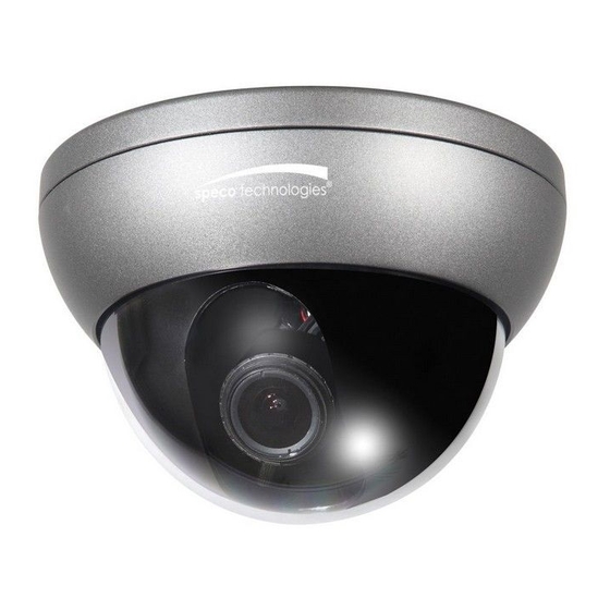
(Indoor Wall & Ceiling Mount Dome Camera)
(Indoor Wall & Ceiling Mount Dome Camera)
(Traditional Box type Camera)
HT647HRTP
CVC6245IHR
CVC6246IHR
HTINTT5
Rev. 6/20/2012
Advertisement
Table of Contents

Related Manuals for Speco 650Line Intensifier3™ Series


Summary of Contents for Speco 650Line Intensifier3™ Series
- Page 1 (Indoor Wall & Ceiling Mount Dome Camera) CVC6246IHR (Indoor Wall & Ceiling Mount Dome Camera) HTINTT5 (Traditional Box type Camera) Speco Technologies is constantly developing product improvements. We reserve the right to modify product design and specifications without notice and without incurring any obligation. Rev. 6/20/2012...
-
Page 2: Table Of Contents
Contents Contents ............1 ◑ Precautions ..........2, 3 ◑ Safety Instructions ........4 ◑ Package Contents ........5 ◑ Camera Installation ........6-13 ◑ Specifications ..........14-20 ◑ Camera Dimension ........21-23 ◑ Features ............24-25 ◑ OSD Menu Details ........26- 37 ◑... -
Page 3: Precautions
Precautions Do not install the camera in Do not install the camera under Do not touch the front lens of the extreme temperature conditions. unstable lighting conditions. camera. Only use the camera under conditions Severe lighting change or flicker can This is one of the most important parts of where temperatures are between cause the camera to work improperly. - Page 4 CAUTION CAUTION CAUTION RISK OF ELECTRIC SHOCK RISK OF ELECTRIC SHOCK RISK OF ELECTRIC SHOCK DO NOT OPEN DO NOT OPEN DO NOT OPEN CAUTION:TO REDUCE THE RISK OF ELECTRIC SHOCK CAUTION:TO REDUCE THE RISK OF ELECTRIC SHOCK CAUTION:TO REDUCE THE RISK OF ELECTRIC SHOCK DO NOT REMOVE COVER(OR BACK).
-
Page 5: Safety Instructions
Safety Instructions Precautions for use ◑ This camera should be installed by qualified personnel only ◑ There are no user serviceable parts inside ◑ Do not disassemble this camera other than to make initial adjustments ◑ Use a UL approved regulated 24 volt AC or 12 volt DC power supply ◑... -
Page 6: Package Contents
Package Contents Please make sure that the following items are included in the Package: 1) HT7246IHR, HT7247IHR, HT7250IHR • 1 Video Test Connector, Power Jack • 1 Chameleon Cover • 1 Wrench • Set Screw - 3 Tapping Screws 4x40 - 3 Plastic Anchor 2) HTINTB8, HTINTB9, HTINTB10 •... -
Page 7: Camera Installation
CAMERA INSTALLATION... -
Page 8: Camera Installation
CAMERA INSTALLATION Compatibility 1) HT7246IHR, HT7247IHR, HT7250IHR INTWM INTPM CVCJBD 2) HTINTB8, HTINTB9, HTINTB10 CVCJBB INTJBS INTCM... - Page 9 CAMERA INSTALLATION Compatibility 3) HTINTD8, HTINTD9, HTINTD10 INTWM INTPM JB03TG 4) CVC6245IHR, CVC6246IHR...
- Page 10 CAUTION : The installation instructions in this manual are for use by qualified service personnel only. To reduce the risk of electric shock, do not perform any servicing other than that contained in the operating instructions unless you are qualified to do so. CAMERA INSTALLATION 1.
- Page 11 CAMERA INSTALLATION 2. HTINTB8, HTINTB9, HTINTB10 CAMERA ASSEMBLY BASE ADAPTOR BRACKET TAPPING SCREW 4X25, 4EA HEXAGON SOCKET SCREW M5X10, 4EA...
- Page 12 CAMERA INSTALLATION 3. HTINTD8, HTINTD9, HTINTD10 DOME BASE TAPPING SCREW 4X25, 3EA DOME ASSEMBLY HEXAGON SOCKET SCREW M6X20, 2EA DOME BODY...
- Page 13 CAMERA INSTALLATION 4. HT647HRTP BASE & ROTATE BRACKET ASSEMBLY TAPPING SCREW 3X40, 3EA BODY & DOME COVER ASSEMBLY...
- Page 14 CAMERA INSTALLATION 5. CVC6245IHR, CVC6246IHR BASE ASSEMBLY TAPPING SCREW 4X20, 2EA DOME COVER ASSEMBLY...
-
Page 15: Specifications
Auto / Off (Selectable x2 ~ x512) Motion Detection On / Off (8 Programmable Zones) Privacy Masking On / Off (12 Programmable Zones) SPECO DNR On / Off (Level adjustable) Digital Zoom On / Off (x1 ~ x16) DIS (Digital Image Stabilization) - Page 16 Auto / Off (Selectable x2 ~ x512) Motion Detection On / Off (8 Programmable Zones) Privacy Masking On / Off (12 Programmable Zones) SPECO DNR On / Off (Level adjustable) Digital Zoom On / Off (x1 ~ x16) DIS (Digital Image Stabilization)
- Page 17 Auto / Off (Selectable x2 ~ x512) Motion Detection On / Off (8 Programmable Zones) Privacy Masking On / Off (12 Programmable Zones) SPECO DNR On / Off (Level adjustable) Digital Zoom On / Off (x1 ~ x16) DIS (Digital Image Stabilization)
- Page 18 Auto / Off (Selectable x2 ~ x512) Motion Detection On / Off (8 Programmable Zones) Privacy Masking On / Off (12 Programmable Zones) SPECO DNR On / Off (Level adjustable) Digital Zoom On / Off (x1 ~ x16) DIS (Digital Image Stabilization)
- Page 19 Auto / Off (Selectable x2 ~ x512) Motion Detection On / Off (8 Programmable Zones) Privacy Masking On / Off (12 Programmable Zones) SPECO DNR On / Off (Level adjustable) Digital Zoom On / Off (x1 ~ x16) DIS (Digital Image Stabilization)
- Page 20 Auto / Off (Selectable x2 ~ x512) Motion Detection On / Off (8 Programmable Zones) Privacy Masking On / Off (12 Programmable Zones) SPECO DNR On / Off (Level adjustable) Digital Zoom On / Off (x1 ~ x16) DIS (Digital Image Stabilization)
- Page 21 Auto / Off (Selectable x2 ~ x512) Motion Detection On / Off (8 Programmable Zones) Privacy Masking On / Off (12 Programmable Zones) SPECO DNR On / Off (Level adjustable) Digital Zoom On / Off (x1 ~ x16) DIS (Digital Image Stabilization)
-
Page 22: Camera Dimension
CAMERA DIMENSION 1) HT7246IHR, HT7247IHR, HT7250IHR 5.10” dia 5.10” dia 3.93” dia 2) HTINTB8, HTINTB9, HTINTB10 11.02” 3.46” 5.90” 5.03” 10.51”... - Page 23 CAMERA DIMENSION 3) HTINTD8, HTINTD9, HTINTD10 5.47” dia 4) HT647HRTP 4.33” dia 4.33” dia 3.22” dia...
- Page 24 CAMERA DIMENSION 5) CVC6245IHR, CVC6246IHR 5.51” dia 5.51” dia 4.60” dia 6) HTINTT5 3.46” 2.51” 3.26”...
-
Page 25: Features
High quality Pictures to be captured in very low light condition. More Powerful WDR in strong back lighting. Your camera allows you to get a clear image. SPECO DNR The Intensifier camera has a DSP chip that can remove image noise efficiently showing clean images in low light conditions. -
Page 26: Features
FEATURES Motion Detection with Alarm Output Built in motion detector with adjustable areas of coverage will Send a signal to an external alarm device when motion is detected. Privacy Mask It also has the ability to mask up to 8 areas of the picture where Viewing is not desired. -
Page 27: Osd Menu Details
Preset Mode ● SPECO TECH 1.PRESET MODE INDOOR 2.MAIN SETUP 3.EXIT RESET 1. Preset : INDOOR / OUTDOOR / LOW LIGHT / HALLWAY / LOBBY / ELEVATOR. - Used for a quick and easy setup for the installation environment. Menu Setup ●... -
Page 28: Exposure Setting
MAIN SETUP 1.LENS 2.EXPOSURE 3.WHITE BAL 3. THE Lens mode has sub menu items as listed below. - BRIGHTNESS : Adjusts the video brightness. - FOCUS ADJ : To adjust the DC lens focus correctly, you must activate the Focus Settings mode under each lens menu. - Page 29 ☞ NOTE ■ When the SHUTTER is set to MANUAL or A.FLK mode, INTENSIFY will be disabled. ◆ FUTO GAIN CONTROL) : The higher the gain level, the brighter the screen - but the higher the noise. * OFF : Deactivates the AGC function. * LOW : Allows automatic gain control from 5.3dB to 32dB.
-
Page 30: Wdr Setting
※ Select one of the following 5 modes, as appropriate for your purpose. ◆ ATW : Select this when the color temperature is between 1,700˚K and 11,000˚K. ◆ OUTDOOR : Select this when the color temperature is between 1,700˚K and 11,000˚K. (sodium light inclusion) ◆... -
Page 31: Backlight Setting
Setup switch so that the arrow indicates 'BACKLIGHT'. MAIN SETUP 1.LENS 2.EXPOSURE 3.WHITE BAL 4.WDR 5.BACKLIGHT 6.SPECO DNR 7.DAY/NIGHT AUTO 8.SPECIAL 9.RETURN SAVE 2. Select a desired mode using the Function Setup switch. ◆ BLC : Enables a user to directly select a desired area from a picture, and to view the area more clearly. -
Page 32: Speco Dnr Setting
SPECO DNR Setting ● This function reduces the background noise in a low luminance environment. 1. When the SETUP menu screen is displayed, select 'SPECO DNR' by using the Function Setup switch so that the arrow indicates 'SPECO DNR'. MAIN SETUP 1.LENS... - Page 33 ☞ NOTE ■ You cannot set the SPECO DNR to ‘ON’ or ‘OFF’ when the AGC mode of the EXPOSURE menu is ‘OFF’. ■ When adjusting the noise reduction level in the SPECO DNR mode, remember that the higher the level set, the more the noise level will be reduced, as will the brightness of the image.
-
Page 34: Special Setting
Special Setting ● 1. When the SETUP menu screen is displayed, select 'SPECIAL' by using the Function Setup switch so that the arrow indicates 'SPECIAL'. MAIN SETUP 1.LENS 2.EXPOSURE 3.WHITE BAL 4.WDR 5.BACKLIGHT 6.SPECO DNR 7.DAY/NIGHT AUTO 8.SPECIAL 9.RETURN SAVE... - Page 35 2. Select a desired mode using the Function Setup switch. SPECIAL 1.IMAGE ADJ 2.MONITOR 3.CAM TITLE 4.SYNC 5.MOTION DET 6.PRIVACY 7.COMM ADJ 8.LANGUAGE ENGLISH 9.RETURN ◆ IMAGE ADJ. : 1) When the SETUP menu screen is displayed, select 'IMAGE ADJ' by using the Function Setup switch so that the arrow indicates 'IMAGE ADJ'.
- Page 36 ☞ NOTE ■ When the V-REV or H-REV mode is enabled, the text on the screen does not flip. ■ If you increase the SHARPNESS level too high, the picture may become distorted or noise may appear. ◆ MONITOR : Please change the settings value of video appropriate to your monitor. 1) LCD : Please select this menu item when using a LCD monitor.
- Page 37 - INT : Internal Synchronization Type - L/L : Power Synchronization Type, Line-lock * Press the Function Setup switch. * You can select a desired phase from 0 to 359 when select 'phase'. ☞ NOTE ■ When using AC power at 60Hz(NTSC), 50Hz(PAL), frequency, you can use the L/L type synchronization.
-
Page 38: Return Setting
1) When the SPECIAL menu screen is displayed, press the Function Setup switch so that the arrow indicates 'PRIVACY'. 2) Set up the mode using the Function Setup switch. - AREA : You can select up to 12 PRIVACY areas. - MODE : Determines whether to use the area selected in the AREA. -
Page 39: Trouble Shooting
Trouble Shooting ● PROBLEM POSSIBLE CAUSE FCheck the power cable, power supply output and video Northing appears on connection between the camera and monitor. the screen. FAre the camera lens or the lens glass dirty? Clean the lens / glass with a soft clean cloth. The image on the FAdjust the monitor controls, as required. - Page 41 uMEMO...
- Page 42 uMEMO...
- Page 43 uMEMO...
- Page 44 200 New Highway Amityville, NY 11701 631-957-8700 1 800 645 5516 www.specotech.com...
Need help?
Do you have a question about the 650Line Intensifier3™ Series and is the answer not in the manual?
Questions and answers