Sign In
Upload
Download
Table of Contents
Contents
Add to my manuals
Delete from my manuals
Share
URL of this page:
HTML Link:
Bookmark this page
Add
Manual will be automatically added to "My Manuals"
Print this page
×
Bookmark added
×
Added to my manuals
Manuals
Brands
ASROCK Manuals
Motherboard
EP2C606-4L/D16
User manual
ASROCK EP2C606-4L/D16 User Manual
Hide thumbs
1
2
Table Of Contents
3
4
5
6
7
8
9
10
11
12
13
14
15
16
17
18
19
20
21
22
23
24
25
26
27
28
29
30
31
32
33
34
35
36
37
38
39
40
41
42
43
44
45
46
47
48
49
50
51
52
53
54
55
56
57
58
59
60
61
62
63
64
65
66
67
68
69
70
71
72
73
74
75
76
77
78
79
80
81
82
83
84
85
86
87
88
89
90
91
92
93
94
95
96
97
98
99
page
of
99
Go
/
99
Contents
Table of Contents
Troubleshooting
Bookmarks
Table of Contents
User Manual
Copyright Notice
Table of Contents
1 Introduction
Package Contents
Specifications
Motherboard Layout
I/O Panel
Block Diagram
2 Installation
Pre-Installation Precautions
Screw Holes
CPU Installation
Installation of Heatsink and CPU Fan
Installation of Memory Modules (DIMM)
Expansion Slots (PCI and PCI Express Slots)
Installing an Expansion Card
Jumpers Setup
Onboard Headers and Connectors
Fan Connectors
Cpu Fan Connectors
Driver Installation Guide
Hot Plug for Hard Disk Drives
3 Uefi Setup Utility
Introduction
UEFI Menu Bar
Navigation Keys
Main Screen
Advanced Screen
ACPI Configuration
WHEA Configuration
CPU Configuration
North Bridge Configuration
South Bridge Configuration
USB Configuration
Intel ME Subsystem
Clock Generator Configuration
Storage Configuration
Super IO Configuration
Serial Port Console Redirection
Voltage Control
Hardware Health Event Monitoring Screen
Server Management
Boot Screen
Security Screen
Exit Screen
Event Logs
4 Software Support
Install Operating System
Support CD Information
Running Support CD
Drivers Menu
Utilities Menu
Contact Information
5 Troubleshooting
Troubleshooting Procedures
Technical Support Procedures
Returning Merchandise for Service
Advertisement
Quick Links
1
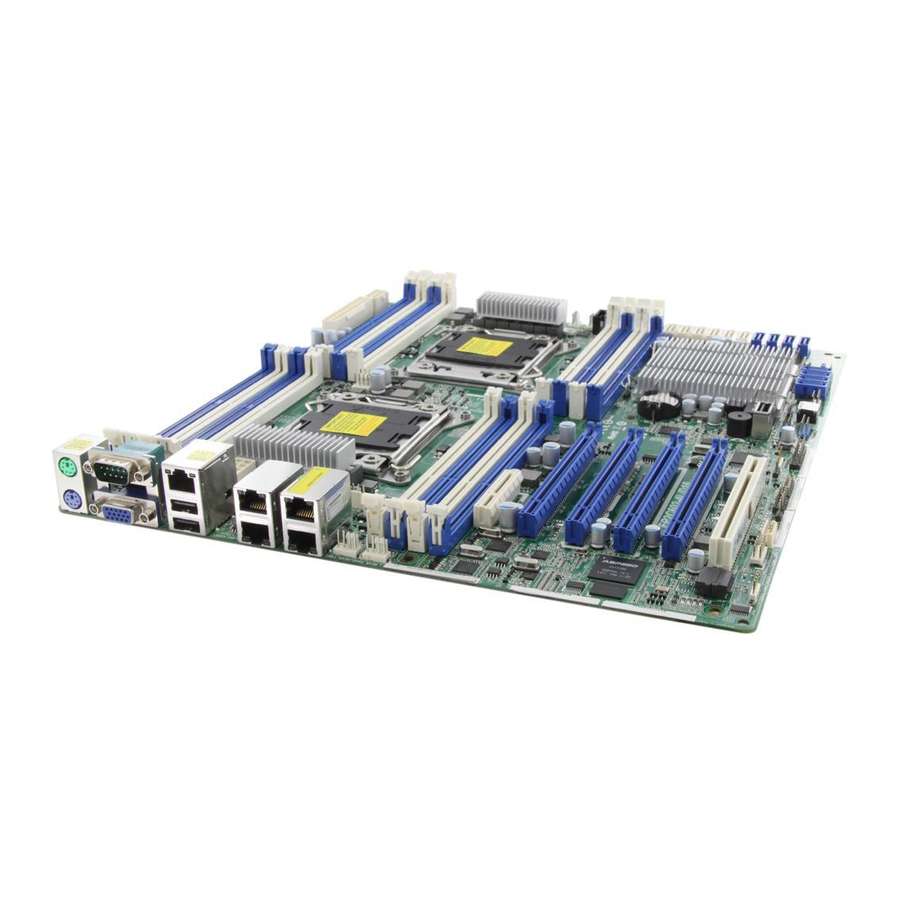
Motherboard Layout
2
I/O Panel
3
Installation of Memory Modules (DIMM)
4
Troubleshooting Procedures
Download this manual
EP2C606-4L/D16
EP2C602-4L/D16
EP2C602/D16
EP2C606-4L
EP2C602-4L
EP2C602
User Manual
Published Jan 2013
Copyright©2013 ASRock INC. All rights reserved.
Version 1.0
1
Table of
Contents
Previous
Page
Next
Page
1
2
3
4
5
Advertisement
Table of Contents
Need help?
Do you have a question about the EP2C606-4L/D16 and is the answer not in the manual?
Ask a question
Questions and answers
Related Manuals for ASROCK EP2C606-4L/D16
Motherboard ASRock EP2C602 Series User Manual
(102 pages)
Motherboard Asrock EP2C602-4L/D16 User Manual
(99 pages)
Motherboard Asrock EP2C602-4L User Manual
(99 pages)
Motherboard ASROCK EP2C602D16FM User Manual
(78 pages)
Motherboard ASROCK EP2C612D16-4L User Manual
Server/workstation motherboard (91 pages)
Motherboard ASROCK EP2C612D16FM User Manual
Asrock server/workstation motherboard (95 pages)
Motherboard ASROCK EP2C612D8 User Manual
Ep2c612d8 series (88 pages)
Motherboard ASRock RACK EP2C612D16C-4L User Manual
Server/workstation (92 pages)
Motherboard ASROCK EP2C612D16T-4L User Manual
(89 pages)
Motherboard ASROCK EP2C612 WS User Manual
(104 pages)
Motherboard ASROCK EP2C612D8C User Manual
Server/workstation (82 pages)
Motherboard ASROCK EP2C612D16SM User Manual
(91 pages)
Motherboard ASROCK EP2C612D24-4L User Manual
Server/workstation motherboard (96 pages)
Motherboard ASROCK EP2C622D16FM User Manual
Server/workstation motherboard (89 pages)
Motherboard ASROCK EP2C622D24LM User Manual
(97 pages)
Motherboard ASROCK EP2C622D24LM2 User Manual
Server/workstation motherboard (91 pages)
This manual is also suitable for:
Ep2c602-4l/d16
Ep2c602
Ep2c602/d16
Ep2c606-4l
Ep2c602-4l
Table of Contents
Print
Rename the bookmark
Delete bookmark?
Delete from my manuals?
Login
Sign In
OR
Sign in with Facebook
Sign in with Google
Upload manual
Upload from disk
Upload from URL


Need help?
Do you have a question about the EP2C606-4L/D16 and is the answer not in the manual?
Questions and answers