Table of Contents
Advertisement
Chapter of Contents
Chapter of Contents
Chapter of Contents................................................................................................ 1
1.1 A Thank-you Note Before You Get Started............................................... 3
1.2 The Features Of This Manual .................................................................. 4
1.3 Preliminary Tools ...................................................................................... 5
Chapter 2 What's In The Box?................................................................................ 6
2.1 What's In The Box? .................................................................................. 6
2.2 Accessory ................................................................................................. 7
2.3 What Specification Do We Got here?....................................................... 8
2.4 What Features bundled here?................................................................ 10
Chapter 3 Start To Assemble ................................................................................ 11
3.1 Features of XC cube .............................................................................. 11
3.2 Starting installing .................................................................................... 12
3.3 Cooler, Hard Disk, Floppy Drives and DVD-RW devices....................... 12
3.3.1 Taking Cooler out........................................................................ 12
3.3.2 Install Hard disk .......................................................................... 15
3.3.3 Install Floppy Drive ..................................................................... 15
3.3.4 Install DVD-RW Drive ................................................................. 15
3.4 Cables and Connectors.......................................................................... 16
3.5 Install CPU, CPU Cooler and CPU Fan Connector ............................... 18
3.6 Connecting DRAM to DIMM Sockets ..................................................... 20
3.7 Insert AGP card or PCI card to motherboard ......................................... 21
3.8 Putting Drives Cage back to Chassis..................................................... 22
3.9 All Set ..................................................................................................... 23
3.10 How about all external peripheral? ...................................................... 24
Chapter 4 Turn On The Power!............................................................................. 28
1
Advertisement
Table of Contents

Subscribe to Our Youtube Channel
Related Manuals for AOpen XCube


Summary of Contents for AOpen XCube
-
Page 1: Table Of Contents
Chapter of Contents Chapter of Contents Chapter of Contents....................1 1.1 A Thank-you Note Before You Get Started..........3 1.2 The Features Of This Manual ..............4 1.3 Preliminary Tools ..................5 Chapter 2 What’s In The Box?................6 2.1 What’s In The Box? .................. 6 2.2 Accessory .................... - Page 2 Chapter 5 Wonderful Feature Provided From AOpen........... 32 Postscripts......................34 Appendix ....................... 35...
-
Page 3: A Thank-You Note Before You Get Started
We regret not informing about any changes in usage standards and other related information. AOpen Company reserves the right of altering or modifying the content of this manual. In case of any mistakes or incorrect descriptions, which include those on the products, AOpen makes no guarantee or commitments. -
Page 4: The Features Of This Manual
1.2 The Features Of This Manual In this manual, you'll be able to learn how to: set up a personal computer on your own. correctly and safely put everything together and learn something about hardware. learn some practical techniques that make doing the job easier. In addition, this manual DOES NOT offer you: any sorts of back doors, such as overclocking. -
Page 5: Preliminary Tools
1.3 Preliminary Tools "A workman must first sharpen his tools if he is to do his work well". Right before you start the assembly, there are some tools that can't be spared. Firstly, the most frequently-used too is cross screwdriver by which most interior components are fixed. -
Page 6: Chapter 2 What's In The Box
Chapter 2 What’s In The Box? Chapter 2 What’s In The Box? 2.1 What’s In The Box? Open the XCcube box, you will finds components as follow: XCcube chassis / Drives Cage Motherboard Power Supply CPU cooler All in One Drives Cage Power Supply / XC cube chassis Motherboard... -
Page 7: Accessory
2.2 Accessory Beside main components, you are supposed to see the following accessories: Fixed screws: After opening the accessory parcel, you'll see the following four different type of screws: As shown in the picture, As shown in the picture, the NO.3 threads NO.1... -
Page 8: What Specification Do We Got Here
2.3 What Specification Do We Got here? This XCcube comes with two type of motherboard for your selection. Let’s take a brief look at what specification these two boards got. For Intel lover, we provide UX4SG-1394 here. Please refer to the Appendix chapter for motherboard details. AC’97 CODEC Front Audio Back Panel... - Page 9 For Pro- AMD user, we provide UK79G-1394. Please refer to the Appendix chapter for motherboard details. Back Panel Front Audio AC’97 CODEC IEEE1394 x 2 USB connectors x 2 ATX Power PCI slot FDD Connector AGP 8X SYSFAN3 SYSFAN2 462-pin CPU Socket that supports AMD Athlon / Duron / and nForce2-GT...
-
Page 10: What Features Bundled Here
2.4 What Features bundled here? One of the advantages of AOpen motherboard is its inventive features, which bundled along with their models. Various features had been included in UX4SG-1394 (EZ65) and UK79G-1394 (EZ18) motherboard. You may directly visit our technical website for details: http://english.aopen.com.tw/tech/techinside... -
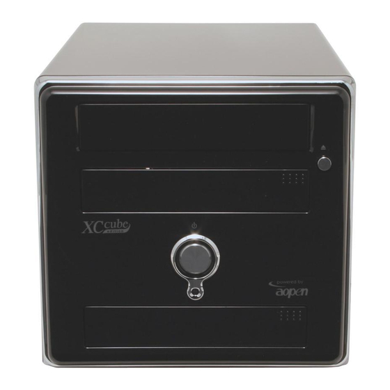
Page 11: Chapter 3 Start To Assemble
PC design that obviously highlighted your individual style and taste with different color panel provided. In addition to it’s unique appearance, AOpen XC cube is easy to move around in your house, suitable for decoration even in your living room. As light and crispy as it is, it is definitely your choice for a PC. -
Page 12: Starting Installing
3.2 Starting installing Unscrew all screws on the chassis. Use your thumb to push the chassis backward to you. Lift the chassis up. Here you may see the internal of the chassis. 3.3 Cooler, Hard Disk, Floppy Drives and DVD-RW devices 3.3.1 Taking Cooler out Before installing hard disk, floppy drives and DVD-RW into the XC cube chassis, let’s take the cooler out from chassis first. - Page 13 Take the screws off the chassis and then take the Drives Cage out. Drives Cage For EZ65 XC cube PC,. Before taking AOpen-made Cooler out, please disconnect its connector first. After that, unfasten AOpen-made Cooler. Pull the iron plate up and relieve it from the hook of retention module.
- Page 14 Therefore, please kindly pay attention to the FRONT mark shown in the picture. For EZ18 XC cube PC. Before taking AOpen-made Cooler out, please disconnect its connector first. After that, unfasten AOpen-made Cooler. Use a screwdriver to push the iron lock down to relieve it from the socket.
-
Page 15: Install Hard Disk
3.3.2 Install Hard disk After taking out Cooler, let’s focus on Installing Drives Cage. Slide hard disk into the Drives Cage, and use screw no. 3 to screw it firmly to the cage. Heat dissipation side face up. Front mark Front mark 3.3.3 Install Floppy Drive Slide in the floppy drive as shown. -
Page 16: Cables And Connectors
Don't mess up screws!! Generally there are special screws for hard disk in the parcel when you buy a new hard disk. There will be no harm done using those screws. If no screws are attached, use those packed in the accessory parcel. - Page 17 You might have to pull Front Panel Floppy Cable aside a bit drive to find the FDD cable connector. If you happen to have Serial ATA hard disk, this motherboard comes with Serial ATA connectors onboard as well. With EzColor design, you may easily find out the correct flame-red cable with the correct header.
-
Page 18: Install Cpu, Cpu Cooler And Cpu Fan Connector
3.5 Install CPU, CPU Cooler and CPU Fan Connector Erect sensor up a bit (it might have been folded while shipped in with Cooler on top of it). After that, erect CPU socket lever up. Lever Sensor Install CPU onto the CPU bracket. Press the lever back to CPU socket. And it’s done. - Page 19 For EZ65 XC cube. Put CPU cooler firmly onto the CPU retention module. The vertical side Cooler must be faced to this side shown. Connect the fan cable onto the CPU FAN connector onboard. Evenly press the iron plate downward till you hear a “clip” sound UX4SG-1394 motherboard CPU Fan connector For EZ18 XC cube.
-
Page 20: Connecting Dram To Dimm Sockets
Connect the fan cable onto the fan connector onboard. Lock the right iron plate of cooler to the socket as shown. UX4SG-1394 motherboard CPU Fan connector Use screwdriver to press the iron plate downward till the iron plate is firmly hooked to socket. 3.6 Connecting DRAM to DIMM Sockets DIMM socket is designed in Sky Blue color, which is very easy to recognize. -
Page 21: Insert Agp Card Or Pci Card To Motherboard
3.7 Insert AGP card or PCI card to motherboard If you happen to have AGP card or PCI, you may insert them onto the AGP slot as shown. Screw the iron plate off the back panel, and use the screwdriver to pry it out. After that, please plug in the AGP card. -
Page 22: Putting Drives Cage Back To Chassis
3.8 Putting Drives Cage back to Chassis Putting all cables aside, and assemble the Drives Cage back to the chassis from top of the chassis. Lift the Drive Cage up at 45 degree for better installing DVD-RW and Floppy Drive. Connecting Floppy drive and its power cord to Drive Cage: Connecting DVD-RW drive/power cord to Drive Cage:... -
Page 23: All Set
Connecting hard disk/power cord to Drive Cage: Lock the Drives Cage with screw No. 2. 3.9 All Set Assemble the housing back to the chassis. Screw the chassis back. -
Page 24: How About All External Peripheral
3.10 How about all external peripheral? Let’s take a look at the Front Panel and Back Panel ports. Back Panel – EZ65 XC cube IEEE1394 connector Coaxial RCA Port Ethernet network COM1 connecto (RJ-45) Printer Port Line-In Jack Multimedia speaker jack PS/2 mouse Microphone jack... -
Page 25: Front Panel
Front Panel Optical Devices Floppy Drive/Card Reader On/Off button IEEE1394 port IEEE1394 port (4-pin) USB2.0 ports S/PDIF Out port Speaker jack Microphone jack keyboard and mouse Connect monitor and tighten screws Connect... - Page 26 Microphone (speaker or earphone) and network cable Connect voltage power supply cable. Set proper and connect The voltage supplied by power outlet differs from countries or areas you dwell in. If the outlet is supplied by 110V, please set the switch to 115V. If the outlet is supplied by 220V, please set the switch to 230V.
- Page 27 [Note]...
-
Page 28: Chapter 4 Turn On The Power
Delete button: Phoenix-AwardBIOS BIOS v6.00PG, An Energy Star Ally Copyright (C) 2003, Phoenix Technologies, LTD. L210 R0.05 July.16.2003 AOpen Inc. Main Processor : AMD Ahtlon(tm) XP 3000+ Memory Testing : 491520K OK + 32M Shared Memory DDR Dual Channel Enabled... - Page 29 After pressing Delete, you'll see the following BIOS setup: Now, you can move the cursor by using direction keys on the keyboard. Move the cursor to the option item "Load Setup defaults" and press Enter...
- Page 30 Then, the following dialogue screen will pop up to confirm the default BIOS values. Please press "Y" to confirm and then press Enter Finally, move the cursor to "Save & Exit Setup" and press Enter to save the parameters and exit BIOS setup.
- Page 31 At the same time, type "Y" in the dialogue box and press Enter to exit. Now everything is perfectly finished!!
- Page 32 Chapter 5 Wonderful Feature Provided From AOpen Chapter 5 Wonderful Feature Provided From AOpen Except its unique appearance and its flexibility in moving, XC cube is equipped with many creative and practical features. Simply introduce one of our wonderful features -- SilentTek.
- Page 33 Multiple Level Control: This is the most versatile setting that allows you to set fan speed in relation to temperature. AOpen Recommend Setting: This setting is designed specifically for AOpen housing. A series of lab tests were conducted under the...
- Page 34 We sincerely hope every customer who wants to assemble a computer on his or her own has a wonderful beginning! To learn more about AOpen XC cube, visit us at xc.aopen.com.tw P/N:49.EZ101.0A1 Doc.no:EZ65EZ18B-OL-E0309A...
- Page 35 Appendix Appendix AOpen XC cube comes with two versions of motherboard for your selection, they are separately UX4SG-1394 (EZ65) and UK79G-1394 (EZ18). To get to know the details of them, please refer to their respective information as below. UX4SG-1394 Motherboard...
- Page 36 DIMM sockets UX4SG-1394 allow you to install 128-bit dual channel DDR400, DDR333 or DDR266 memory up to 2GB. Only non-ECC DDR RAM is supported. Please install suitable modules; otherwise serious damage may occur on memory sockets or you RAM modules. Please note that when you install DDR333 memory module and have your CPU FSB set at 800MHz, the memory can only run with speed DDR320.
- Page 37 CPU and System Fan Connector Plug in the CPU fan cable to the 3-pin CPUFAN1 connector. If you have chassis fan, you can also plug it on SYSFAN2 or SYSFAN3 connector. SYSFAN3 connector +12V SENSOR CPUFAN connector SYSFAN2 connector Connecting Serial ATA Connector To connect a Serial ATA disk, you must use a 7-pin serial ATA cable.
- Page 38 UK79G-1394 Motherboard Full-range Adjustable CPU Core Voltage This motherboard supports CPU VID function. The CPU core voltage will be automatically detected and the range is from 1.1V to 1.85V. It is not necessary to set CPU Core Voltage. Setting CPU Frequency This motherboard is CPU jumper-less design, you can set CPU frequency through the BIOS setup, and no jumpers or switches are needed.
- Page 39 DIMM sockets This motherboard supports DDR400/333/266 with Maximum capacity up to 2GB (When enabling VGA onboard, memory can run max. up to 333MHz). Only Non-ECC DDR RAM is supported, otherwise, it will cause serious damage on memory sockets or SDRAM module. For over clocking purpose, you can adjust memory voltage in BIOS from 2.5V to 2.65V.
- Page 40 JP15/JP16 Dr. Voice Language Select Jumpers Dr. Voice is a great feature, which can identify the problems you may encounter in the operating system. It can clearly “tell you” whether the problem is caused from components or improper installation such as CPU, memory module, VGA, PCI add-on card, FDD, HDD or keyboard. Dr. Voice provides four language versions: English, German, Japanese and Chinese.
Need help?
Do you have a question about the XCube and is the answer not in the manual?
Questions and answers