Table of Contents
Advertisement
Quick Links
Trace Oxygen Analyzer
OPERATING INSTRUCTIONS
3010
TB
Model
Trace Oxygen Analyzer
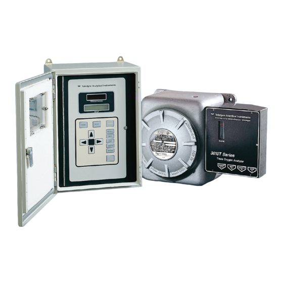
Bulkhead Mount Control Unit, PN D-66190A*
NEC Type Analysis Unit, PN D-65478*
DANGER
HIGHLY TOXIC AND OR FLAMMABLE LIQUIDS OR GASES MAY BE PRESENT IN THIS MONITORING
SYSTEM.
PERSONAL PROTECTIVE EQUIPMENT MAY BE REQUIRED WHEN SERVICING THIS SYSTEM.
HAZARDOUS VOLTAGES EXIST ON CERTAIN COMPONENTS INTERNALLY WHICH MAY PERSIST
P/N M62927
FOR A TIME EVEN AFTER THE POWER IS TURNED OFF AND DISCONNECTED.
11/24/04
ONLY AUTHORIZED PERSONNEL SHOULD CONDUCT MAINTENANCE AND/OR SERVICING. BEFORE
CONDUCTING ANY MAINTENANCE OR SERVICING CONSULT WITH AUTHORIZED SUPERVISOR/
ECO: #03-0126
MANAGER.
i
Teledyne Analytical Instruments
Advertisement
Chapters
Table of Contents

Related Manuals for Teledyne 3010TB


Summary of Contents for Teledyne 3010TB
-
Page 1: Operating Instructions
HAZARDOUS VOLTAGES EXIST ON CERTAIN COMPONENTS INTERNALLY WHICH MAY PERSIST P/N M62927 FOR A TIME EVEN AFTER THE POWER IS TURNED OFF AND DISCONNECTED. 11/24/04 ONLY AUTHORIZED PERSONNEL SHOULD CONDUCT MAINTENANCE AND/OR SERVICING. BEFORE CONDUCTING ANY MAINTENANCE OR SERVICING CONSULT WITH AUTHORIZED SUPERVISOR/ ECO: #03-0126 MANAGER. Teledyne Analytical Instruments... - Page 2 Any safeguards required such as locks, labels, or redundancy, must be provided by the user or specifically requested of Teledyne at the time the order is placed.
- Page 3 Trace Oxygen Analyzer Table of Contents Specific Model Information ......... iv Preface ..............v Part I: Control Unit, Model TB ....Part I: 1-1 Part II: Analysis Unit, Model T ....Part II: 1-1 Appendix ............A-1 Teledyne Analytical Instruments...
- Page 4 Model 3010TB Specific Model Information The instrument for which this manual was supplied may incorporate one or more options not supplied in the standard instrument. Commonly available options are listed below, with check boxes. Any that are incorpo- rated in the instrument for which this manual was supplied are indicated by a check mark in the box.
-
Page 5: Typical Applications
Analysis Unit, or remote probe, that can operate in a hazardous area. Part I of this manual covers the Model 3010TB General Purpose NEMA 4 Bulkhead mount Control Unit only. This Control Unit is for outdoor/indoor use in a nonhazardous environment. - Page 6 Model 3010TB Model and Part Number Designations The part numbers are the most specific identification. When using this manual for operation, maintenance, or ordering parts, check the part num- bers on your Instruments to be sure of a match. Where an underscore (_) appears in a model number, the unit has more than one application.
-
Page 7: Main Features Of The Analyzer
Trace Oxygen Analyzer Main Features of the Analyzer The Model 3010TB series Oxygen Analyzers are sophisticated yet simple to use. The main features of these analyzers include: • A 2-line alphanumeric display screen, driven by microprocessor electronics, that continuously prompts and informs the operator. - Page 8 Model 3010TB viii Teledyne Analytical Instruments...
- Page 9 Part I: Control Unit OPERATING INSTRUCTIONS 3010 TB Model Oxygen Analyzer Part I: Control Unit NEMA 4 Bulkhead Mount Part Numbers: D-66190A Teledyne Analytical Instruments Part I: i...
-
Page 10: Table Of Contents
Model 3010TB Oxygen Analyzer Table of Contents 1 Introduction 1.1 Overview ................ 1-1 1.2 Control Unit Inner Control Panel ........1-1 1.3 Recognizing Difference Between LCD & VFD ....1-3 1.4 Control Unit Interface Panel ........... 1-4 2 Operational Theory 2.1 Introduction .............. - Page 11 4.8 Signal Output ..............4-21 5 Maintenance 5.1 Fuse Replacement............5-1 5.2 System Self Diagnostic Test ........... 5-2 5.3 Major Internal Components ..........5-3 5.4 Cleaning ................ 5-4 A Appendix Model 3010TB Specifications ..........A-3 Part I: iii Teledyne Analytical Instruments...
- Page 12 Model 3010TB Oxygen Analyzer iv: Part I Teledyne Analytical Instruments...
-
Page 13: Operational Theory
(PCB) assemblies inside the Control Unit chassis. The PCB locations are illustrated in section 5, Maintenance. Refer to Figure 2-1, Block Diagram of the 3010TB CU Electronics: In the presence of oxygen, the sensor (in the Analysis Unit) generates a current. - Page 14 2 Operational Theory Model 3010TB Figure 2-1: Block Diagram of the 3010TB CU Electronics 2-2: Part I Teledyne Analytical Instruments...
- Page 15 4-20 mA dc and the 0-1 V dc analog concentra- tion signal outputs, and the analog range ID outputs. The microprocessor monitors the power supply, and activates the system failure alarm if a malfunction is detected. Part I: 2-3 Teledyne Analytical Instruments...
- Page 16 2 Operational Theory Model 3010TB 2-4: Part I Teledyne Analytical Instruments...
-
Page 17: Installation
This Unit is NOT for any type of hazardous environments. The standard model is designed for indoor/outdoor mounting. Figure 3- 1 is an illustration of a Model 3010TB standard Control Unit front panel and mounting brackets located-two at the top and two at the bottom of the units frame. - Page 18 3 Installation Model 3010TB NPT Fittings supplied by custom er Viewing W indow % Anlz AL -1 AC POWER IN 3/4" NPT 50/60 HZ 100-240V Outer Door Latch 3/4" NPT ALARM OUTPUTS DIGIT AL INPUT SP AN ZERO CAL. CONT ACT RANGE 1"...
-
Page 19: Electrical Connections
Stripped wire ends must insert completely into terminal blocks. No uninsulated wiring should be able to come in contact with fingers, tools or clothing during normal operation. Part I: 3-3 Teledyne Analytical Instruments... -
Page 20: Primary Input Power
3 Installation Model 3010TB Primary Input Power: The universal power supply requires a 100- 240V ac, 50/60 Hz power source. See Figure 3-4 for detailed connections. DANGER: Power is applied to the instrument's circuitry as long as the instrument is connected to the power source. - Page 21 For example, if the analyzer is set on a range that was defined as )-10 % O2, then the output would be as shown in Table 3-1. Table 3-1: Analog Concentration Output-Examples Part I: 3-5 Teledyne Analytical Instruments...
- Page 22 3 Installation Model 3010TB Voltage Signal Current Signal Output (V dc) Output (mA dc) 10.4 12.0 13.6 15.2 16.8 18.4 20.0 To provide an indication of the range, a second pair of analog output terminals are used. They generate a steady preset voltage (or current when using the current outputs) to represent a particular range.
- Page 23 Cannot be de- feated. Actuates if self test fails. To reset a System Alarm during installation, discon- nect power to the instrument and then reconnect it Further detail can be found in chapter 4, section 4-5. Part I: 3-7 Teledyne Analytical Instruments...
- Page 24 (See Remote Calibration Protocol below.) Remote Calibration Protocol: To properly time the Digital Remote Cal Inputs to the Model 3010TB Analyzer, the customer's controller must monitor the Cal Relay Contact. When the contact is OPEN, the analyzer is analyzing, the Remote Cal Inputs are being polled, and a zero or span command can be sent.
- Page 25 If you have the -C Internal valve option - which includes additional zero and span gas inputs - the 3010TB automatically regulates the zero, span and sample gas flow. Range ID Relays: Four dedicated RANGE ID CONTACT relays .
- Page 26 Toggling input. Stops/Starts any status message output from the RS-232, Until st<enter> is sent again. The RS-232 protocol allows some flexibility in its implementation. Table 3-5 lists certain RS-232 values that are required by the 3010TB. Table 3-5: Required RS-232 Options Parameter...
- Page 27 Note that each individual line has a series FET with a nominal ON resistance of 5 ohms (9 ohms worst case). This can limit the obtainable voltage, depending on the load impedance applied. See Figure 3-9. Figure 3-9: FET Series Resistance Part I: 3-11 Teledyne Analytical Instruments...
-
Page 28: Testing The System
3 Installation Model 3010TB Testing the System After The Control Unit and the Analysis Unit are both installed and interconnected, and the system gas and electrical connections are complete, the system is ready to test. Before plugging either of the units into their respective power sources: •... -
Page 29: Operation
If you choose not to use password protection, the default password is automatically displayed on the password screen when you start up, and you simply press Enter for access to all functions of the analyzer. Part I: 4-1 Teledyne Analytical Instruments... -
Page 30: Using The Data Entry And Function Buttons
4 Operation Model 3010TB Using the Data Entry and Function Buttons Data Entry Buttons: The < > arrow buttons select options from the menu currently being displayed on the VFD screen. The selected option blinks. When the selected option includes a modifiable item, the Δ Δ Δ Δ Δ ∇ arrow buttons can be used to increment or decrement that modifiable item. -
Page 31: The System Function
PSWD: Security can be established by choosing a 5 digit • password (PSWD) from the standard ASCII character set. (See Installing or Changing a Password, below, for a table of ASCII characters available.) Once a unique password is assigned and Part I: 4-3 Teledyne Analytical Instruments... -
Page 32: Tracking The O Readings During Calibration
4 Operation Model 3010TB activated, the operator MUST enter the UNIQUE password to gain access to set-up functions which alter the instrument's operation, such as setting the instrument span or zero setting, adjusting the alarm setpoints, or defining analysis ranges. -
Page 33: Setting Up An Auto-Cal
Note: If you require highly accurate Auto-Cal timing, use external Auto-Cal control where possible. The internal clock in the Model 3010TB is accurate to 2-3 %. Accordingly, internally scheduled calibrations can vary 2-3 % per day. To setup an Auto–Cal cycle: Choose System from the Function buttons. -
Page 34: Password Protection
4 Operation Model 3010TB TRAK/HLD Auto—Cal PSWD Logout More , and press Enter. A new screen for Use < > arrows to blink Auto—Cal Span/Zero set appears. Span OFF Nxt: 0d 0h Zero OFF Nxt: 0d 0h ), then press Enter again. (You Press <... -
Page 35: Installing Or Changing The Password
If you want to install a password, or change an existing password, proceed as above in Entering the Password. When you are given the oppor- tunity to change the password: Change Password? <ENT>=Yes <ESC>=No Part I: 4-7 Teledyne Analytical Instruments... - Page 36 4 Operation Model 3010TB Press Enter to change the password (either the default TETAI or the previously assigned password), or press Escape to keep the existing pass- word and move on. If you chose Enter to change the password, the password assignment screen appears.
-
Page 37: Logout
Password Reentered 4.3.5 System Self-Diagnostic Test The Model 3010TB has a built-in self-diagnostic testing routine. Pre- programmed signals are sent through the power supply, output board and sensor circuit. The return signal is analyzed, and at the end of the test the status of each function is displayed on the screen, either as OK or as a number between 1 and 3. -
Page 38: Version Screen
4 Operation Model 3010TB Press the System button to start the System function. TRAK/HLD Auto—Cal PSWD Logout More Use the < > arrow keys to blink More, then press Enter. Version Self—Test Use the < > arrow keys again to move the blinking to the Self–Test function. -
Page 39: The Zero And Span Functions
40 psig or less when turning it back on. Readjust the gas pressure into the analyzer until the flowrate (as read on the Analysis Unit SLPM flowmeter) settles between 0.5 and 2.4 SLPM (approximately 1-5 scfh). Part I: 4-11 Teledyne Analytical Instruments... -
Page 40: Zero Cal
4 Operation Model 3010TB If you are using password protection, you will need to enter your password to gain access to either of these functions. Follow the instructions in sections 4.3.3.2 or 4.3.3.3 to enter your password. Once you have gained clearance to proceed, you can enter the Zero or Span function. -
Page 41: Manual Mode Zeroing
Cell failure in the 3010TB is usually associated with inability to zero the instrument down to a satisfactorily low ppm reading, e.g. cell does not fail if it comes below 5PPM . When this occurs, the 3010TB system alarm trips, and the LCD displays a failure message. -
Page 42: Span Cal
4 Operation Model 3010TB c. Check whether more time is needed for readings to drop to a satisfactory level. This might happen when zero was started from very high PPM level If there are no leaks and the span gas is OK, replace the cell as de- scribed in Part II Analysis Units, chapter 5 Maintenance. -
Page 43: Manual Mode Spanning
Slope on the screen. It takes several seconds for the first Slope value to display. Slope indicates rate of change of the Span reading. It is a sensitive indicator of stability. Part I: 4-15 Teledyne Analytical Instruments... -
Page 44: Span Failure
Consider this before replacing the cell. The Alarms Function The Model 3010TB is equipped with 2 fully adjustable concentration alarms and a system failure alarm. Each alarm has a relay with a set of form C contacts rated for 3 amperes resistive load at 250 V ac. See figure in chapter 3, Installation and/or the Interconnection Diagram included at the back of this manual for relay terminal connections. - Page 45 4.3.3 to enter your password. Once you have clearance to proceed, enter the Alarm function. Press the Alarm button on the front panel to enter the Alarm function. Make sure that AL–1 is blinking. Part I: 4-17 Teledyne Analytical Instruments...
-
Page 46: The Range Function
4 Operation Model 3010TB AL—1 AL—2 Choose Alarm Set up alarm 1 by moving the blinking over to AL–1 using the < > arrow keys. Then press Enter to move to the next screen. AL—1 1000 ppm HI Dft—N Fs—N Ltch—N Five parameters can be changed on this screen: •... -
Page 47: Setting The Analog Output Ranges
Oxygen Analyzer Part I: Control Unit The Model 3010TB is set at the factory to default to autoranging. In this mode, the microprocessor automatically responds to concentration changes by switching ranges for optimum readout sensitivity. If the current range limits are exceeded, the instrument will automatically shift to the next higher range. -
Page 48: Fixed Range Analysis
The Analyze Function When the Analyze function is active, the 3010TB is monitoring the sample gas currently flowing in the Analysis Unit cell block. All undefeated alarms are ready to activate should their respective setpoints be crossed. -
Page 49: Signal Output
Part I: Control Unit Signal Output The standard Model 3010TB Trace Oxygen Analyzer is equipped with two 0-1 V dc analog output terminals accessible on the interface panel (one concentration and one range ID) and two isolated 4-20 mA dc current outputs (one concentration and one range ID). - Page 50 4 Operation Model 3010TB IMPORTANT: In the event of loss of flow through the analyzer, if the vent is vented to a location of high oxygen content, oxygen will back diffuse through the vent line and in most cases quickly saturate the cell with oxygen which...
-
Page 51: Maintenance
WARNING: SEE WARNINGS ON THE TITLE PAGE OF THIS MANUAL. Fuse Replacement The 3010TB requires two 5 x 20 mm, 1.0 A, T type (Slow Blow) fuses. The fuses are located inside the main housing on the Electrical Connector Panel, as shown in Figure 5-3. To replace a fuse: 1. -
Page 52: System Self Diagnostic Test
5 Maintenance Model 3010TB Oxygen Analyzer Figure 5-1: Removing Fuse Block Cap and Fuse from Housing 2. Replace fuse by reversing process in step 1. System Self Diagnostic Test 1. Press the System button to enter the system mode. 2. Use the < > arrow keys to move to More, and press Enter. -
Page 53: Major Internal Components
Amplifier output doesn't match test input Both Failed Major Internal Components The major components in the Control Unit are shown in Figure 5-3. Outer Door Inner Door Teledyne Analytical Instruments Main PCB PreampPCB Display PCB Doors shown removed for clarity... - Page 54 WARNING: HAZARDOUS VOLTAGES EXIST ON CERTA1IN COMPONENTS INTERNALLY WHICH MAY PERSIST FOR A TIME EVEN AFTER THE POWER IS TURNED OFF AND DISCONNECTED. The 3010TB Control Units contain the following major components: • Power Supply • Motherboard (with Microprocessor, RS-232 chip, and Preamplifier PCB) •...
-
Page 55: Part Ii: Analysis Unit
Part II: Analysis Unit OPERATING INSTRUCTIONS 3010 TB Model Oxygen Analyzer Part II: Analysis Unit NEC Type Part Number D-65478 Part II: i Teledyne Analytical Instruments... - Page 56 Model 3010TB Oxygen Analyzer Table of Contents 1 Introduction 1.1 Overview ................ 1-1 1.2 Gas Connector Panel ............. 1-1 1.3 Electrical Connector Panel ..........1-2 2 Operational Theory 2.1 Introduction ..............2-1 2.2 Micro-Fuel Cell Sensors ..........2-1 2.2.1 Principles of Operation........... 2-1 2.2.2 Anatomy of a Micro-Fuel Cell ........
- Page 57 5.2.2 When to Replace a Cell .......... 5-3 5.2.3 Removing the Micro-Fuel Cell ......... 5-4 5.2.4 Installing a New Micro-Fuel Cell ......5-5 5.2.5 Cell Warranty ............5-5 5.3 Fuse Replacement ............5-6 5.4 System Self Diagnostic Test .......... 5-6 Part II: iii Teledyne Analytical Instruments...
- Page 58 Model 3010TB Oxygen Analyzer iv: Part II Teledyne Analytical Instruments...
-
Page 59: Appendix
Sample gas inlet. Controlled (with –C option) by Control Unit via Remote Probe connector. • SPAN IN (On –C Option only) Span gas inlet. Internally valved. Controlled by Control Unit via Remote Probe connector. • EXHAUST Exhaust gas outlet. Teledyne Analytical Instruments Part II: 1-1... -
Page 60: Electrical Connector Panel
(visible in Figure 1-1), and connect to terminals inside the housing. The connectors and controls are described briefly here. They are described in detail in the Installation, Operation, and Maintenance chapters, as appropriate. 1-2: Part II Teledyne Analytical Instruments... - Page 61 Solenoid Valves Terminals that provide all electrical intercon- nections from the Control Unit to the gas control valves. • Sensor Signal Terminals that provide connections from the Micro-Fuel Cell sensor to the Control Unit. Teledyne Analytical Instruments Part II: 1-3...
- Page 62 1 Introduction Model 3010T 1-4: Part II Teledyne Analytical Instruments...
-
Page 63: Operational Theory
Micro-Fuel Cell: In the battery, all reactants are stored within the cell, whereas in the Micro-Fuel Cell, one of the reactants (oxygen) comes from outside the device as a constituent of the sample gas being Part II: 2-1 Teledyne Analytical Instruments... -
Page 64: Anatomy Of A Micro-Fuel Cell
Figure 2-1 shows the external features of a typical cell. Figure 2-1: Micro-Fuel Cell Refer to Figure 2-2, Cross Section of a Micro-Fuel Cell, which illus- trates the following internal description. Figure 2-2. Cross Section of a Micro-Fuel Cell (not to scale) 2-2: Part II Teledyne Analytical Instruments... -
Page 65: Electrochemical Reactions
The current is propor- tional to the amount of oxygen reaching the cathode. It is measured and used to determine the oxygen concentration in the gas mixture. Part II: 2-3 Teledyne Analytical Instruments... -
Page 66: The Effect Of Pressure
In addition, since there is almost no output in the absence of oxygen, the characteristic curve has close to an absolute zero—within ± 1 ppm oxygen. (The electronics is zeroed automatically when the instrument power is turned on.) 2-4: Part II Teledyne Analytical Instruments... -
Page 67: Micro-Fuel Cell "Class
Nominal output in air is 0.5 mA, and 90 % response time is 7 s. Expected life is 12 months. Part II: 2-5 Teledyne Analytical Instruments... -
Page 68: Sample Systems
Gas Control Panel. For metric system installations, 6 mm adapters are supplied. For -Vacuum Service, the restrictor is located downstream of the flowmeter. The restrictor is installed in the exhaust port on the gas panel. 2-6: Part II Teledyne Analytical Instruments... -
Page 69: Installation
Micro-Fuel Cell for replacement. Cell replacement, with an exploded view of the cell block, is de- scribed in chapter 5 Maintenance. Teledyne Analytical Instruments Part II: 3-1... -
Page 70: Gas Connector Panel Connections
The restrictor without the blue sticker is for ;ow pressure and vacuum service. For high pressure (5 to 50 psig) applica- tions, use the restrictor that has a blue sticker on the body. 3-2: Part II Teledyne Analytical Instruments... - Page 71 For a safe connection: 1. Insert the tube into the tube fitting, and finger-tighten the nut until the tubing cannot be rotated freely, by hand, in the fitting. (This may require an additional turn beyond finger-tight.) Teledyne Analytical Instruments Part II: 3-3...
-
Page 72: Electrical Connector Panel
Drawings section at the back of this manual. To access the Panel, remove the explosion-proof cover as described in chapter 5, Mainte- nance. NEVER OPEN THE COVER IN A HAZARDOUS ATMO- SPHERE. THE AREA MUST BE DECLARED TEMPORARILY SAFE BY THE PROPER AUTHORITY FIRST. 3-4: Part II Teledyne Analytical Instruments... - Page 73 Unit's Solenoid Valves and Sensor Signal terminals. See Figure 3-4. It provides signals to control the solenoid valves which regulate the zero, span and sample gas flow, and accepts the sensor and thermistor signals for processing. Teledyne Analytical Instruments Part II: 3-5...
- Page 74 Figure 3-4, above. (See drawing D-64949 for wire recommendations.) Thermistor 1 Sensor Signal 8 Thermistor Thermistor 2 Block Sensor Signal 2 Sensor Return (-) Sensor Sensor Signal 1 Block Sensor Hot (+) Sensor Signal 7 Figure 3-5: Remote Probe Connector Pinouts 3-6: Part II Teledyne Analytical Instruments...
-
Page 75: Installing The Micro-Fuel Cell
After The Control Unit and the Analysis Unit are both installed and interconnected, and the system gas and electrical connections are complete, the system is ready to test. Before plugging either of the units into their respective power sources: Teledyne Analytical Instruments Part II: 3-7... - Page 76 Check that sample pressure is between 3 and 40 psig, according to the requirements of your process. Power up the system, and test it as follows: 1. Repeat the Self-Diagnostic Test as described in Part I, chapter 4, section 4.3.5. 3-8: Part II Teledyne Analytical Instruments...
-
Page 77: Operation
Although the instrument can be spanned using air, a span gas with a known oxygen concentration in the range of 70–90% of full scale of the Teledyne Analytical Instruments Part II:... -
Page 78: System Self Diagnostic Test
4 Operation Model 3010TB range of interest is recommended. Since the oxygen concentration in air is 209,000 ppm, the cell can take a long time to recover if the instrument is used for trace oxygen analysis immediately following calibration in air. -
Page 79: Cell Failure Checks
CELL FAIL/ ZERO HIGH Before replacing the cell: a. Check your span gas to make sure it is within specifications. b. Check for leaks downstream from the cell, where oxygen may be leaking into the system. Teledyne Analytical Instruments Part II:... - Page 80 4 Operation Model 3010TB c. Check whether more time is needed for PPM readings to drop to an acceptable level. This is true when coming down from high level. If there are no leaks and the span gas is OK, replace the cell as de- scribed in Part II: Analysis Units chapter 5, Maintenance.
-
Page 81: Maintenance
The 3010T Analysis Unit contains the following major components: • Micro Fuel Cell • Cell block • Sample system • Electrical Connector Panel • Gas Connector Panel (external) See the drawings in the Drawings section in back of this manual for details. Part II: 5-1 Teledyne Analytical Instruments... -
Page 82: Cell Replacement
5 Maintenance Model 3010TB Figure 5-1: Major Components Cell Replacement The Micro-Fuel Cell is a sealed electrochemical transducer with no electrolyte to change or electrodes to clean. When the cell reaches the end of its useful life, it is replaced. The spent fuel cell should be discarded accord- ing to local regulations. -
Page 83: When To Replace A Cell
Chech whether more time is needed for the PPM readingss to drop to an acceptable level (<5PPM). If there are no leaks and the span gas is OK, replace the cell. Part II: 5-3 Teledyne Analytical Instruments... -
Page 84: Removing The Micro-Fuel Cell
5 Maintenance Model 3010TB 5.2.3 Removing the Micro-Fuel Cell WARNING: DO NOT TOUCH THE SENSING SURFACE OF THE CELL. IT IS COVERED WITH A DELICATE TEFLON MEMBRANE THAT CAN LEAK CAUSTIC AND COR- ROSIVE CHEMICALS WHEN PUNCTURED. The Micro-Fuel cell is located inside the housing in a stainless steel cell block. -
Page 85: Installing A New Micro-Fuel Cell
The cell and holder will fall out in your hand. 5.2.4 Installing a New Micro-Fuel Cell It is important to minimize the amount of time that a Teledyne Trace Oxygen Sensor is exposed to air during the installation process. The quicker... -
Page 86: Cell Warranty
5 Maintenance Model 3010TB Step 8. With O-ring in place, align the guide pin with the hole on the cell holder. Then, with the holder, lift cell into the cell block. Step 9. Push the gate on the cell block down so that the slots on the side of the gate engage the locating screws on the side of the block. -
Page 87: Fuse Replacement
4. Observe the error-code readings on the VFD Display screen, and check Table 5-1, below, to interpret the codes. Table 5-1: Self Test Failure Codes Power 5 V Failure 15 V Failure Both Failed Part II: 5-7 Teledyne Analytical Instruments... - Page 88 5 Maintenance Model 3010TB Analog DAC A (0–1 V Concentration) DAC B (0–1 V Range ID) Both Failed Preamp Zero too high Amplifier output doesn't match test input Both Failed 5-8: Part II Teledyne Analytical Instruments...
- Page 89 Oxygen Analyzer Appendix OPERATING INSTRUCTIONS 3010 TB Models Oxygen Analyzers Appendix NEMA 4 Bulkhead Mount Control Unit PN D66190A NEC Type Analysis Unit, PN AU65478 Teledyne Analytical Instruments...
-
Page 90: Model 3010Tb Specifications
Appendix Model 3010TB Contents A-1 Model 3010TB Specifications ........A-3 A-2 Recommended 2-Year Spare Parts List ......A-5 A-3 Drawing List ..............A-6 A-4 Application Notes on Restrictors, Pressures & Flow ..A-7 A-5 Material Safety Data Sheet ..........A-10... - Page 91 Auto Cal / Auto Zero with electrically oper- ated valves. (Internal valves optional.) Alarms: One system-failure alarm-contact to detect power failure. Two adjustable concentration threshold alarms with fully programmable setpoints. Diagnostics: Start-up or on-demand, comprehensive, self testing function initiated by keyboard or remote command. Teledyne Analytical Instruments...
- Page 92 Appendix Model 3010TB Displays: 2 line by 20 alphanumeric, VFD screen, and one 5 digit LED display. Flowmeter on Analysis Unit. Digital Interface: Full duplex RS-232 communications port. Power: General Purpose Control Unit 100-240 VAC 50/60 Hz Explosion Proof Analysis Unit 115/230 V ac, 50/60 Hz.
- Page 93 (if available) and the model and serial number of the instru- ment for which the parts are intended. Orders should be sent to: TELEDYNE Analytical Instruments 16830 Chestnut Street City of Industry, CA 91749-1580 Phone (626) 934-1500, Fax (626) 961-2538...
- Page 94 D-65478: Final Assembly/Outline Drawing, Analysis Unit, Trace Oxygen D64949: Interconnection Diagram D64808: Outline Diagram, Control Unit NOTE: The MSDS on this material is available upon request through the Teledyne Environmental, Health and Safety Coordinator. Contact at (626) 934-1592 Teledyne Analytical Instruments...
- Page 95 The first function is to limit the flow rate of the sample through the analyzer. A restrictor is chosen to operate over a range of pressures and provide a useable flow rate over that range. Teledyne Analytical Instruments...
- Page 96 ( off scale of flow-meter), pressure drops other than the restriction device could become significant , and result in pressurizing the cell. Example 2, A 3010TB is configured for vacuum service as follows. The un-marked restrictor is placed in the sample vent port. The down stream end of the restrictor is then connected to a vacuum pump and by-pass valve.
- Page 97 Operation without a restrictor device is not recommend as mentioned above. A 3010TB without any flow restrictor device was tested on 11-19-97. This results in a flow rate of 2.4 SLPM @ 1 PSIG. This is a cv of 0.023 for the standard sample sys.
- Page 98 Appendix Model 3010TB A-10 Teledyne Analytical Instruments...
- Page 99 Micro-Fuel Cells and Super Cells, all classes except A-2C, A-3, and A-5. Electrochemical Oxygen Sensors, all classes except R-19. Mini-Micro-Fuel Cells, all classes. Manufacturer: Teledyne Analytical Instruments Address: 16830 Chestnut Street, City of Industry, CA 91749 Phone: (818) 961-9221 Customer Service:...
-
Page 100: Teledyne Analytical Instruments
Appendix Model 3010TB Section IV – Fire and Explosion Hazard Data Flash Point: Flammable Limits: LEL: UEL: Extinguishing Media: Use extinguishing media appropriate to surrounding fire conditions. No specific agents recommended. Special Fire Fighting Wear NIOSH/OSHA approved self-contained breathing Equipment: apparatus and protective clothing to prevent contact with skin and eyes. - Page 101 If there is liquid around the cell while in the instrument, wear eye and hand protection. Cleanup Procedures: Wipe down the area several times with a wet paper towel. Use a fresh towel each time. Contaminated paper towels are considered hazardous waste. A-13 Teledyne Analytical Instruments...
- Page 102 NOTE: The above information is believed to be correct and is offered for your information, consideration, and investigation. It should be used as a guide. Teledyne Analytical Instruments shall not be held liable for any damage resulting from handling or from contact with the above product.
Need help?
Do you have a question about the 3010TB and is the answer not in the manual?
Questions and answers