Table of Contents
Advertisement
Quick Links
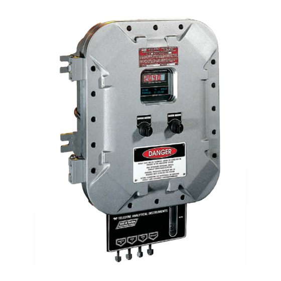
Percent Paramagnetic Oxygen Analyzer
OPERATING INSTRUCTIONS FOR
3020M
Model
Percent Paramagnetic
Oxygen Analyzer
DANGER
HIGHLY TOXIC AND OR FLAMMABLE LIQUIDS OR GASES MAY BE PRESENT IN THIS MONITORING
SYSTEM.
PERSONAL PROTECTIVE EQUIPMENT MAY BE REQUIRED WHEN SERVICING THIS SYSTEM.
HAZARDOUS VOLTAGES EXIST ON CERTAIN COMPONENTS INTERNALLY WHICH MAY PERSIST
P/N M69993
FOR A TIME EVEN AFTER THE POWER IS TURNED OFF AND DISCONNECTED.
12/18/98
ONLY AUTHORIZED PERSONNEL SHOULD CONDUCT MAINTENANCE AND/OR SERVICING. BEFORE
ECO:#98-0569
CONDUCTING ANY MAINTENANCE OR SERVICING CONSULT WITH AUTHORIZED SUPERVISOR/
MANAGER.
Teledyne Analytical Instruments
i
Advertisement
Table of Contents

Related Manuals for Teledyne 3020M


Summary of Contents for Teledyne 3020M
- Page 1 HAZARDOUS VOLTAGES EXIST ON CERTAIN COMPONENTS INTERNALLY WHICH MAY PERSIST P/N M69993 FOR A TIME EVEN AFTER THE POWER IS TURNED OFF AND DISCONNECTED. 12/18/98 ONLY AUTHORIZED PERSONNEL SHOULD CONDUCT MAINTENANCE AND/OR SERVICING. BEFORE ECO:#98-0569 CONDUCTING ANY MAINTENANCE OR SERVICING CONSULT WITH AUTHORIZED SUPERVISOR/ MANAGER. Teledyne Analytical Instruments...
-
Page 2: Model 3020M
Any safeguards required such as locks, labels, or redun- dancy, must be provided by the user or specifically requested of Teledyne at the time the order is placed. - Page 3 In addition to all standard features, this model also has separate ports for zero and span gases, and built-in control valves. The internal valves are entirely under the control of the 3020M electronics, to automatically switch between gases in synchronization with the analyzer’s operations 3020M-F: Includes flame arrestors for Group C and D service.
-
Page 4: Table Of Contents
Model 3020M Table of Contents 1 Introduction 1.1 Overview ................ 1-1 1.2 Typical Applications ............1-1 1.3 Main Features of the Analyzer ........1-1 1.4 Model Designations ............1-2 1.5 Operator Interface ............1-2 1.5.1 UP/DOWN Switch ..........1-4 1.5.2 ESCAPE/ENTER Switch ........1-4 1.5.3 Displays .............. - Page 5 4.15 The Sensor Function ............. 4-18 Maintenance 5.1 Routine Maintenance ............. 5-1 5.2 Major Internal Components ..........5-1 5.3 Sensor Replacement ............. 5-2 5.4 Fuse Replacement............5-2 5.5 System Self Diagnostic Test ........... 5-3 5.6 Output Goes Negative ............ 5-4 Teledyne Analytical Instruments...
- Page 6 Model 3020M Appendix A-1 Specifications ..............A-1 A-2 Recommended 2-Year Spare Parts List ......A-3 A-3 Drawing List ..............A-4 Teledyne Analytical Instruments...
-
Page 7: Introduction
Oxygen Analyzer is a versatile microprocessor-based instrument for detecting oxygen in a variety of gases. This manual covers the Model 3020M, percent oxygen, explosion-proof, bulkhead-mount units only. Typical Applications A few typical applications of the Model 3020M are: • Monitoring inert gas blanketing •... -
Page 8: Model Designations
Includes flame arrestors for Group B, & -C option. Operator Interface All controls and displays on the standard 3020M are accessible from outside the housing. The instrument has two simple operator controls. The operator has constant feedback from the instrument through an alphanumeric display, a digital oxygen meter, and a sample flow meter. - Page 9 4. See Figure 1-1. Through Side Port DIGITAL METER VFD SCREEN Through Side Port Through Side Port DOWN/UP CONTROL Through Side Port ESCAPE/ENTER CONTROL SCCM Figure 1-1: Model 3020M Controls, Indicators, and Connectors Teledyne Analytical Instruments...
-
Page 10: Up/Down Switch
1 Introduction Model 3020M 1.5.1 UP/DOWN Switch Functions: The UP/DOWN switch is used to select the function to be performed. Choose UP or DOWN to scroll through the following list of twelve functions: • Auto-Cal Set up an automatic calibration sequence. -
Page 11: Displays
Installation chapter of this manual. CAUTION: The power cable must be disconnected to fully remove power from the instrument. CAUTION: VOLTAGE MAY BE PRESENT ON ALARM CON- TACTS WHEN LINE POWER IS DISCONNECTED. Teledyne Analytical Instruments... - Page 12 1 Introduction Model 3020M 100-240 V 50/60Hz 3.0A Max. Figure 1-2: Electrical Connector Panel Teledyne Analytical Instruments...
-
Page 13: Gas Connector Panel
The gas connector panel, shown in Figure 1-3, contains the gas con- nections for external inlets and outlets. Those that are optional are shown shaded in the figure. The connectors are described briefly here and in detail in the Installation chapter of this manual. Teledyne Analytical Instruments... -
Page 14: Introduction
3020M electronics. Note: If you require highly accurate Auto-Cal timing, use external Auto-Cal control where possible. The internal clock in the Model 3020M is accurate to 2-3 %. Accordingly, internally scheduled calibrations can vary 2-3 % per day. Teledyne Analytical Instruments... -
Page 15: Paramagnetic Sensor
Precise Paramagnetic Sensor 2.2.1 Principles of Operation The heart of the 3020M is a paramagnetic type oxygen sensor that is maintanance free and has a long lifetime. Oxygen has a very high magnetic sucseptibility compared to other gases and thus displays a particularly para- magnetic behaviour. - Page 16 The Electronics and heating elements require a separate power source, from the rest of the 3020M capable of delivering 1.5 amps approximately at 24 volts dc. The output of the sensor is roughly calibrated to be 0 to 1 volt DC for the the range of 0 to 100 % 02.
-
Page 17: Cross Interference
Oxygen. It is actually displaying the cross sensitivity to another gas. The following table shows the cross sensitivity of some gases when changing from pure nitrogen to 100% of one of the gases listed. Teledyne Analytical Instruments... - Page 18 2 Operational Theory Model 3020M Cross Cross Sensitivity Sensitivity in vol. % in vol. % Acetylene C -0.24 Hydrogen chloride HCI -0.30 Allene C -0.44 Hydrogen fluoride HF +0.10 Ammonia NH -0.26 Hydrogen iodide HI -1.10 Argon Ar -0.22 Hydrogen sulphide H S -0.39...
-
Page 19: Sample System
Depending on the mode of operation either sample or calibration gas is delivered. The Model 3020M sample system is designed and fabricated to ensure that the oxygen concentration of the gas is not altered as it travels through the sample system. -
Page 20: Electronics And Signal Processing
This current is converted to a voltage, which is preamplified in the sensor internal electronics. The preamplified signal (0-1 Volt) is fed to the 3020M amplifier for minor processing. The digital concentration signal along with input from the control panel is processed by the microprocessor, and appropriate control signals are directed to the display, alarms and communications port. - Page 21 A to D Converter 24V Power Supply Power Supply Auto Range System Micro- Failure Processor Alarm Displays Self Test Signal Concentration D to A 0-1 V Converter Range 0-1 V Figure 2-5: Block Diagram of the Model 3020M Electronics Teledyne Analytical Instruments...
- Page 22 2 Operational Theory Model 3020M Teledyne Analytical Instruments...
-
Page 23: Installation
Immediately report any damage to the shipping agent. Mounting the Analyzer The Model 3020M is designed for bulkhead mounting in hazardous environments. There are four mounting lugs—one in each corner of the enclosure. The outline drawing, at the back of this manual, gives the mount- ing hole size and spacing. - Page 24 3 Installation Model 3020M CMSC Figure 3-1: Front View of the Model 3020M (Simplified) Teledyne Analytical Instruments...
-
Page 25: Electrical Connections
Percent Paramagnetic Oxygen Analyzer Installation 3 Figure 3-2: Required Front Door Clearance Electrical Connections Figure 3-3 shows the Model 3020M Electrical Connector Panel. There are terminal blocks for connecting power, communications, and both digital and analog concentration outputs. 100-240 V 50/60Hz 3.0A Max. -
Page 26: Primary Input Power
3 Installation Model 3020M For safe connections, ensure that no uninsulated wire extends outside of the connectors they are attached to. Stripped wire ends must insert com- pletely into terminal blocks. No uninsulated wiring should be able to come in contact with fingers, tools or clothing during normal operation. - Page 27 The signal output for concentration is linear over the currently selected analysis range. For example, if the analyzer is set on a range that was defined as 0-10 % O , then the output would be as shown in Table 3-1. Teledyne Analytical Instruments...
- Page 28 3 Installation Model 3020M Table 3-1: Analog Concentration Output—Example Voltage Signal Current Signal Output (V dc) Output (mA dc) 10.4 12.0 13.6 15.2 16.8 18.4 20.0 To provide an indication of the range, a second pair of analog output terminals are used. They generate a steady preset voltage (or current when using the current outputs) to represent a particular range.
-
Page 29: Alarm Relays
Cannot be de- feated. Actuates if self test fails. To reset a System Alarm during installation, discon- nect power to the instrument and then reconnect it. Further detail can be found in chapter 4, section 4-10. Teledyne Analytical Instruments... -
Page 30: Digital Remote Cal Inputs
(See Remote Calibration Protocol below.) Remote Calibration Protocol: To properly time the Digital Remote Cal Inputs to the Model 3020M Analyzer, the customer's controller must monitor the CAL CONTACT relay. When the contact is OPEN, the analyzer is analyzing, the Remote Cal Inputs are being polled, and a zero or span command can be sent. -
Page 31: Range Id Relays
If you have the –C Internal valve option—which includes additional zero and span gas inputs— the 3020M automatically regulates the zero, span and sample gas flow. 3.3.6 Range ID Relays There are four dedicated RANGE ID CONTACT relays. - Page 32 Toggling input. Stops/Starts any status message output from the RS-232, until st<enter> is sent again. The RS-232 protocol allows some flexibility in its implementation. Table 3-5 lists certain RS-232 values that are required by the 3020M imple- mentation. Table 3-5: Required RS-232 Options...
-
Page 33: Remote Sensor And Solenoid Valves
Installation 3 3.3.9 Remote Sensor and Solenoid Valves The 3020M is a single-chassis instrument, which has its own sensor and, in the –C option, its own gas-control solenoid valves. The REMOTE SENSOR connector is not used, and the SOLENOID RETURN connectors are used (without the –C option) to synchronize external gas control valves. -
Page 34: Gas Connections
3 Installation Model 3020M Gas Connections Figure 3-9 is an illustration of the Gas Connector Panel. Optional gas connections are shown in shaded blocks. The unit is manufactured with inch tube fittings only. Adapters must be used for metric tubing. (At least 6 mm is recommended.) For a safe connection: 1. -
Page 35: Testing The System
These valves are completely under control of the 3020M Electronics. They can be externally controlled only indirectly through the Remote Cal Inputs, described below. Pressure, flow, and safety considerations are the same as prescribed for the SAMPLE IN inlet, above. - Page 36 3 Installation Model 3020M 3-14 Teledyne Analytical Instruments...
-
Page 37: Operation
• Establish a security password, if desired, requiring Operator to log in. Before you configure your 3020M these default values are in effect: Ranges: LO = 0-5 %, MED = 0-25 %, HI = 0-100 %. Auto Ranging: ON Alarm Relays: Defeated, 10 %, HI, Not failsafe, Not latching. -
Page 38: Mode/Function Selection
The MAIN MENU consists of 12 functions you can use to customize and check the operation of the analyzer. Figure 4-1 shows the functions available with the 3020M. They are listed here with brief descriptions: 1 AUTO-CAL: Used to define and/or start an automatic calibration sequence. -
Page 39: Analysis Mode
HI or LO acting, latching or not, and failsafe or not. 9 RANGE: Used to set up three analysis ranges that can be switched automatically with auto-ranging or used as individual fixed ranges. Teledyne Analytical Instruments... -
Page 40: Data Entry
4 Operation Model 3020M 10 STANDBY: Remove power to outputs and displays, but maintain power to internal circuitry. 11 Sensor (Not Used). Any function can be selected at any time. Just scroll through the MAIN MENU with the DOWN/UP control to the appropriate function, and ENTER it. -
Page 41: The Auto-Cal Function
Note: If you require highly accurate timing of your AUTO-CAL, use external AUTO-CAL control where possible. The internal clock in the Model 3020M is accurate to 2-3 %. Accordingly, inter- nally scheduled calibrations can vary 2-3 % per day. To setup an AUTO-CAL cycle: Scroll to AUTO-CAL, and ENTER. -
Page 42: Entering The Password
4 Operation Model 3020M analyze sample gas and report on alarm conditions without entering the password. • Only one password can be defined. • After a password is assigned, the operator must log out to activate it. Until then, anyone can continue to operate the instrument without entering the new password. -
Page 43: Installing Or Changing The Password
Characters Available for Password Definition: ¥ " & < > When you have finished typing the new password, the last ENTER enters it. A verification screen appears. The screen will prompt you to retype your password for verification. Teledyne Analytical Instruments... -
Page 44: The Logout Function
4 Operation Model 3020M A A A A A Retype PWD To Verify Wait a moment for the entry (<ENT>) screen. You will be given clearance to proceed. A A A A A <ENT> TO Proceed ENTER the letters of your new password. Your password will be stored in the microprocessor and the system will immediately switch to the ANA- LYZE screen, and you now have access to all instrument functions. -
Page 45: The Self Test Function
Operation 4 The SELF-TEST Function The Model 3020M has a built-in self-testing diagnostic routine. Prepro- grammed signals are sent through the power supply, output board and sensor circuit. The return signal is analyzed, and at the end of the test the status of each function is displayed on the screen, either as OK or as a number be- tween 1 and 3. -
Page 46: Span Cal
4 Operation Model 3020M Readjust the gas pressure into the analyzer until the flowrate (as read on the analyzer’s SCCM flowmeter) settles at 700 cc/minute. If you are using password protection, you will need to enter your password to gain access to either of these functions. Follow the instructions in section 4.4 to enter your password. -
Page 47: Manual Mode Spanning
In the manual mode, the operator determines when the reading is within the acceptable range for zero. Make sure the zero gas is connected to the instrument. Teledyne Analytical Instruments 4-11... - Page 48 4 Operation Model 3020M If you have trouble zeroing, you may need to skip to section 4.8.1.3 Cell Failure. Auto Mode Zeroing Select ZERO to enter the ZERO function. The ZERO screen allows you to select whether the zero calibration is to be performed automatically or manually.
-
Page 49: The Alarms Function
4.10 The ALARMS Function The Model 3020M is equipped with 2 fully adjustable concentration alarms and a system failure alarm. Each alarm has a relay with a set of form “C" contacts rated for 3 amperes resistive load at 250 V ac. See Figure in Chapter 3, Installation and/or the Interconnection Diagram included at the back of this manual for relay terminal connections. - Page 50 4 Operation Model 3020M • One high and one low alarm, or • Both low (low and low-low) alarms. 2. Are either or both of the alarms to be configured as failsafe? In failsafe mode, the alarm relay de-energizes in an alarm condition.
-
Page 51: The Range Function
Med = 0–25 % High = 0–100%. The Model 3020M is set at the factory to default to autoranging. In this mode, the microprocessor automatically responds to concentration changes by switching ranges for optimum readout sensitivity. If the current range limits are exceeded, the instrument will automatically shift to the next higher range. -
Page 52: Setting The Analog Output Ranges
4 Operation Model 3020M The automatic air calibration range is always 0-25 % and is not pro- grammable. 4.11.1 Setting the Analog Output Ranges To set the ranges, ENTER the RANGE function mode by selecting RANGE from the MAIN MENU. The RANGE screen appears. -
Page 53: The Contrast Function
CAUTION: If you disconnect the primary power source from the analyzer, then on re-energizing, you will be required to choose to keep the configuration you previously programmed into your instrument in the Setup Mode, or it will reset to factory defaults. Teledyne Analytical Instruments 4-17... -
Page 54: The Analysis Mode
LYZE screen. ESCAPE, asserted one or more times, depending on the starting point, also switches the analyzer back to the ANALYZE screen. 4.15 Sensor Function Not Used on the 3020M. This function tests micro-fuel sensor output on the 3020 for those that are using it. 4-18... -
Page 55: Maintenance
All internal components are accessed by unbolting and swinging open the front cover, as described earlier. The major internal component locations are shown in Figure 5-1, and the fuse receptacle is shown in Figure 5-2. The 3020M contains the following major internal components: • Paramagnetic Sensor •... -
Page 56: Sensor Replacement
Should the sensor fail, contact the factory for service and replacement. Fuse Replacement The 3020M requires two 5 x 20 mm, 4 A, T type (Slow Blow) fuses. The fuses are located inside the explosion proof housing on the Electrical Connector Panel, as shown in Figure 5-2. -
Page 57: System Self Diagnostic Test
Refer to Table 5-1 for number-code information. The results screen alternates for a time with: Press Any Key To Continue... The following failure codes apply: Table 5-1: Self Test Failure Codes Power 5 V Failure 15 V Failure Both Failed Teledyne Analytical Instruments... -
Page 58: Output Goes Negative
5 Maintenance Model 3020M Analog DAC A (0–1 V Concentration) DAC B (0–1 V Range ID) Both Failed Preamp Zero too high Amplifier output doesn't match test input Both Failed Note that preamp test does not tell anything about sensor condition. If preamp is ok but instrument is not performing then sensor, sensor power supply, and sensor interconnection cable are suspects. -
Page 59: A-1 Specifications
Digital Interface: Full duplex RS-232 communications port. Power: Universal power supply 100-240 V ac, at 50 or 60 Hz, 70 Watts max. Operating Temperature: 0-45 °C Accuracy: ±2% of full scale at constant temperature. ±5% of full scale over operating temperature Teledyne Analytical Instruments... - Page 60 Appendix Model 3020M range, on factory default analysis ranges, once thermal equilibrium has been achieved. Analog outputs: 0-1 V dc percent-of-range 0-1 V dc range ID. 4-20 mADC percent-of-range 4-20 mADC range ID. Password Access: Can be user-configured for password protection.
-
Page 61: A-2 Recommended 2-Year Spare Parts List
Note: Orders for replacement parts should include the part number (if available) and the model and serial number of the instrument for which the parts are intended. Orders should be sent to: Teledyne Analytical Instruments 16830 Chestnut Street City of Industry, CA 91749-1580 Phone (626) 961-9221, Fax (626) 961-2538 TWX (910) 584-1887 TDYANYL COID or your local representative. - Page 62 Appendix Model 3020M NOTE: The MSDS on this material is available upon request through the Teledyne Environmental, Health and Safety Coordinator. Contact at (626) 934-1592 Teledyne Analytical Instruments...
- Page 63 ANALYZE. #### % Zero 1 Left=### ppm/s The zeroing process will automatically conclude when the output is within the acceptable range for a good zero. Then the analyzer automatically returns to the ANALYZE screen. Teledyne Analytical Instruments...
- Page 64 Appendix Model 3020M Manual Mode Zeroing ENTER the ZERO function. The screen that appears allows you to select between automatic or manual zero calibration. Use DOWN/UP to toggle between AUTO and MAN zero settling. Stop when MAN appears on the display.
Need help?
Do you have a question about the 3020M and is the answer not in the manual?
Questions and answers