Table of Contents
Advertisement
Quick Links
Percent Oxygen Analyzer
OPERATING INSTRUCTIONS FOR
Model 3000 PA
Percent Oxygen Analyzer
DANGER
HIGHLY TOXIC AND OR FLAMMABLE LIQUIDS OR GASES MAY BE PRESENT IN THIS
MONITORING SYSTEM.
PERSONAL PROTECTIVE EQUIPMENT MAY BE REQUIRED WHEN SERVICING THIS SYSTEM.
HAZARDOUS VOLTAGES EXIST ON CERTAIN COMPONENTS INTERNALLY WHICH MAY PER-
P/N M64573
SIST FOR A TIME EVEN AFTER THE POWER IS TURNED OFF AND DISCONNECTED.
08/06/99
ONLY AUTHORIZED PERSONNEL SHOULD CONDUCT MAINTENANCE AND/OR SERVICING.
ECO:#99-0323
BEFORE CONDUCTING ANY MAINTENANCE OR SERVICING CONSULT WITH AUTHORIZED
SUPERVISOR/MANAGER.
i
Teledyne Analytical Instruments
Advertisement
Table of Contents

Related Manuals for Teledyne 3000PA


Summary of Contents for Teledyne 3000PA
-
Page 1: Teledyne Analytical Instruments
HAZARDOUS VOLTAGES EXIST ON CERTAIN COMPONENTS INTERNALLY WHICH MAY PER- P/N M64573 SIST FOR A TIME EVEN AFTER THE POWER IS TURNED OFF AND DISCONNECTED. 08/06/99 ONLY AUTHORIZED PERSONNEL SHOULD CONDUCT MAINTENANCE AND/OR SERVICING. ECO:#99-0323 BEFORE CONDUCTING ANY MAINTENANCE OR SERVICING CONSULT WITH AUTHORIZED SUPERVISOR/MANAGER. Teledyne Analytical Instruments... - Page 2 Any safeguards required such as locks, labels, or redun- dancy, must be provided by the user or specifically requested of Teledyne at the time the order is placed.
- Page 3 In addition to all standard features, this model also has separate ports for zero and span gases, and built-in control valves. The internal valves are entirely under the control of the 3000PA electronics, to automatically switch between gases in synchronization with the analyzer’s operations...
-
Page 4: Table Of Contents
Model 3000PA Table of Contents 1 Introduction 1.1 Overview ................ 1-1 1.2 Typical Applications ............1-1 1.3 Main Features of the Analyzer ........1-1 1.4 Model Designations ............1-2 1.5 Front Panel (Operator Interface) ........1-3 1.6 Recognizing Difference Between LCD & VFD ....1-5 1.7 Rear Panel (Equipment Interface) ........ - Page 5 5.5 Major Internal Components ..........5-7 5.6 Cleaning ................ 5-8 5.7 Troubleshooting ............. 5-9 Appendix A-1 Model 3000PA Specifications ........A-1 A-2 Recommended 2-Year Spare Parts List ......A-3 A-3 Drawing List ..............A-4 A-4 19-Inch Relay Rack Panel Mount ........A-4 A-5 Application Notes on Restrictors, Pressures &...
- Page 6 Since the use of this instrument is beyond the control of Teledyne, no responsibility by Teledyne, its affiliates, and agents for damage or injury from misuse or neglect of this equipment is implied or assumed.
-
Page 7: Introduction
Model 3000PA Percent Oxygen Analyzer is a versatile microprocessor- based instrument for detecting the percentage of oxygen in a variety of background gases. This manual covers the Model 3000PA General Purpose flush-panel and/or rack-mount units only. These units are for indoor use in a nonhazardous environment. -
Page 8: Model Designations
In addition to all standard features, this model also has separate ports for zero and span gases, and built-in control valves. The internal valves are entirely under the control of the 3000PA electronics, to automatically switch between gases in synchronization with the analyzer’s operations. 3000PA-M: This model has current output signals (4-20 mA) for percent- of-range and range ID, in addition to voltage outputs. -
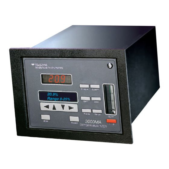
Page 9: Front Panel (Operator Interface)
Figure 1-1: Model 3000PA Front Panel Front Panel (Operator Interface) The standard 3000PA is housed in a rugged metal case with all controls and displays accessible from the front panel. See Figure 1-1. The front panel has thirteen buttons for operating the analyzer, a digital meter, an alphanu- meric display, and a window for viewing the sample flowmeter. - Page 10 1 Introduction Model 3000PA Function Keys: Six touch-sensitive membrane switches are used to change the specific function performed by the analyzer: • Analyze Perform analysis for oxygen content of a sample gas. • System Perform system-related tasks (described in detail in chapter 4, Operation.).
-
Page 11: Recognizing Difference Between Lcd & Vfd
Current signal outputs are optional and may not appear on your instrument. The connectors are described briefly here and in detail in the Installation chapter of this manual. Figure 1-2: Model 3000PA Rear Panel • Power Connection Universal AC power source. - Page 12 4-20 mA dc range ID. Note: If you require highly accurate Auto-Cal timing, use external Auto-Cal control where possible. The internal clock in the Model 3000PA is accurate to 2-3 %. Accordingly, internally scheduled calibrations can vary 2-3 % per day. Teledyne Analytical Instruments...
-
Page 13: Operational Theory
Micro-Fuel Cell: In the battery, all reactants are stored within the cell, whereas in the Micro-Fuel Cell, one of the reactants (oxygen) comes from outside the device as a constituent of the sample gas being Teledyne Analytical Instruments... -
Page 14: Anatomy Of A Micro-Fuel Cell
2 Operational Theory Model 3000PA analyzed. The Micro-Fuel Cell is therefore a hybrid between a battery and a true fuel cell. (All of the reactants are stored externally in a true fuel cell.) 2.2.2 Anatomy of a Micro-Fuel Cell The Micro-Fuel Cell is a cylinder only 1¼ inches in diameter and 1 inch thick. -
Page 15: Electrochemical Reactions
It is measured and used to determine the oxygen concentration in the gas mixture. The overall reaction for the fuel cell is the SUM of the half reactions above, or: 2Pb + O 2PbO Teledyne Analytical Instruments... -
Page 16: The Effect Of Pressure
2 Operational Theory Model 3000PA (These reactions will hold as long as no gaseous components capable of oxidizing lead—such as iodine, bromine, chlorine and fluorine—are present in the sample.) The output of the fuel cell is limited by (1) the amount of oxygen in the cell at the time and (2) the amount of stored anode material. -
Page 17: Micro-Fuel Cell "Class
Expected life in flue gas is 8 months. 2.2.6.2 Class A-5 Cell The class A-5 cell is for use in applications where it is exposed intermit- tently to carbon dioxide concentrations up to 100 % in the sample gas. Teledyne Analytical Instruments... -
Page 18: Sample System
2 Operational Theory Model 3000PA Nominal output in air is 0.19 mA, and 90 % response time is 45 s. Expected life in flue gas is 8 months. 2.2.6.3 Class B-1 Cell The class B-1 cell is for use in applications where it is exposed to less than 0.1 % of carbon dioxide, and where fast response is important. - Page 19 Sample In port by teeing to the port with appropriate valves. The shaded portion of the diagram shows the components added when the –C option is ordered. The valving is installed inside the 3000PA-C enclosure and is regulated by the instrument's internal electronics.
-
Page 20: Electronics And Signal Processing
2 Operational Theory Model 3000PA Span In Components in the shaded area are in the -C option (internal control valves) only and are not shown in the piping diagram above. Zero In Sample In Cell Solenoid Valves In vacuum service the... - Page 21 The preamplifier board is mounted on top of the motherboard as shown in the figure. These boards are accessible after re- moving the back panel. Figure 2-7 is a block diagram of the Analyzer electronics. Figure 2-7: Block Diagram of the Model 3000P Electronics Teledyne Analytical Instruments...
- Page 22 2 Operational Theory Model 3000PA In the presence of oxygen the cell generates a current. A current to voltage amplifier converts this current to a voltage, and then the voltage is amplified in the second stage amplifier. The second stage amplifier also supplies temperature compensation for the oxygen sensor output.
-
Page 23: Installation
Immediately report any damage to the shipping agent. Mounting the Analyzer The Model 3000PA is for indoor use in a general purpose area. It is NOT for use in hazardous environments of any type. The standard model is designed for flush panel mounting. Figure 3-1 is an illustration of the 3000PA standard front panel and mounting bezel. -
Page 24: Rear Panel Connections
Figure 3-2: Required Front Door Clearance Rear Panel Connections Figure 3-3 shows the Model 3000PA rear panel. It contains all of the gas and electrical inputs and outputs. Some ports are optional equipment. Refer to page iii in the front of this manual for options included in your instrument. -
Page 25: Gas Connections
Percent Oxygen Analyzer Installation 3 Figure 3-3: Rear Panel of the Model 3000PA 3.3.1 Gas Connections Before using this instrument, it should be determined if the unit will be used for pressurized service or vacuum service and low pressure applica- tions. -
Page 26: Electrical Connections
3 Installation Model 3000PA The unit is manufactured with inch tube fittings. Six millimeter adapters are supplied for metric system installations. For a safe connection: 1. Insert the tube into the tube fitting, and finger-tighten the nut until the tubing cannot be rotated freely, by hand, in the fitting. (This may require an additional turn beyond finger-tight.) - Page 27 20 mA at full scale. (Full scale = 100% of programmable range.) 4-20 mA dc Range ID: –M option only. 8 mA = Low Range, 12 mA = Medium Range, 16 mA = High Range, 20 mA = Air Cal Range. Teledyne Analytical Instruments...
- Page 28 3 Installation Model 3000PA Figure 3-4: Analog Output Connections Alarm Relays: The three alarm-circuit connectors are spring terminals for making connections to internal alarm relay contacts. Each provides a set of Form C contacts for each type of alarm. Each has both normally open and normally closed contact connections.
- Page 29 (See Remote Calibration Protocol below.) Remote Calibration Protocol: To properly time the Digital Remote Cal Inputs to the Model 3000PA Analyzer, the customer's controller must monitor the Cal Relay Contact. When the contact is OPEN, the analyzer is analyzing, the Remote Cal Inputs are being polled, and a zero or span command can be sent.
- Page 30 3 Installation Model 3000PA Note: The Remote Probe connector (paragraph 3.3.3) provides signals to ensure that the zero and span gas valves will be controlled synchronously. If you have the –C Internal valve option—which includes additional zero and span gas inputs—...
-
Page 31: Remote Probe Connector
Toggling input. Stops/Starts any status message output from the RS-232, until st<enter> is sent again. The RS-232 protocol allows some flexibility in its implementation. Table 3-2 lists certain RS-232 values that are required by the 3000PA implementation. Table 3-2: Required RS-232 Options... -
Page 32: Installing The Micro-Fuel Cell
3 Installation Model 3000PA Figure 3-7: FET Series Resistance Installing the Micro-Fuel Cell The Micro-Fuel Cell is not installed in the cell block when the instrument is shipped. It must be installed before the analyzer is placed in service. Once it is expended, or if the cell is exposed to air for too long, the Micro-Fuel Cell will need to be replaced. -
Page 33: Operation
• Set alarm setpoints, and modes of alarm operation (latching, failsafe, etc). Before you configure your 3000PA these default values are in effect: Ranges: LO = 1 %, MED = 5 %, HI = 10 % Auto Ranging: ON Alarm Relays: Defeated, 10 %, HI, Not failsafe, Not latching Zero: Auto, every 0 days at 0 hours Span: Auto, at 20.9 %, every 0 days at 0 hours... -
Page 34: Using The Data Entry And Function Buttons
4 Operation Model 3000PA Using the Data Entry and Function Buttons Data Entry Buttons: The < > arrow buttons select options from the menu currently displayed on the VFD screen. The selected option blinks. When the selected option includes a modifiable item, the arrow buttons can be used to increment or decrement that modifiable item. -
Page 35: The System Function
Installing or Changing a Password, below, for a table of ASCII characters available.) Once a unique password is assigned and activated, the operator MUST enter the UNIQUE password to gain access to set-up functions which alter the instrument's Teledyne Analytical Instruments... -
Page 36: Setting The Display
4 Operation Model 3000PA operation, such as setting the instrument span or zero setting, adjusting the alarm setpoints, or defining analysis ranges. After a password is assigned, the operator must log out to activate it. Until then, anyone can continue to operate the instrument without entering the new password. -
Page 37: Setting Up An Auto-Cal
Note: If you require highly accurate Auto-Cal timing, use external Auto-Cal control where possible. The internal clock in the Model 3000PA is accurate to 2-3 %. Accordingly, internally scheduled calibrations can vary 2-3 % per day. To setup an Auto–Cal cycle: Choose System from the Function buttons. -
Page 38: Entering The Password
4 Operation Model 3000PA If you have decided not to employ password security, use the default password TBEAI. This password will be displayed automatically by the microprocessor. The operator just presses the Enter key to be allowed total access to the instrument’s features. -
Page 39: Installing Or Changing The Password
Characters Available for Password Definition: ¥ " & < > When you have finished typing the new password, press Enter . A verification screen appears. The screen will prompt you to retype your password for verification. Teledyne Analytical Instruments... -
Page 40: Logout
4 Operation Model 3000PA A A A A A Retype PWD To Verify Wait a moment for the entry screen. You will be given clearance to proceed. A A A A A <ENT> TO Proceed Use the arrow keys to retype your password and press Enter when finished. -
Page 41: System Self-Diagnostic Test
Operation 4 4.3.5 System Self-Diagnostic Test The Model 3000PA has a built-in self-diagnostic testing routine. Pre- programmed signals are sent through the power supply, output board and sensor circuit. The return signal is analyzed, and at the end of the test the status of each function is displayed on the screen, either as OK or as a number between 1 and 3. -
Page 42: Cell Failure
Zero or Span function. 4.4.1. Cell Failure When the sensor in the 3000PA begins to fail, the analyzer will usually require more and more frequent calibration. If the 3000PA analysis readings drift downward uncharacteristically, try recalibration. If recalibration raises the readings temporarily, the cell may be failing. -
Page 43: Span Cal
Percent Oxygen Analyzer Operation 4 Although the B-1 cell is standard in the 3000PA, check Specific Model Information in the Front Matter in this manual for the class of cell you purchased. Then check Cell Replacement in chapter 5 Maintenance, and do the prescribed calculations. -
Page 44: Manual Mode Spanning
The instrument then automatically enters the Analyze func- tion. The Alarms Function The Model 3000PA is equipped with 2 fully adjustable concentration alarms and a system failure alarm. Each alarm has a relay with a set of form 4-12... - Page 45 4. Are either of the alarms to be defeated? The defeat alarm mode is incorporated into the alarm circuit so that maintenance can be performed under conditions which would normally activate the alarms. 4-13 Teledyne Analytical Instruments...
- Page 46 4 Operation Model 3000PA The defeat function can also be used to reset a latched alarm. (See procedures, below.) If you are using password protection, you will need to enter your password to access the alarm functions. Follow the instructions in section 4.3.3 to enter your password.
-
Page 47: The Range Function
Med = 0–5.00 % High = 0–10.00 %. The Model 3000PA is set at the factory to default to autoranging. In this mode, the microprocessor automatically responds to concentration changes by switching ranges for optimum readout sensitivity. If the current range limits are exceeded, the instrument will automatically shift to the next higher range. -
Page 48: Autoranging Analysis
4 Operation Model 3000PA 4.6.2 Autoranging Analysis Set your analysis ranges as in 4.6.1, above. Leave Mode in Auto, or use the arrow buttons to change back to Auto. When operating in autoranging, if the oxygen concentration in your sample goes ABOVE your HIGHEST range setting, the analyzer will go into the special 25 % cal range. -
Page 49: The Analyze Function
Signal Output The standard Model 3000PA Percent Oxygen Analyzer is equipped with two 0–1 V dc analog output terminals accessible on the back panel (one concentration and one range ID). The –MA option also has two isolated 4–... - Page 50 4 Operation Model 3000PA The analog output signal has a voltage which depends on the oxygen concentration AND the currently activated analysis range. To relate the signal output to the actual concentration, it is necessary to know what range the instrument is currently on, especially when the analyzer is in the autoranging mode.
-
Page 51: Maintenance
To have a replacement cell available when it is needed, TAI recom- mends that one spare cell be purchased 4-5 months after commissioning the 3000PA, or shortly before the end of the cell warranty period. CAUTION: Do not stockpile cells. The warranty period starts on the day of shipment. -
Page 52: When To Replace A Cell
Cell Output: ### µA The “good” cell output range depends on the class of cell your ana- lyzer is using. The B-1 cell is standard in the 3000PA, but others can be specified. Check Specific Model Information in the Front Matter in this manual for the class of cell you purchased. -
Page 53: Removing The Micro-Fuel Cell
5. When it is free, unscrew the Cap from the nylon Probe. Hold the Probe vertically to prevent dropping the cell out of the probe. 6. Remove the Cell from the Probe, and dispose of it in an environmentally safe manner. Teledyne Analytical Instruments... - Page 54 5 Maintenance Model 3000P Figure 5-1: Removing or Installing a Micro-Fuel Cell Teledyne Analytical Instruments...
-
Page 55: Installing A New Micro-Fuel Cell
5.2.5 Cell Warranty The Class B-1 Micro-Fuel cell is standard in the Model 3000PA. This cell is warranted for 6 months from the date of shipment. Check the Spe- cific Model Information, and note any Addendum that might be attached to the front of this manual for special information applying to the Cell in your instrument. -
Page 56: Fuse Replacement
1. Press the System button to enter the system mode. 2. Use the < > arrow keys to move to More, and press Enter . 3. Use the < > arrow keys to move to Self-Test, and press Enter . The following failure codes apply: Teledyne Analytical Instruments... -
Page 57: Major Internal Components
The gas piping is illustrated in Figure 2-4, and the major electronic components locations are shown in Figure 2-5, in chapter 2. WARNINGS: See warnings on the title page of this manual. The 3000PA contains the following major components: • Analysis Section Micro Fuel Cell (B-1 standard—others available) -
Page 58: Cleaning
Do not use any harsh solvents such as paint thinner or benzene. For panel-mounted instruments, clean the front panel as prescribed in the above paragraph. DO NOT wipe front panel while the instrument is controlling your process. Teledyne Analytical Instruments... -
Page 59: Troubleshooting
Turn the analyzer off, then back on again. Press the System key when prompted by the analyzer "Press System for default Values". This will return the analyzer to its default settings in calibration and zero values. Now proceed to carefully calibrate and zero the analyzer. Teledyne Analytical Instruments... - Page 60 5 Maintenance Model 3000P 5-10 Teledyne Analytical Instruments...
-
Page 61: Appendix
Percent Oxygen Analyzer Appendix Appendix A-1 Model 3000PA Specifications Packaging: General Purpose • Flush panel mount (Standard). • Rack mount — Relay rack mounted to contain either one or two instruments in one 19" relay rack mountable plate (Optional). Sensor: Class B-1 Micro-Fuel Cell (standard). Others available. - Page 62 Appendix Model 3000PA Accuracy: ±2% of full scale at constant temperature. ±5% of full scale over operating temperature range, on factory default analysis ranges, once thermal equilibrium has been reached. Analog outputs: 0-1 V dc percent-of-range (Standard) 0-1 V dc range ID (Standard) 4-20 mA dc—isolated—...
-
Page 63: Recommended 2-Year Spare Parts List
NOTE: Orders for replacement parts should include the part number (if available) and the model and serial number of the instrument for which the parts are intended. Orders should be sent to: TELEDYNE Analytical Instruments 16830 Chestnut Street City of Industry, CA 91749-1580 Phone (626) 934-1500, Fax (626) 961-2538... -
Page 64: Drawing List
Appendix Model 3000PA A-3 Drawing List D-64573 Final Assembly/Outline Drawing A-4 19-inch Relay Rack Panel Mount Figure A-1: Single and Dual 19" Rack Mounts Teledyne Analytical Instruments... - Page 65 The second function that the restriction device provides is a pressure drop. This device is selected to provide the only significant pressure drop in the sample path. Teledyne Analytical Instruments...
- Page 66 ( off scale of flow-meter), pressure drops other than the restriction device could become significant , and result in pressurizing the cell. Example 2, A 3000PA is configured for vacuum service as follows. The un-marked restrictor is placed in the sample vent port. The down stream end of the restrictor is then connected to a vacuum pump and by-pass valve.
- Page 67 Operation without a restrictor device is not recommend as mentioned above. A 3000PA without any flow restrictor device was tested on 11-19-97. This results in a flow rate of 2.4 SLPM @ 1 PSIG. This is a cv of 0.023 for the standard sample sys.
-
Page 68: Auto Mode Zeroing
Appendix Model 3000PA Zero Cal The Zero button on the front panel is used to enter the zero calibration function. Zero calibration can be performed in either the automatic or manual mode. In the automatic mode, an internal algorithm compares consecutive readings from the sensor to determine when the output is within the accept- able range for zero. - Page 69 Once span settling completes, the information is stored in the microprocessor, and the instrument automatically returns to the Analyze mode. NOTE: The MSDS on this material is available upon request through the Teledyne Environmental, Health and Safety Coordinator. Contact at (626) 934-1592 Teledyne Analytical Instruments...
Need help?
Do you have a question about the 3000PA and is the answer not in the manual?
Questions and answers