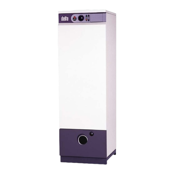
Summary of Contents for ACV Delta 25
- Page 1 delta delta performance performance Combination boiler 25 / 35 / 45 / 55 F25 / F35 / F45 / F55 G25 / G35 / G45 / G55 Installation, Operating and Servicing Instructions excellence in hot water 11/06/2004 - 66400000...
-
Page 2: Table Of Contents
ACV cannot accept liability for any damage resulting from incorrect installation or from the use of components or fittings not specified by ACV. Any failure to follow instructions relating to tests and test procedures may result in personal injury or risks of pollution. -
Page 3: Installation
6. Expansion tank Chimney height 7. Room thermostat (fig. 2) Chimney diameter 8. ACV 13 controller (see controller kit on page 5) (fig. 3) 9. Central heating isolation valve 10. Discharge outlet Fig. 1: Boiler room ventilation and chimney connection... - Page 4 4.5 bar must be fitted. 2.2.3.2 Safety unit The tank safety unit must be ACV approved and calibrated to 7 bar. The valve discharge must be connected to the waste water system in accordance with current regulations.
-
Page 5: Oil Supply
INSTALLATION 2.2.4 CONTROLLER KITS KIT 1: ACV 13.00 / Basic Basic kit for regulating initial flow temperature according to weather conditions. It comprises: a temperature regulator with analogue clock, wall-mounted water temperature sensor (-30/130° C), external sensor (-30/50° C), 3-pin servomotor SQY 31 230 V and an Fig. -
Page 6: Electrical Connections
INSTALLATION ELECTRICAL CONNECTION It is important to switch the boiler off before carrying out 2.4.1 DESCRIPTION OF POWER SUPPLY any work. The boiler operates on single phase 230 V – 50 Hz. An on-off switch box with 6 A fuses must be fitted outside the boiler to allow power to be shut off during servicing and before any repairs are carried out on the boiler. -
Page 7: Starting Up
RECOMMENDATION HOT WATER CIRCUITS ACV recommend that boilers should be serviced at least once a year. The burner must be serviced and tested by a competent engineer. 1. Fill the domestic hot water circuit and bring it up to pressure. -
Page 8: Servicing The Burner
6. After emptying, return the valves to their initial positions. To allow the tank to be emptied, valve (C) must be situated at ground level. Fig. 13b: Emptying the hot water circuit SPARE PARTS Please refer to the specific document available from ACV or your distributor.


