Table of Contents
Advertisement
Quick Links
OPERATING INSTRUCTIONS FOR
Model 3500 Series
Laser Gas Analysis System
P/N MXXXX
ECO:
DANGER
Toxic gases and or flammable liquids may be present in this monitoring system.
Personal protective equipment may be required when servicing this instrument.
Hazardous voltages exist on certain components internally which may persist
for a time even after the power is turned off and disconnected.
Only authorized personnel should conduct maintenance and/or servicing.
Before conducting any maintenance or servicing, consult with authorized
supervisor/manager.
Copyright © 2005 Teledyne Analytical Instruments
Teledyne Analytical Instruments
Advertisement
Table of Contents

Subscribe to Our Youtube Channel
Related Manuals for Teledyne 3500 Series


Summary of Contents for Teledyne 3500 Series
- Page 1 Hazardous voltages exist on certain components internally which may persist for a time even after the power is turned off and disconnected. Only authorized personnel should conduct maintenance and/or servicing. Before conducting any maintenance or servicing, consult with authorized supervisor/manager. Copyright © 2005 Teledyne Analytical Instruments Teledyne Analytical Instruments...
- Page 2 Any safeguards required such as locks, labels, or redundancy, must be provided by the user or specifically requested of Teledyne at the time the order is placed.
- Page 3 Laser Gas Analyzer Specific Model Information Instrument Serial Number: _______________________ Instrument Range: _______________ Calibrated for: _______________ Background Gas: _______________ Zero Gas: _______________ Span Gas: _______________ Teledyne Analytical Instruments...
- Page 4 NOTE: Additional information and comments regarding a specific component or procedure are highlighted in the form Symbol of a note. CAUTION: THE ANALYZER SHOULD ONLY BE USED FOR THE PURPOSE AND IN THE MANNER DESCRIBED IN THIS MANUAL. Teledyne Analytical Instruments...
- Page 5 Manuals do get lost. Additional manuals can be obtained from Teledyne at the address given in the Appendix. Some of our manuals are available in electronic form via the internet. Please visit our website at: www.teledyne-ai.com.
-
Page 6: Table Of Contents
Table of Contents Peter.Adam@linde-gas.com List of Figures ................ix List of Tables ................xi Introduction ................... 1 1.1 Overview 1.2 Models Available in the 3500 Series 1.2.1 Available Options 1.2 Classification of LGA-2000 Laser Gas Analysis Systems 1.2 Typical Applications 1.3 Features... - Page 7 4.3.4.3 Backup 4.3.4.4 Restore 4.3.5 Com 4.3.6 Alarm 4.3.7 Additional Menus 4.3.7.1 Message Code: 4.3.7.2 Password Input: 4.3.7.3 Error Protection Menu: Alarm Messages ................61 5.1 Relay Alarm 5.2 4-20mA Analog Output 5.3 LCD Alarm Message Display Teledyne Analytical Instruments...
- Page 8 6.1.1 Adjusting the Purge Gas Flow 6.1.2 Clean the Optical Parts 6.1.3 Optimize the Optical Transmission Alignment 6.2. Calibration 6.2.1 Calibration Procedure 6.2.2 Calibration Software Extended Communication Functions ........75 Appendix..................77 Specifications Recommended Spare Parts List Reference Drawings Index..................... 81 Teledyne Analytical Instruments viii...
-
Page 9: List Of Figures
Figure 1-2: Model 2500 Laser Gas Analysis System....... 6 Figure 2-1: System Diagram for the Model 3500 Series Analyzers . 7 Figure 2.2 Schematic of “Single line” Spectroscopy......9 Figure 3-1: General Layout of the Model 3500 Series Analyzer ..12 Figure 3.2: Allowed offset for welded flanges ........ - Page 10 Figure 4.35 Time sequence of the alarm relay automatic restoration ................56 Figure 6.1 Schematic of the calibration setup ....... 70 Figure 6.2 Removing the Transmitter Receiver Units....72 Figure 7.1 Schematic for Networked Multiple-point Remote Measurement on Model 3500 Systems........75 Teledyne Analytical Instruments...
-
Page 11: List Of Tables
Table 1-2: Typical Gas Analysis and Range........3 Table 3.1 Electric connections & definitions of Input, Output Signals of Central Processing Unit ......... 21 Table 5.1 Relays and output status for Various Operation Modes 62 Table 5.2: LCD Display Alarm Messages ........63 Teledyne Analytical Instruments... - Page 12 Since the use of this instrument is beyond the control of Teledyne, no responsibility by Teledyne, its affiliates, and agents for damage or injury from misuse or neglect of this equipment is implied or assumed.
- Page 13 WARNING: THE WAVELENGTH OF THE LASER BEAM INSIDE THE MODEL 3500 SERIES OF ANALYZERS IS IN THE RANGE OF 0.7 ~ 2µM. IT IS INFRARED AND INVISIBLE. DO NOT LOOK DIRECTLY OR WITH OPTICAL INSTRUMENT AT THE DIRECTION OF THE...
- Page 14 Model 3500 Teledyne Analytical Instruments...
-
Page 15: Introduction
Introduction Introduction 1.1 Overview The Model 3500 series Laser Gas Analysis System comprises a range of instruments based on the features and configuration chosen at the time of purchase. The system uses laser spectroscopy to accurately measure and monitor the composition of a single or multiple gas species in a gas mixture. -
Page 16: Classification Of Lga-2000 Laser Gas Analysis Systems
The instruments in the Model 3500 range are named according to the following rule: Model 3500: Single gas analyzer Model 3500-2: Two gas analyzer Suffix C: Standard configuration without optical fiber Suffix F Standard configuration with optical fiber Suffix I: Intrinsically safe Suffix P: Explosion-proof Teledyne Analytical Instruments... -
Page 17: Typical Applications
0.1 ppm 0-15 ppm, 0-8000 ppm 0.02 ppm 0-5 ppm, 0-1000 ppm 0.2 ppm 0-20 ppm, 0-10000 ppm 200 ppm 0-8000 ppm, 0-100% Vol. 0.05 ppm 0-10 ppm, 0- 70% Vol. 5 ppm 0-1000 ppm, 0-30% Vol. Teledyne Analytical Instruments... -
Page 18: Features
• No replacement parts • No cross interference from background gas species • Enhanced accuracy over conventional IR and photonic measurement systems 1.4 System Components The Model 3500 consists of: • Control unit • Analysis section • Purging system Teledyne Analytical Instruments... -
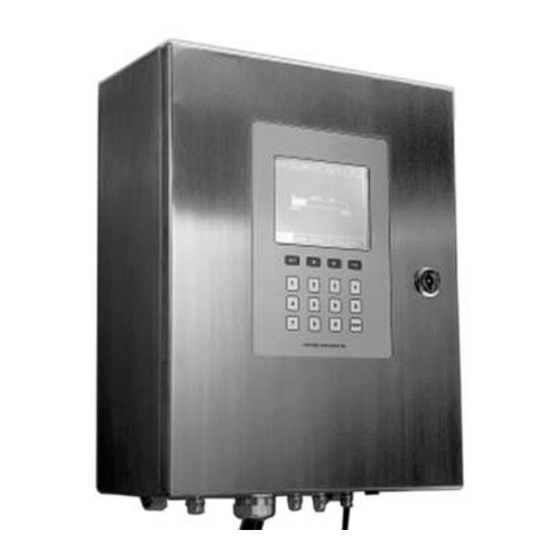
Page 19: Figure 1-1 Control Section
Figure 1-1 Control Section The system is equipped with a separate power supply and output control section which is also mounted remotely from the measurement site. It houses power supplies and connectors for signal and relay output. See Figure 1-2. Teledyne Analytical Instruments... -
Page 20: Figure 1-2: Model 2500 Laser Gas Analysis System
Figure 1-2 shows a typical Model 3500 Laser Gas Analysis System with the control section remotely located from the analysis portion. Figure 1-2: Model 2500 Laser Gas Analysis System Teledyne Analytical Instruments... -
Page 21: Operational Theory
LCD screen. Signal and relay output is taken from the power supply/control box. See Figure 2-1. Figure 2-1: System Diagram for the Model 3500 Series Analyzers Teledyne Analytical Instruments... -
Page 22: Principles Of Operation
This feature, no interference from background dust and gases, enables the laser gas analysis systems to be applied on the spot for online gas analysis. Conventional infrared spectroscopy, due Teledyne Analytical Instruments... -
Page 23: Figure 2.2 Schematic Of "Single Line" Spectroscopy
Figure 2.2 Schematic of “Single line” Spectroscopy. The Model 3500 series of analyzers do not need complex gas sampling and pretreatment. They have extremely quick response because they skip the long gas sampling and transport process. As a... -
Page 24: Software
In addition, the software establishes data communication with PC through the RS232 serial communication port and GPRS modules. TAI provides WINDOWS-based PC service program for all models in the 3500 series. Please refer to Appendix A for details. Teledyne Analytical Instruments... -
Page 25: Installation
3.2.1 Installation and Adjustment Tools The following tools will be required for proper installation: Wrenches M5 wrench—used to tighten the M5 bolts connecting the instrument flange and transmitter/receiver. Two 12” adjustable wrenches—used to tighten EMC and nut connector. Teledyne Analytical Instruments... -
Page 26: Figure 3-1: General Layout Of The Model 3500 Series Analyzer
3mm slotted screwdriver—used to connect electric parts and components. Digital multimeter. Tubing cutter. Tube bender for 6 and 12 mm tubing Figure 3-1: General Layout of the Model 3500 Series Analyzer Teledyne Analytical Instruments... -
Page 27: Choosing Installation Spot
The precision adjustment between the welding flange and the instrument flange with the supplied O-ring can fine tune the optical transmission to a limited extent. This allows for the two welding flanges Teledyne Analytical Instruments... -
Page 28: Installing Instrument Flanges
Raise the instrument flanges to the same height as the welded flanges, then tighten the 8 M16 bolts to about half tight to make sure that the O- rings are sealing. Typically the distance between the instrument flange and the welding flange is around 3mm. See Figure 3.3. Teledyne Analytical Instruments... -
Page 29: Checking Offset Using The Laser Pen And Target
1. Mount the laser pen on one instrument flange and the scaled target onto the other instrument flange. Tighten with mounting nuts. 2. Turn on the laser pen and observe the light spot on the target. Teledyne Analytical Instruments... -
Page 30: Adjusting The Coaxial Offset Of The Instrument Flanges
6. Keep the laser pen on, tighten the 4 fastening screws on the instrument flange where the laser pen is mounted, and keep an eye on the light spot on the scaled target. If it moves, repeat steps 1, 2, and 3 until the light spot does not move. Teledyne Analytical Instruments... -
Page 31: Installing The Transmitter Unit And The Receiver Unit
Figure 3.5 Dimension of the Central Processing Unit (in mm). To avoid turning on the power supply inadvertently and possibly causing harm to operators in the field, the central processing unit is Teledyne Analytical Instruments... -
Page 32: Purge System Installation
Connect the inlet to a suitable purge gas supply. A regulator should be used to control the pressure to the purge system. The gas pressure depends on the particular purge system installed and will be noted on the unit. Teledyne Analytical Instruments... -
Page 33: Electric Wiring And Connection
Non-fiber optic models (C option) use diode lasers without a fiber pigtail. In these models, the laser diode is located in the transmitter unit. The fiber optic models (F option) use a fiber pigtail to transmit the laser Teledyne Analytical Instruments... -
Page 34: Figure 3.7 Electric Connection Ports On The Central Processing Unit For Non-Fiber Optic Analysis Systems
3. Cable port between the central processing unit and the probe 4. 4-20mA connection port 5. Relay connection port 6. Fuse socket 7. Power supply port Figure 3.7 Electric Connection Ports on the Central Processing Unit for Non-fiber Optic Analysis Systems. Teledyne Analytical Instruments... -
Page 35: Figure 3.8: Electric Connection Ports On The Central Processing Unit For Analysis Systems Using Fiber Optic Pigtail
4-20mA Concentration Output (-) 4-20mA Concentration Output (+) 4-20mA Pressure Input (-) 4-20mA Pressure Input (+) 4-20mA Pressure Input24V Power Supply 4-20mA Temperature Input (-) 4-20mA Temperature Input (+) 4-20mA Temperature Input 24V Power Supply Warning Alarm Relay 1 Teledyne Analytical Instruments... -
Page 36: Optimize Of The Optical Transmission Alignment
(see Figure 3.3). Adjust the flange by either tightening or loosening the 4 M16 bolts until the measured voltage stabilizes to its maximum value. Tighten the four fastening screws. d. Replace the box cover. Teledyne Analytical Instruments... -
Page 37: Operation
The front panel is showed in Figure 4.1. Figure 4-1: Model 3500 Series Front Panel Teledyne Analytical Instruments... -
Page 38: System Mode
In this mode, the system initializes and performs the self-test routine. The first menu on LCD screen is the start-up menu and shows the company logo and name, instrument model and name. See Figure 4.2. Teledyne Analytical Instruments... -
Page 39: Figure 4.2 System Start-Up Screen
After initialization, the system starts the self test routine to examine whether the system function modules are working properly. Normally, the process takes about 6 minutes. Figure 4.4 is the system self test screen showing “System Selftesting…” status. If everything is OK, Teledyne Analytical Instruments... -
Page 40: Normal Mode
MainMenu in graphics mode). The system computes the gas concentration value using default values for input parameters and sends out 4-20mA output CAUTION: SCREEN DISPLAY OF THE MEASURED CONCENTRATION MAY BE HIGHLY INACCURATE IN THIS MODE. Teledyne Analytical Instruments... -
Page 41: Error Mode
There are six main menus: • MainMenu • Display • System • Cali. • Com. • Alarm The entire menu has a simple and clear structure as shown in Figure 4.5 and is easy to operate. Teledyne Analytical Instruments... -
Page 42: Mainmenu
MainMenu is the menu displayed after the system finishes start-up, initializing and selftesting, and enters normal working status. The MainMenu has two display modes—graphics, and numeric. The two modes are switched through the Display menu. The graphics mode is shown in Figure 4.6. Teledyne Analytical Instruments... -
Page 43: Figure 4-6: Mainmenu—Graphic
Units for gas concentration h. Upper limit of gas concentration alarm range. The lower limit is shown on the left side. These two values can be reset from the Alarm menu. The numerical value mode is shown in Figure 4.7. Teledyne Analytical Instruments... -
Page 44: Figure 4.7 Numerical Value Mode Of The Mainmenu
• Con. output--4mA: gas concentration value corresponding to 4mA of the 4-20mA gas concentration output. Teledyne Analytical Instruments... - Page 45 π τ τ set measurement. Typically, the Model 3500 series instruments have at ∼1 second at the factory. However, it can also be set at any value in the range of 0.1~1 second upon customer request to suit particular applications that require faster response time. Contact technical support for more information.
- Page 46 By operating the above keystrokes, you can enter the submenu of the MainMenu : • Display : Press “SET”—the system enters the Display menu. • System : Press “SET”—the system asks for Sys Pwd. If the password is correct, the system enters the System menu. Teledyne Analytical Instruments...
-
Page 47: Display
Figure 4.8 Display menu • Mode : Press “SET”, a small window popes up, asking the user to choose between Numerical Value Mode and Graphics Mode. The difference between the two display modes is described in Section 4.3.1 MainMenu . Teledyne Analytical Instruments... -
Page 48: Figure 4.9 Display Mode Options
Operation Model 3500 Figure 4.9 Display Mode Options • Unit : Choose unit for different parameters. Press “SET” to enter Unit submenu. Figure 4.10 Unit Menu Teledyne Analytical Instruments... -
Page 49: Figure 4.11 Set Con. Unit Menu
The units g/Nm and mg/Nm are mass volume ratio concentration units (standard state , pressure: 1.01325Bar, temperature: 273.1K). Teledyne Analytical Instruments... -
Page 50: Model
• Language : Press “SET” to select between Chinese and English. Figure 4.12 Pop-up Window for Language Selection After the selection, all menus are in the language selected. • TimeDate : Press “SET” to set system clock time and date. Figure 4.13 TimeDate Menu Teledyne Analytical Instruments... -
Page 51: Figure 4.14 Admin. Menu
To change the passwords of System and Cali. , you must enter the Admin. Menu. The user who has the Admin. password has the highest authority. With this privilege you can reset System pwd and Cali. pwd to ensure authorized system management. Teledyne Analytical Instruments... -
Page 52: System
The system main menu is shown in Figure 4.15. The data fields for this menu are as follows: • Path length: optical path length of the gas under test. • Gas temperature: temperature of the gas under test. • Gas pressure: pressure of the gas under test. Teledyne Analytical Instruments... -
Page 53: System Parameter Input Method
None will be shown here if it can only be keyed in. 4.3.3.1 S YSTEM ARAMETER NPUT ETHOD As an example, the following demonstrates the way to reset optical path length. 1. Move the cursor to “Length” button and press “SET”. The Path length input window pops up. Teledyne Analytical Instruments... -
Page 54: Figure 4.16 Set Optical Path Length
Figure 4.16 Set Optical Path Length 2. Key in the new optical path length value (Figure 4.17). Figure 4.17 Input the New Optical Path Length Value 3. Press “SET” to accept the new setting. The call-outs on Figure 4.17 refer to: Teledyne Analytical Instruments... -
Page 55: System Sub Menus
• Av Times: —set number of times used to calculate average concentration (0-90), manual. • Out Set: —set the range of 4-20mA concentration output. • Purge: —set parameters of the purging gas including purging gas concentration, purging path and purging gas temperature. Teledyne Analytical Instruments... - Page 56 The buttons on this menu refer to: 4mA: Set the corresponding gas temperature when the temperature input signal is 4mA. 20mA: Set the corresponding gas temperature when the temperature input signal is 20mA. 2. Measured Pressure Menu Teledyne Analytical Instruments...
- Page 57 3. Concentration Output Menu Items displayed on the Concentration Output screen (Figure 4.20) are: • Con. output--4mA: The measured gas concentration output is in the form of 4-20mA. Con. output--4mA is the gas concentration value corresponding to 4mA. Teledyne Analytical Instruments...
- Page 58 On the Purge Parameter Menu (Figure 4.21), the selections are: • Pur Len: Set the purging path length (Lf2+Lf1+Lb1+Lb2, Figure 4.22). • Pur. Temp: Set the purging gas temperature. • Pur. Con.: Set the concentration of gas under test in the purging gas. Teledyne Analytical Instruments...
-
Page 59: Figure 4.22 Schematic Showing Purging Gas Channel
Laser Gas Analyzer Operation Figure 4.21 Purge Parameter Menu Figure 4.22 Schematic showing purging gas channel Note: The residual gas in LF3 and LB3 has been interpreted during zeroing, and thus has no influence on the Teledyne Analytical Instruments... -
Page 60: Cali
• Calibrate coefficient: Fill the calibration tube with standard gas (such as high purity Nitrogen) with known concentration of the gas under test, and perform a span calibration operation. Note: Perform the zero calibration before doing the span calibration. Teledyne Analytical Instruments... -
Page 61: Adjust Zero
Zero : Press “SET” when the cursor is on “Zero” button, the system enters the Pre zeroing menu (Figure 4.24). Figure 4.24 Pre zeroing sub menu Choose “Accept” to accept the parameters, and the system starts zeroing (Figure 4.25). The zeroing gauge bar shows the progress of the process. Teledyne Analytical Instruments... -
Page 62: Cali. Co
Figure 4.25 Zeroing menu 4.3.4.2 C Figure 4.26 is the Cali.Co sub menu. On this menu, operators can set calibration optical path length, temperature, pressure, concentration parameters needed by the calibration system. Figure 4.26 Calibration coefficient sub menu Teledyne Analytical Instruments... - Page 63 • Pre.Cali: After inputting all the parameters above, press Pre.Cali button to accept them, and the system enters the Calibration Confirmation menu (Figure 4.27). Note: The system accepts the above input parameters only after Pre.Cali is pressed. Figure 4.27 Calibration confirmation menu Teledyne Analytical Instruments...
- Page 64 Cali.Co sub menu (Figure 4.26). Drift within a calibration interval is typically small in the Model 3500 series. If the measured average gas concentration differs significantly from the entered Calib. Concentration, it is recommended to choose “Cancel” to reject the calibration and check whether all parameters on Cali.Co sub menu (Figure 4.26) are correctly set.
-
Page 65: Backup
4.3.5 Com On this menu, users can query the communication status of RS232. Move the cursor to “Com.” on the Main Menu, and press “SET” to enter the Com. Menu (Figure 4.29). Teledyne Analytical Instruments... -
Page 66: Alarm
Figure 4.29 Com. Main menu 4.3.6 Alarm Alarm is the fifth button from left on the Main Menu. Here the operator can read system alarm information, modify alarm settings and read previous alarm records. Figure 4.30 Alarm main menu Teledyne Analytical Instruments... - Page 67 • Alarm upper limit: The upper limit of the concentration alarm range The functions of the buttons on the AlarmSet screen are: History: The last 20 alarm records after entering this sub menu can be examined (Figure 31). Figure 4.31 Alarm History Menu Teledyne Analytical Instruments...
- Page 68 The alarm relay restoration time is the time it takes for the alarm relay to return to the non-alarm or closed state. (Figure 4.34 and Figure 4.35) Teledyne Analytical Instruments...
- Page 69 Laser Gas Analyzer Operation Figure 4.33 Alarm concentration range menu Figure 4.34 Menu to set automatic restoration Teledyne Analytical Instruments...
-
Page 70: Figure 4.35 Time Sequence Of The Alarm Relay Automatic Restoration
Operation Model 3500 Figure 4.35 Time sequence of the alarm relay automatic restoration Relay: Here you can query and set the relay status after entering relay menu. (Figure 4-36). Figure 4.36 Relay Menu Teledyne Analytical Instruments... -
Page 71: Additional Menus
“Normal”. The alarm relay, however, does not go back to the “Close” state right away (see Automatic Restoration, Clear Alarm Button). Figure 4.37 Message code interface Teledyne Analytical Instruments... -
Page 72: Password Input
When the system is in error mode it is not possible enter the system or calib. menu. Pressing “SET” when the cursor is on System or Calib. brings up a special screen indicating that the system is protected. (Figure 4.39). Teledyne Analytical Instruments... - Page 73 Laser Gas Analyzer Operation Figure 4.39 Error Protection Menu Teledyne Analytical Instruments...
- Page 74 Operation Model 3500 Teledyne Analytical Instruments...
-
Page 75: 4-20Ma Analog Output
When the system encounters an error and enters error mode, the output of the 4-20mA port is 2mA. CAUTION: 2MA DOES NOT REPRESENT MEASURED GAS CONCENTRATION. IT ONLY SHOWS THAT THE ANALYZER HAS ISSUED AN ERROR ALARM. Teledyne Analytical Instruments... -
Page 76: Lcd Alarm Message Display
Error Mode Alarm Code 5.3 LCD Alarm Message Display When the Model 3500 enters an alarm condition an alarm message is displayed on the LCD screen. Detailed descriptions and solutions of these messages are listed in Table5.2. Teledyne Analytical Instruments... -
Page 77: Table 5.2: Lcd Display Alarm Messages
Background Power off the system; reboot radiation is too the system in an hour; If the a=O b=O c=C strong during same alarm persists, contact system self test. the technical support center. Teledyne Analytical Instruments... - Page 78 Current 4-20mA, measured gas the exact concentration a=C b=C c=O number is 41/42 exceeds the user- from defined range calculation. Model 3500S Power off the system; contact a=O b=O c=C EEPROM fault the technical support center. Teledyne Analytical Instruments...
- Page 79 (the the exact the system in an hour; If the status shown on a=C b=C c=C number is same alarm persists, contact LCD may not from the technical support center. reflect the actual calculation. system working status). Teledyne Analytical Instruments...
- Page 80 Alarm Messages Model 3500 Teledyne Analytical Instruments...
-
Page 81: Maintenance And Calibration
6.1.1 Adjusting the Purge Gas Flow The purge system is equipped with a gas regulator which provides steady purge gas flow even when the gas source pressure fluctuates over a large range. However, if excessive dust or other particles are present in Teledyne Analytical Instruments... -
Page 82: Clean The Optical Parts
The transmittance information thus can be used as an indicator to determine whether the optical parts need cleaning Teledyne Analytical Instruments... - Page 83 5. If the optical parts cannot be cleaned completely, they should be replaced . (Please contact TAI technical support center). 6. Reinstall the transmitter and receiver units, and turn on the power supply. Teledyne Analytical Instruments...
-
Page 84: Optimize The Optical Transmission Alignment
3500 has a long calibration interval (over 3 months) due to its advanced measurement principles and special low drift design. o-ring mounting nut tube connector transmitter receiver unit unit calibratoin tube Figure 6.1 Schematic of the calibration setup Teledyne Analytical Instruments... - Page 85 • Connect the calibration system with Teflon tubes. • Wait till the measured gas concentration value is stable. Observe whether the measured gas concentration value changes much when the flow rate is increased. If it doesn’t, then the gas Teledyne Analytical Instruments...
-
Page 86: Calibration Procedure
6.1.2 to clean and maintain the optical parts. Figure 6.2 Removing the Transmitter Receiver Units 3. Mount the transmitter and receiver units to the flanges at the each end of the calibration devices, then and fasten the locknut (Figure 6.3) Teledyne Analytical Instruments... - Page 87 8. Switch from zero gas to span gas (standard gas with a concentration that is recommended in the calibration parameter table). Once again, wait until the span gas concentration has Teledyne Analytical Instruments...
-
Page 88: Calibration Software
4.3.4. If you choose the PC option, please follow the PC service program instructions in Appendix A. If you use the calibration tube available from TAI, please refer to the calibration parameter table that comes with the system. Teledyne Analytical Instruments... -
Page 89: Extended Communication Functions
To meet our customers’ needs, the Model 3500 series of instruments provide a GPRS based wireless remote data communications interface as a supplement to their 4-20mA output port and RS232 local communication port. - Page 90 • Wireless system software updating: New versions of the system software and custom-made software can be uploaded into the system remotely through GPRS wireless networks. Centralized monitoring of multiple measurement points: Using one single service program to collect data wirelessly from multiple measurement points. Teledyne Analytical Instruments...
-
Page 91: Appendix
220V, 0.5A) Signal 4-20mA environment gas Analogue Input temperature, pressure input (optional) Environment -20 —50 (adjustable upon temperature customer request) Operation Protection class Transmitter/ Receiver: IP65 conditions Power supply 220 VAC, 50Hz, <30W Purging gas , etc. Teledyne Analytical Instruments... - Page 92 Appendix Model 3500 Use DN50/PN2.5 flanges to install Installation Mounting method transmitter and receiver Transmitter/Receiver 260×200×150mm, 10kg Unit Dimension Connecting Unit 385×150×160mm, 10kg and Weigh Central processing 400×320×170mm, 10kg unit Teledyne Analytical Instruments...
-
Page 93: Recommended Spare Parts List
(if available) and the model and serial number of the instrument for which the parts are intended. Orders should be sent to: TELEDYNE Analytical Instruments 16830 Chestnut Street City of Industry, CA 91749-1580 Phone (626) 934-1500, Fax (626) 961-2538 Web: www.teledyne-ai.com... - Page 94 Appendix Model 3500 Teledyne Analytical Instruments...
-
Page 95: Index
7 copyright..........ii tables listing........xi drawings .......... 79 technician symbol ......iv figures listing........ix Teledyne address ......79 installation ........11 transmitter.......... 7 manuals, additional......v warning sign ........iv reference drawings ..See drawings warranty ..........ii safety information......
Need help?
Do you have a question about the 3500 Series and is the answer not in the manual?
Questions and answers