Table of Contents
Advertisement
OPERATING INSTRUCTIONS FOR
Model 3290
Percent Oxygen Analyzer
P/N M64643
8/10/11
DANGER
Depending upon your application, toxic gases may be present in this monitoring
system.
Personal protective equipment may be required when servicing this instrument.
Hazardous voltages exist on certain components internally which may persist
for a time even after the power is turned off and disconnected.
Only authorized personnel should conduct maintenance and/or servicing.
Before conducting any maintenance or servicing, consult with authorized
supervisor/manager.
Teledyne Analytical Instruments
Advertisement
Table of Contents

Subscribe to Our Youtube Channel
Related Manuals for Teledyne 3290


Summary of Contents for Teledyne 3290
- Page 1 OPERATING INSTRUCTIONS FOR Model 3290 Percent Oxygen Analyzer P/N M64643 8/10/11 DANGER Depending upon your application, toxic gases may be present in this monitoring system. Personal protective equipment may be required when servicing this instrument. Hazardous voltages exist on certain components internally which may persist for a time even after the power is turned off and disconnected.
- Page 2 Teledyne Instruments/ Analytical Instruments, 16830 Chestnut Street, City of Industry, CA 91749- 1580.
- Page 3 Percent Oxygen Analyzer Specific Model Information Instrument Serial Number: _______________________ Instrument Range: _______________ Background Gas: _______________ Span Gas: _______________ Teledyne Analytical Instruments...
- Page 4 Model 3290 Safety Messages Your safety and the safety of others is very important. We have provided many important safety messages in this manual. Please read these messages carefully. A safety message alerts you to potential hazards that could hurt you or others.
- Page 5 Manuals do get lost. Additional manuals can be obtained from TI/AI at the address given in the Appendix. Some of our manuals are available in electronic form via the internet. Please visit our website at: www.teledyne-ai.com. Teledyne Analytical Instruments...
-
Page 6: Table Of Contents
Model 3290 Table of Contents List of Figures ................viii List of Tables ................ix Introduction ................... 1 1.1 Overview 1.2 Main Features of the Analyzer 1.3 Front Panel Description 1.4 Rear Panel Description ... - Page 7 5.2.3 Removing the Oxygen Sensor 5.2.4 Installing the Oxygen Sensor 5.2.5 Cell Warranty Conditions Appendix ..................35 A.1 Specifications A.2 Spare Parts List (Standard Version) A.3 Drawing List (Standard Version) A.4 Miscellaneous Teledyne Analytical Instruments...
-
Page 8: List Of Figures
Model 3290 List of Figures Figure 1-1: Front Panel ..............2 Figure 1-2: Rear Panel (AC and DC versions) ........ 4 Figure 2-1: Basic Elements of the Oxygen Sensor (not to scale) ..8 Figure 2-2: Input/Output Curve for a Typical Oxygen Sensor ..11 Figure 2-3: Block Diagram of the Signal Processing Electronics ... -
Page 9: List Of Tables
Percent Oxygen Analyzer List of Tables Table 3-1: Required RS-232 Data Format ........21 Teledyne Analytical Instruments... - Page 10 Since the use of this instrument is beyond the control of Teledyne Analytical Instruments, referred as TAI, no responsibility by TAI, its affiliates, and agents for damage or injury from misuse or neglect of this equipment is implied or assumed.
-
Page 11: Introduction
Introduction Introduction 1.1 Overview The Teledyne Analytical Instruments (TAI) Model 3290 is a microprocessor-based percent oxygen analyzer for real-time measurement of the percent of oxygen in inert gases, or in a wide variety of gas mixtures. It features simple operation, fast response, and a compact, rugged construction. -
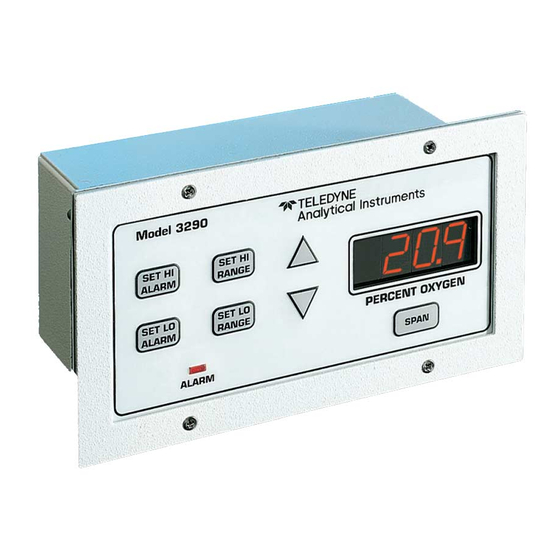
Page 12: Front Panel Description
Introduction Model 3290 User selectable autoranging feature, which allows the analyzer to automatically select the proper preset range for a given measurement. The analyzer can also be manually locked on a fixed analysis range. Two concentration alarms with adjustable setpoints. - Page 13 Meter Readout: As the meter readout, it displays the oxygen concentration currently being measured. Measurement Parameters Readout: It also displays user-definable alarm setpoints, ranges, and span calibration point when they are being checked or changed. Teledyne Analytical Instruments...
-
Page 14: Rear Panel Description
Introduction Model 3290 1.4 Rear Panel Description The rear panel contains the electrical input and output connectors. Separate rear panel illustrations are shown in Figure 1-2 for the AC and DC powered versions of the instrument. The connectors are described briefly here and in detail in Chapter 3 Installation of this manual. - Page 15 Alarm Connections HI Alarm, LO Alarm, and Sensor Failure Alarm connections. RS-232 Port Serial digital output of concentration and range signals. (Option) External Probe Connects to the Remote Probe or remote Analysis Unit. Teledyne Analytical Instruments...
- Page 16 Introduction Model 3290 Teledyne Analytical Instruments...
-
Page 17: Operational Theory
2.2 Oxygen Sensor 2.2.1 Principles of Operation The oxygen sensor used in the Model 3290 is a micro-fuel cell designed and manufactured by TAI. It is a sealed, disposable electrochemical transducer. The active components of the oxygen sensor, also referred to as the... -
Page 18: Anatomy Of The Oxygen Sensor
Operational Theory Model 3290 therefore a hybrid between a battery and a true fuel cell; where in a true fuel cell all of the reactants are stored externally. 2.2.2 Anatomy of the Oxygen Sensor The oxygen sensor is made of extremely inert plastic (which can be placed confidently in practically any environment or sample stream). -
Page 19: Electrochemical Reactions
The output of the fuel cell is limited by (1) the amount of oxygen in the cell at the time and (2) the amount of stored anode material. In the absence of oxygen, no current is generated. Teledyne Analytical Instruments... -
Page 20: The Effect Of Pressure
The sensing technology deployed in the Model 3290 is an electrochemical oxygen sensor which is a partial pressure device. Any changes in the vent pressure of the unit will affect the pressure of the sample the sensor sees. -
Page 21: Calibration Characteristics
Figure 2-2: Input/Output Curve for a Typical Oxygen Sensor In addition, since there is zero output in the absence oxygen, the characteristic curve has an absolute zero. The cell itself does not need to be zeroed. Teledyne Analytical Instruments... -
Page 22: Electronics
Operational Theory Model 3290 2.3 Electronics 2.3.1 General The signal processing uses an Intel micro-controller with on-board RAM and ROM to control all signal processing, input/output, and display functions for the analyzer. System power is supplied from a universal power supply module designed to be compatible with most international power sources. -
Page 23: Figure 2-3: Block Diagram Of The Signal Processing Electronics
See Specifications in the Appendix. The output from the temperature compensation amplifier is sent to an analog to digital converter (ADC), and the resulting digital concentration signal is sent to the micro-controller. Teledyne Analytical Instruments... - Page 24 Operational Theory Model 3290 The digital concentration signal along with input from the front panel buttons (KEYBOARD) is processed by the micro-controller, and appropriate output signals are directed to the display, alarm relays, and the optional RS-232 output. The same digital information is also sent to a 12-bit digital to analog converter (DAC) that produces the 0-10 VDC analog concentration signal and the 0-10 VDC analog range ID output.
-
Page 25: Installation
TO THE MATERIAL SAFETY DATA SHEET IN THE APPENDIX OR ADDENDUM. ANY DAMAGE OR SCARRING OF THE DELICATE PERMEABLE MEMBRANE ON THE SENSING END OF THE CELL WILL REQUIRE CELL REPLACEMENT. PREVENT CONTACT WITH MEMBRANE BY ANY SOLID OBJECT. Teledyne Analytical Instruments... -
Page 26: Unpacking The Analyzer
3.2 Location and Mounting 3.2.1 Control Unit Installation The 3290 Control Unit is designed to be panel-mounted in a general purpose, indoor area, away from moisture and the elements. The unit should be installed at viewing level in a sheltered area. -
Page 27: Installing The Oxygen Sensor
To install or replace the oxygen sensor, follow the procedures in Chapter 5, Maintenance. 3.3 Electrical Connections Figure 3-1 shows the two alternate Model 3290 rear panels. The difference between them is the power connections. The first illustration shows the AC powered version, and the second illustration shows the DC powered version. -
Page 28: Figure 3-1: Rear Panel Electrical Connectors For Ac & Dc Units
Installation Model 3290 power cord receptacle, accepts a 5 x 20 mm, 0.5 A, time-lag (T) fuse. (See Fuse Replacement in Chapter 5, Maintenance.) The power switch is located at the right within the power source input receptacle assembly. Figure 3-1: Rear Panel Electrical Connectors for AC & DC Units Primary Input Power (DC version): The 10–36 VDC power is... - Page 29 If power fails the relays de-energize (alarms activated). The contact connections are indicated diagrammatically on the rear panel as Normally Closed, Common, and Normally Open. Figure 3-2 explains how these act in failsafe operation. Teledyne Analytical Instruments...
-
Page 30: Figure 3-2: Contact Identification For Failsafe Relay Operation
The RS-232 protocol allows some flexibility in implementation in the choice of values for certain parameters. Table 3-1 lists the RS-232 values required by the Model 3290 implementation. Note: The RS-232 port is an optional feature and is not present on all instruments. -
Page 31: Gas Connections
Gas connection instructions depend on the specific External Probe used and any special requirements of the process being monitored. The standard Model 3290 External Probe has inlet and outlet fixtures only. Calibration gases must be tee’d into the sample inlet through appropriate valves. -
Page 32: Installation Checklist
Installation Model 3290 3.5 Installation Checklist Before connecting the instrument to the power source and turning it on, make sure you have: Correctly installed the Sample and Exhaust gas lines Opened the isolation valves Checked for leaks ... -
Page 33: Operation
Analyzing for the percent oxygen level in the gas passing through the cell block is the default mode of operation. As long as no front panel buttons are being pressed, the Analyzer is analyzing. Figure 4-1: Front Panel Controls and Indicators Teledyne Analytical Instruments... -
Page 34: Using The Function And Data Entry Buttons
Operation Model 3290 4.2 Using the Function and Data Entry Buttons When no buttons on the Analyzer are being pressed, the instrument is in the Analysis mode. It is monitoring the percent of oxygen in the sample gas that is flowing through the remote probe. -
Page 35: Hi Range
1. Press the function button once. SET HI ALARM 2. Immediately (within 5 seconds) press either the or button to raise or lower the displayed value, as required, until the display reads the desired percent concentration. Teledyne Analytical Instruments... -
Page 36: Lo Alarm
4.5 Selecting a Fixed Range or Autoranging The Model 3290 can operate in fixed high, fixed low, or autoranging mode. To change modes: 1. Press and then release the... - Page 37 Allow time for the sampling system to purge and the analyzer to achieve equilibrium. Note: Teledyne recommends not to use breathing air cylinders as a calibration source since the oxygen concentration has been found to vary between 19.5-23.5% oxygen. Always...
- Page 38 Operation Model 3290 Teledyne Analytical Instruments...
-
Page 39: Maintenance
Maintenance Maintenance Aside from normal cleaning and checking for leaks at the gas connections, the Model 3290 should not require any maintenance beyond replacement of expended sensors, and perhaps a blown fuse. Routine maintenance includes occasional recalibration, as described in Chapter 4, Operation. -
Page 40: Dc Powered Units
Maintenance Model 3290 3. Insert a small flat-blade screwdriver into the slot in the receptacle wall nearest the fuse and gently pry open the fuse receptacle. The fuse holder will slide out. The fuse in use is visible in the clip. -
Page 41: Ordering And Handling Of Spare Sensors
USED. IF THE CELL PACKAGE IS PUNCTURED AND AIR IS PERMITTED TO ENTER, CELL-LIFE WILL BE COMPROMISED. CAUTION: THE SENSOR USED IN THE MODEL 3290 USES ELECTROLYTES WHICH CONTAIN SUBSTANCES THAT ARE EXTREMELY HARMFUL IF TOUCHED, SWALLOWED, OR INHALED. AVOID CONTACT WITH ANY FLUID OR POWDER IN OR AROUND THE UNIT. -
Page 42: Removing The Oxygen Sensor
Maintenance Model 3290 5.2.3 Removing the Oxygen Sensor No tools are required to replace the cell in the instrument for either the standard E-2 sensor or the optional C-5 or C-5F sensors. To remove a spent or damaged E-2 oxygen sensor: 1. -
Page 43: Cell Warranty Conditions
5. Reconnect power to the instrument. 5.2.5 Cell Warranty Conditions The E-2 oxygen sensor is the typical cell used in the Model 3290. This cell is a long life cell and is warranted for 2 years (under specified operating conditions—see Appendix) from the date of shipment. Note any Addenda attached to the front of this manual for special information applying to your instrument. - Page 44 Maintenance Model 3290 If a cell was working satisfactorily, but ceases to function before the warranty period expires, the customer will receive credit toward the purchase of a new cell. With any warranty claim, the customer must return the cell in question to the factory for evaluation.
-
Page 45: Appendix
Response Time: 90% in less than 20 seconds at 77°F (25 °C) System Power Requirements: AC (100 to 240 VAC, 50/60 Hz), or DC (10-36 VDC, 15 W); user specified Power Consumption: 70 Watts Teledyne Analytical Instruments... -
Page 46: Spare Parts List (Standard Version)
Maintenance Model 3290 System Enclosure: Panel Mount: 2.81" H × 6.0" W × 2.87" D (71.4 mm × 152.4 mm × 72.9 mm) Face Plate: 3.75" H × 7.0" W (95.3 mm H × 177.8 mm W) Sensor Type: E-2 (typical) C-5, C-5F (optional) Analysis Unit: 4.0"... -
Page 47: Drawing List (Standard Version)
Outline Diagram C-64643 Final Assembly (and interconnection diagram) C-64773 Control Unit Assembly C-65946 Analysis Unit Assembly A.4 Miscellaneous The symbol: ~ is used on the rear panel of the Model 3290 to signify volts alternating current (VAC). Teledyne Analytical Instruments...
Need help?
Do you have a question about the 3290 and is the answer not in the manual?
Questions and answers