Table of Contents
Advertisement
Quick Links
®
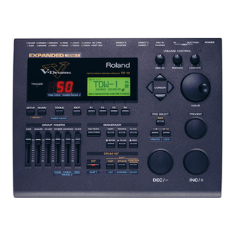
We'd like to take a moment to thank you for purchasing the Roland Percussion
Sound Module TD-10.
Before using this unit, carefully read the sections entitled: "IMPORTANT SAFETY
INSTRUCTIONS" (p. 2), "USING THE UNIT SAFELY" (p. 3, 4), and "IMPORTANT
NOTES" (p. 17). These sections provide important information concerning the
proper operation of the unit. Additionally, in order to feel assured that you have
gained a good grasp of every feature provided by your new unit, this manual should
be read in its entirety. The manual should be saved and kept on hand as a
convenient reference.
Copyright © 1997
ROLAND CORPORATION
All rights reserved. No part of this publication may be reproduced in
any form without the written permission of ROLAND CORPORATION.
Advertisement
Table of Contents
Troubleshooting

Related Manuals for Roland V-DRUMS TD-10


Summary of Contents for Roland V-DRUMS TD-10
- Page 1 ® We’d like to take a moment to thank you for purchasing the Roland Percussion Sound Module TD-10. Before using this unit, carefully read the sections entitled: “IMPORTANT SAFETY INSTRUCTIONS” (p. 2), “USING THE UNIT SAFELY” (p. 3, 4), and “IMPORTANT NOTES”...
-
Page 2: Important Safety Instructions
The lightning flash with arrowhead symbol, within an CAUTION equilateral triangle, is intended to alert the user to the RISK OF ELECTRIC SHOCK presence of uninsulated “dangerous voltage” within the DO NOT OPEN product’s enclosure that may be of sufficient magnitude to ATTENTION : RISQUE DE CHOC ELECTRIQUE NE PAS OUVRIR constitute a risk of electric shock to persons. -
Page 3: Using The Unit Safely
• When using the unit with a rack or stand recom- tion on the cord to heat up and eventually melt mended by Roland, the rack or stand must be care- through. fully placed so it is level and sure to remain stable. If ...................... - Page 4 USING THE UNIT SAFELY • Always grasp only the plug on the power-supply cord when plugging into, or unplugging from, an outlet or this unit......................• Try to prevent cords and cables from becoming entangled. Also, all cords and cables should be placed so they are out of the reach of children.
-
Page 5: How To Read This Owner's Manual
How to read this owner’s manual This owner’s manual is organized as follows. Quick Start This section is intended for those using the TD-10 for the first time, and explains how to use various functions in a simple way. Please read Quick Start and follow along by actually operating the TD- 10. -
Page 6: Table Of Contents
Contents IMPORTANT SAFETY INSTRUCTIONS ................2 USING THE UNIT SAFELY....................3 How to read this owner’s manual ..................5 Features ..........................12 Front and rear panel......................14 Important notes .........................17 About button operations and the screen displays .............18 Quick Start ......21 Before you begin playing......22 Mounting the TD-10 to the stand..................22 Connect your audio system or amp...................23 Connecting pads and pedals.....................24... - Page 7 Contents Modifying a drum kit ........54 [INST]: Creating drum sounds ..................55 Selecting an instrument........................55 Modify the material and depth of the body..................56 Change the material and tuning of the head ..................58 Adjust the muffling (muting) and snare strainer tension .............60 [STUDIO]: Adjusting the acoustics of the room..............62 Decide “where”...
- Page 8 Contents Chapter 3. Instrument settings ....80 Selecting an instrument.....................80 Selecting instruments from the list display ................80 Editing an acoustic drum kit (V-EDIT) ................81 Selecting the shell material ........................81 Changing the shell depth........................82 Selecting the head material........................82 Tuning the head ..........................82 Muffling settings (muting) ........................83 Adjusting the snare strainer tension ....................83 Editing an electronic drum kit (V-EDIT) ................84...
- Page 9 Contents Chapter 6. Sequencer........97 Basic sequencer operation....................97 Using Preset Patterns .........................97 Setting the tempo ......................97 Setting the tempo for each pattern ....................97 Temporarily changing the tempo of the currently-playing pattern..........97 Playback functions ......................98 Selecting a pattern..........................98 Selecting patterns from the list ......................98 Selecting how a pattern will playback.....................98 Click settings ........................99 Click on/off and volume settings ....................99...
- Page 10 Selecting the note number transmitted by each pad ..............122 Setting the Gate Time ........................123 Setting the MIDI channel .........................123 Using the TD-10 with the Roland SPD-11...............123 MIDI settings for the entire TD-10 ...................124 Setting the MIDI channels for each Part..................124 Turning off Local Control........................124...
- Page 11 Contents MIDI messages for detailed performance expressions ...........128 Messages for hi-hat control ......................128 Messages for positional sensing (snare drum and ride cymbal only)........129 Synchronization with external MIDI devices..............129 Appendices......131 Troubleshooting.......................132 Instruments that can be used with each trigger...............136 Restoring the factory settings (INITIALIZE)..............137 Message / error message list ..................138 About MIDI ........................140 Using drum triggers ......................142...
-
Page 12: Features
In addition, when PD-100 or PD-120 (optional) pads are used, you can enjoy excellent response when playing rolls. * COSM (Composite Object Sound Modeling) is a Roland technology which combines multiple sound model- ing processes to create new sounds. - Page 13 Features Functions and operations perfect for live performances The group faders on the front panel let you make quick changes as needed during performance. You can play drum kits in any desired order (Drum Kit Chain). The INC/DEC buttons are large enough to be pressed with a drum stick.
-
Page 14: Front And Rear Panel
Front and rear panel Front Panel 12 13 14 Trigger Indicator EXIT Button This will light when a trigger signal (signal produced when Press this button and you will return to the screen one level pad is struck) is received from a pad. It allows you to check higher in the hierarchy. -
Page 15: Group Faders
Front and rear panel GROUP FADERS TRIG SELECT These allow you to adjust the volume of the kick, snare, hi- Use the lower two buttons to select the pad (trigger number) hat, other percussion instruments, backing instruments, and for which you wish to make settings. To select the rim of a the click sound (p. -
Page 16: Rear Panel
Front and rear panel Rear Panel MEMORY CARD Slot PHONES Jack An M-512E memory card (optional) can be inserted into this A pair of stereo headphones can be connected to this jack. slot. Each memory card can store all settings of the TD-10, Even if headphones are connected, sound will still be output such as drum kits and sequencer performance data, etc (p. -
Page 17: Important Notes
Afterwards, be sure to wipe Use a cable from Roland to make the connection. If using the unit thoroughly with a soft, dry cloth. some other make of connection cable, please note the fol- Never use benzene, thinners, alcohol or solvents of any lowing precautions. -
Page 18: About Button Operations And The Screen Displays
About button operations and the screen displays Operations common to all aspects of operating the TD-10 are covered below. Saving your settings For operations within the TD-10, there is no procedure for “saving settings.” When you modify the value of a setting, the new value is automatically saved as soon as you make the change. Buttons, sliders and knobs Buttons, sliders and knobs on the front panel will be printed in square brackets [ ];... - Page 19 About button operations and the screen displays How to modify settings fig.00-005e INC/DEC button VALUE dial [INC] and [DEC] (referred to in this manual as [INC/DEC]) and the VALUE dial are both used to modify the values of settings. The two methods have the following advantages. [INC/DEC] •...
-
Page 20: About The Preset Drum Kits
About button operations and the screen displays Selecting pads from the TD-10 front panel fig.00-008 The trigger select buttons ([TRIG SELECT]) are used when you wish to select a sound for editing from the front panel of the TD-10, rather than by striking a pad as explained above. You can use these buttons to select a trigger number and edit the settings. -
Page 21: Quick Start
Quick Start... -
Page 22: Before You Begin Playing
Before you begin playing This section explains the connections and settings that you must make before playing. The explana- tions here are given, assuming that the TD-10 has its factory settings. The TD-10 provides a function for restoring the factory settings. Refer to “Restoring the factory settings (INI- MEMO TIALIZE)”... -
Page 23: Connect Your Audio System Or Amp
Before you begin playing Connect your audio system or amp To prevent malfunction and/or damage to speakers or other devices, always turn down the volume, and turn NOTE off the power on all devices before making any connections. fig.00-010e Audio cable Power cord to AC power outlet... -
Page 24: Connecting Pads And Pedals
Using the cables provided, connect your pads, hi-hat control pedals and kick trigger units as shown in the above diagram. Special jacks are provided for the kick (KICK) and snare (SNARE), so make the correct connections to these jacks. fig.00-011e TD-10 Rear panel Roland... - Page 25 Before you begin playing If you are using a PD-7 or PD-9, move the polarity switch located on the back of the pad to the “-(Roland)” NOTE position. When using a KD-7, either position will do. fig.00-012 OUTPUT POLARITY - (Roland)
-
Page 26: Turning On The Power
Before you begin playing Turning on the power Once the connections have been completed (p. 23, 24), turn on power to your various devices in the order spec- NOTE ified. By turning on devices in the wrong order, you risk causing malfunction and/or damage to speakers and other devices. -
Page 27: To Turn The Power Off
Before you begin playing Turn on the power of the connected amp or audio system. Raise the [GROUP FADERS] sliders to the maximum position, and adjust [MASTER] ([PHONES]) to the position shown in the diagram. fig.00-014a While striking [PREVIEW] with your finger, adjust the volume of the connected amp or audio sys- tem. -
Page 28: Listening To The Internal Demo Playback
Before you begin playing Listening to the internal demo playback The TD-10 contains demo songs that demonstrate its sounds and expressive capabilities. The demo song is a “rainbow” of 4 short songs, arranged as a medley. It plays back in “loop” (repeating) mode, yet you can also listen, starting from any of 4 positions, accessed as follows: fig.00-015 Set each of the [GROUP FADERS] sliders [KICK][SNARE][HI-HAT][OTHERS][BACKING] to the... -
Page 29: Specify The Pads That The Td-10 Will Use
Before you begin playing Specify the pads that the TD-10 will use In order for the TD-10 to accurately receive trigger signals from each pad, you must specify the type of pad that is connected to each TRIGGER INPUT jack. If you have purchased the “V-Basic Kit”... -
Page 30: If You Have Purchased The Pd-5, Pd-7, Pd-9, Pd-100 Or Pd-120 Individually
Before you begin playing If you have purchased the PD-5, PD-7, PD-9, PD-100 or PD-120 individually Make the following settings for each pad. fig.00-023 Press [SETUP], press [F1 (TRIG)], and then press [F1 (BANK)]. The following screen will appear: fig.00-017 This screen shows a list of pad models that are specified for each TRIGGER INPUT jack. -
Page 31: Adjusting The Head Tension
Before you begin playing Adjusting the head tension For these pads, adjustments are required in order to regularize the tension of the head. Also, the ten- sion of the head may change when the pad has been used for a long period. If this occurs, use the following procedure to make adjustments as necessary. - Page 32 Before you begin playing On the head of the PD-100 or PD-120, accurately strike a location approximately 1 inch (3 cm) from the tuning bolt. fig.00-027e Strike here Tuning bolt 1 inch (3 cm) The indicator in the lower right of the display will indicate how far off the adjustment is. Use a tuning key (optional) to turn the all tuning bolt so that the indicator reaches the position shown in the diagram.
-
Page 33: Using Triggers On An Acoustic Drum To Play The Td-10
Before you begin playing Using triggers on an acoustic drum to play the TD-10 Set the trigger type to the drum trigger setting, and if notes are not sounded accurately, you’ll need to make changes in the “advanced” mode of this section. For details, refer to “Detailed settings for the trigger parameters (ADVNCD)”... -
Page 34: Check The Settings
Before you begin playing Check the settings This completes the settings. Strike the pads/drums and verify that the appropriate instrument sounds correctly. If not, check the settings once again, and refer to “Troubleshooting connections and settings” on p. 45. -
Page 35: For A Better Performance
For a better performance Concerning the performance & expressiveness of the pads This section introduces various performance functions that will help you perform more expressively on the pads. Some of these playing techniques and functions are unique to the TD-10, so please be sure to read this section in order take full advantage of the TD-10’s capabilities. -
Page 36: Positional Sensing
For a better performance Positional sensing This function simulates movement across the snare drum head or ride cymbal surface. A PD-7, PD- 9, PD-100 or PD-120 can be used when connected to trigger jacks number 2 or 10. fig.00-032e Tonal differences by strike location For the snare drum and ride cymbals, differences in striking position between the center of the head and the rim area will produce a natural change in tone. -
Page 37: Td-10 Operating Procedure
For a better performance TD-10 operating procedure This section explains basic operation of the TD-10. Please try out each of these procedures. Adjusting the volume Adjusting the volume balance For the kick drum, snare drum and hi-hat, use the [GROUP FADERS] sliders to adjust the volume. Tom and cymbal, etc. -
Page 38: Selecting A Drum Kit
For a better performance Selecting a drum kit fig.00-036 Press [KIT]. The following screen will appear: fig.00-037 Each drum kit of the TD-10 is a collection of settings for the instrument assigned to each pad, set- tings for the room and microphones, mixer, effects and other parameters. Use [INC/DEC] or the VALUE dial to select a kit. -
Page 39: Adjusting The Sensitivity Of A Pad
For a better performance Adjusting the sensitivity of a pad You may wish to adjust the sensitivity of the pads to accommodate your personal taste. In this sec- tion we will explain the easiest way to adjust the TD-10’s sensitivity in order to get the best correla- tion between your playing velocity (strength) and the response and volume of the sound. -
Page 40: Master Equalizer
For a better performance Master equalizer This is the master equalizer that is applied to the sound output from the MASTER OUT jacks. It adjusts the balance of the low, mid, and high frequency ranges. Let’s try adjusting the GAIN (the amount of boost). -
Page 41: Effect On/Off
For a better performance Effect on/off If you wish to compare your sounds “with” or “without” ambiance, individual compressors & equalizers, or digital effects, here they can each be turned on/off for the entire kit. fig.00-040 Press [KIT], and then press [F3 (FX SW)]. The following screen will appear: fig.00-041 In this page, [F1]–[F4] act as on/off switches. -
Page 42: Help Function
For a better performance Help function You can select a keyword for a specific operation and instantly view an explanation or the relative setting page. For example if you wish to make settings for a function using a foot switch, select the “FOOT SWITCH”... -
Page 43: About Expansion Boards
Expansion boards (optional) are cards that allow you to upgrade the system and add new instru- ments and drum kits. * Sound expansion boards for the Roland JV/XP series cannot be used. The bottom panel of the TD-10 has a slot that allows expan- 5. -
Page 44: À Propos Des Cartes D'extension
Les cartes d’extension (optionnelles) sont des cartes qui vous permettent d’augmenter la puissance de votre système et d’ajouter de nouveaux instruments ainsi que des batteries. * Les cartes d’extension de son pour les séries JV/XP de Roland ne peuvent être utilisées. N’installez que la ou les carte(s) de circuits imprimés spéci- 5. -
Page 45: Troubleshooting Connections And Settings
“Troubleshooting” (p. 132) in the “Appendices.” Also refer to that section if you are using acoustic drums to trigger the TD-10, or if you are using pads made by a manufacturer other than Roland. No sound... - Page 46 • When using a PD-7 or PD-9, is the Polarity Switch set to “- ters (BASIC)” (p. 109) in the “Advanced Use,” and make the (Roland)”? needed changes or settings. • Strike location can be detected only for trigger number 2 (SNARE) and trigger number 10 (RIDE).
-
Page 47: Features Of The Preset Drum Kits
Features of the preset drum kits How sounds are created on the V-drums The TD-10 uses a completely new method for generating sounds called Variable Drum Modeling. The concept of this method is to “model” the important parts or “character” that makes a drum sound the way it does. -
Page 48: No.36: 70'S Rock Drum Kit
Features of the preset drum kits No.36: 70’s Rock drum kit This is a rock drum kit with a deep and “fat” sound. Until now, this type of “fatness” could never be created or edited in drum modules or samplers. However, since the TD-10 uses a model of an acoustic drum that can be adjusted using the Variable Drum Modeling technology, you can create a sound of your own and one that responds to your natural dynamics. - Page 49 Features of the preset drum kits Press [INST], then [F2 (EDIT)], and then press [F1 (SHELL)]. The following screen will appear: fig.00-058 Strike the pad that you are using as the snare. The snare settings display page will appear. In this page you can select the materials and depth of the drum shell.
-
Page 50: No.37: Brush Kit
Features of the preset drum kits No.37: Brush Kit This is a kit for playing with brushes, something that was also not possible with any previous elec- tronic drum system. Compared with stick playing, brush playing uses an extremely delicate trigger signal, so we have provided a kit with special trigger settings. - Page 51 Features of the preset drum kits Press [F3 (FX SW)]. The following screen will appear: fig.00-066 An indication of “ON” appears above each button [F1]–[F4], indicating that all effects are being used. Press [F1] and [F4]. Ambiance and Effect will be turned off. fig.00-067 How does it sound? You will notice that the sound has suddenly lost its sense of depth.
-
Page 52: No.38: Electronic Drum Kit
Features of the preset drum kits No.38: Electronic drum kit With this kit we can reproduce the electronic drums that were popular in the early 1980’s. Previous drum sound modules did not provide for the creation and editing of the unique parameters of an electronic drum. - Page 53 Features of the preset drum kits Press [INST], and then press [F2 (EDIT)]. The following screen will appear: fig.00-072 Strike the pad that is being used as the tom. The tom setting screen will appear. Press [CURSOR] to move the cursor to “Bend.” fig.00-073 While using [INC/DEC] or the VALUE dial to increase the pitch bend setting, strike the tom pad.
-
Page 54: Modifying A Drum Kit
Modifying a drum kit In this section we will start with drum kit number 36, and take you through the process of creating an entirely different kit. Kit number 36 is a distinctive kit intended for rock, but we will turn this into a sharper and more natural-sounding drum kit that might be suitable for fusion, etc. -
Page 55: [Inst]: Creating Drum Sounds
Modifying a drum kit [INST]: Creating drum sounds The settings in this section are for the drums themselves, and they are concerned with the funda- mental elements that determine the character of the sound. Via easy operations you can proceed through the process of selecting an instrument, deciding its material and shape, and adjust the tun- ing, etc. -
Page 56: Modify The Material And Depth Of The Body
Modifying a drum kit Modify the material and depth of the body By changing the material of the instrument body and listening to the difference, you can find the sound that you want. This is an editing method that is only possible on the TD-10. It’s just like choosing between a variety of real snare drums. - Page 57 Modifying a drum kit Use [INC/DEC] or the VALUE dial to change the material of the body. In this example, let’s change the setting from “Steel” to “Wood.” Of the three types, this will pro- duce the warmest sound. fig.00-084 This completes our selection of the body material.
-
Page 58: Change The Material And Tuning Of The Head
Modifying a drum kit Change the material and tuning of the head Here, let’s modify the type and tuning of the snare drum head. fig.00-088 Press [INST], then press [F2 (EDIT)], and then press [F2 (HEAD)]. Strike the pad being used for the snare. The snare setting page appears. - Page 59 Modifying a drum kit This completes the head material choice. Next we’ll tune of the head. Use [CURSOR] to move the cursor to “Head Tuning.” fig.00-091 Use [INC/DEC] or the VALUE dial to modify the tuning. Here we will change the setting from “-30” to “0.”...
-
Page 60: Adjust The Muffling (Muting) And Snare Strainer Tension
Modifying a drum kit Adjust the muffling (muting) and snare strainer tension You can add muffling to the snare drum or adjust the tension of the snare strainer to reduce unwant- ed overtones or resonances, creating a tighter sound. You can even turn the snares off! fig.00-093 Press [INST], then press [F2 (EDIT)], and then press [F3 (MUFFLE)]. - Page 61 Modifying a drum kit Use [INC/DEC] or the VALUE dial to modify the setting. For this example, select “Dougnuts1.” The sound will become somewhat more muted. fig.00-095 This completes the muffling settings. Next we will adjust the tension of the strainer. Use [CURSOR] to move the cursor to “Strainer Adj.”...
-
Page 62: [Studio]: Adjusting The Acoustics Of The Room
Modifying a drum kit [STUDIO]: Adjusting the acoustics of the room One very important element that affects the overall sound of a drum kit is the environment in which the drums are placed. The same drums are capable of producing a very different sound, depending on whether they are played in a conventional studio, or in a glass-walled room. -
Page 63: Decide "Where" The Drums Are Played
Modifying a drum kit Decide “where” the drums are played You can choose locations for your drums from different types of rooms, a cave, a bathroom or even the beach. You make this selection by “seeing” the icon that represents the actual acoustical environ- ment. -
Page 64: Change The Size Of The Room
Modifying a drum kit Change the size of the room You can modify the “ambience” space by selecting one of five different room sizes. fig.00-103a Press [STUDIO], and then press [F2 (ROOM)]. The following screen will appear: fig.00-103 Use [CURSOR] to move the cursor to “Room Size.” Use [INC/DEC] or the VALUE dial to modify the setting. -
Page 65: [Control Room]: Adding Finishing Touches To The Sound
Modifying a drum kit [CONTROL ROOM]: Adding finishing touches to the sound Using the equalizer to modify the sound If you want the selected instrument to sound a little different, such as “a bit brighter” or “a bit lighter,” etc., you can use the equalizer to make adjustments. The TD-10 has a 2-band (high and low) equalizer for each instrument, and this can be used to fine tune each sound for the total blend of the kit. - Page 66 Modifying a drum kit In this example, let’s assume that we want to make the sound of the snare stand out. fig.00-107 Press [CONTROL ROOM], press [F3 (EQ)], and then press [F4 (HIGH)] The following screen will appear: fig.00-108 Strike the pad being used for the snare. The snare setting screen will appear.
-
Page 67: Adjusting The Volume Balance Of The Instruments
Modifying a drum kit Adjusting the volume balance of the instruments Now that we’ve used the equalizer to boost the high range, the snare sounds brighter. With this change, however,the snare might stand out a bit too much. Let’s lower the volume to correct the bal- ance. -
Page 68: Examples And Convenient Tips
Examples and convenient tips This section will highlight things that are possible only with electronic musical instruments such as the TD-10. Perform with the on-board sequencer The TD-10 contains a sequencer that can record and play back accompaniment tracks and/or drum performances. -
Page 69: Play The Pads Along With A Preset Pattern
Examples and convenient tips Play the pads along with a preset pattern When you have found a preset pattern that you like, you can play along with that pattern. While sounding the click, adjust the volume balance of the drums, backing parts, and the click. fig.00-117 Adjust the [BACKING] and [CLICK] [GROUP FADERS] lower than the other sliders. -
Page 70: Drum Kit Chain-Selecting Drum Kits In The Desired Order
Examples and convenient tips Drum Kit Chain—Selecting drum kits in the desired order You can choose the order in which drum kits will be selected. fig.00-120 Press [CHAIN], and then press [F1 (C.EDIT)]. The following screen will appear: fig.00-121 In this screen, you can create a list to specify the order in which the drum kits will be selected. Use [CURSOR] to move the cursor to the sequence order in which the drum kits will be selected—... - Page 71 Examples and convenient tips Use [INC/DEC] or the VALUE dial to select the kit that will be selected second. In the same way, make settings for the third and subsequent kits. fig.00-122 To delete an unwanted kit from a step, use [CURSOR] in the “CHAIN” page to select the kit, and then press MEMO [F2 (DELETE)].
-
Page 72: Using A Foot Switch To Select Kits
Examples and convenient tips Using a foot switch to select kits When an FS-5U foot switch (optional) is connected to the FOOT SWITCH jack, you can use it to select kits, patterns, or as a play/stop button for patterns (p. 120). fig.00-123e Foot switch cable PCS-31 Foot switches... -
Page 73: Using Headphones To Hear The Click Sound
Examples and convenient tips Using headphones to hear the click sound If you want to listen to a click sound while you play (for example during practice or a live perfor- mance), you can make settings so that the click is heard only in the headphones, and is not output from the OUTPUT jacks (MASTER). -
Page 74: Using The Td-10 As A Midi Sound Module
Examples and convenient tips Using the TD-10 as a MIDI sound module The TD-10 can also be used as a sound module for MIDI keyboards or sequencer. When used as a MIDI sound module, the percussion group (p. 126) can be used so that 72 types of instrument can be accessed simultaneously in addition to the sounds that are assigned to the 12 trigger inputs (pads). -
Page 75: Advanced Use
Advanced Use... -
Page 76: Chapter 1. Overview Of The Td-10 V-Drums
Chapter 1. Overview of the TD-10 V-drums The TD-10 is a drum trigger interface and sound module, providing virtual reproduction of an actu- al drum set, allowing total control over all aspects of drum sound creation. When electronic drums were first developed, the technology available was not as advanced as it is today, so sounds were not really comparable with acoustic drums. -
Page 77: How To Select Pads
Chapter 1. Overview of the TD-10 V-drums How to select pads When making settings, you can specify the pad in one of the following two ways. Using pads to select the pad/sound for editing Strike the head (the head and rim simultaneously) of the pad. The setting display for the pad you struck will appear. -
Page 78: Chapter 2. Settings For The Entire Drum Kit
Chapter 2. Settings for the entire drum kit Selecting a kit Naming a kit Press [KIT], and the basic display page will appear. In this Each kit can be given a name of up to 8 characters. fig.03-01 page, you can use [INC/DEC],the VALUE dial or a foot switch (optional) to select drum kits (p. -
Page 79: Making Settings For Brush Performance
Chapter 2. Settings for the entire drum kit Making settings for brush Effect switches for the performance entire kit For each kit you can specify whether sticks or brushes will Ambience, compressors, equalizers, and digital effects can be used. When the trigger setting is set to “brush,” pad sen- be turned on/off for the entire kit. -
Page 80: Chapter 3. Instrument Settings
Chapter 3. Instrument settings Here you can edit the instruments.(i.e. snare drum kick etc.) Selecting instruments The TD-10 provides separate parameters for editing acoustic from the list display or electronic drum sounds. Here you can choose the sound from the list of all instru- Selecting an instrument ments. -
Page 81: Editing An Acoustic Drum Kit (V-Edit)
Chapter 3. Instrument settings Editing an acoustic drum kit (V-EDIT) V-EDIT and EDIT Editing procedure for an acoustic snare, kick and tom drums will differ depending on the type of instrument and the TRIGGER INPUT jack that you are using. 1. -
Page 82: Changing The Shell Depth
Chapter 3. Instrument settings Changing the shell depth Parameters Head Type: Clear, Coated, PinStripe Changing the depth of the drum shell will change the tone. Clear: A single transparent head. With the snare drum, the depth can be changed over 39 Coated: The most commonly used type of head. -
Page 83: Muffling Settings (Muting)
Chapter 3. Instrument settings Muffling settings (muting) Adjusting the Snare strainer tension You can literally apply tape or “rings” to dampen the over- tones. The amount of contact between the bottom head and the fig.04-08 snares themselves can be adjusted to change the tone just like with a real acoustic drum. -
Page 84: Editing An Electronic Drum Kit (V-Edit)
Chapter 3. Instrument settings Editing an electronic Parameters Instruments from the “ELECTRONIC” instrument group drum kit (V-EDIT) provide the following parameters. Atk (Attack Level ): 0–127 Electronic drum sounds consist of “tone” and “noise.” These Adjusts the volume of the attack (the beginning of the instruments can be assigned only to specific trigger inputs. -
Page 85: Editing A Tr-808/909 (V-Edit)
Chapter 3. Instrument settings Editing a TR-808/909 (V-EDIT) This simulates a Roland “TR-808” or “TR-909” Rhythm Composer. Only instruments specified for each trigger input can be selected. For details on instrument assignments, refer to p. 136. * For instruments in the TR-808/909 groups, selecting an instrument for the head will assigns the same instrument for the rim. -
Page 86: Editing Hi-Hat, Cymbals And Percussion
Chapter 3. Instrument settings Editing hi-hat, cymbals and percussion Only pitch and decay can be edited for instruments that are assigned to trigger inputs 7–12. Even for trigger inputs 1-6, only pitch and decay can be edited if the assigned instru- ment is not V-EDIT capable. -
Page 87: Chapter 4. Studio Settings
Chapter 4. Studio settings Here is where you can virtually change the acoustics of the Changing the wall material room in which you are playing the drums. The parameters You can choose from Wood, Plaster or Glass covered walls available here let you select actual room sizes and wall mate- for the room where the drums are being played. -
Page 88: Adjusting The Volume And Output Assignments Of The Ambience
Chapter 4. Studio settings Parameters Settings for each instrument Ambience Mic Positions: Low, High About the basic procedure Low: Often referred to as “floor mikes,” picking up low frequencies of the room, producing a warmer charac- In each page,when you hit the pad for which you wish to ter. -
Page 89: Settings For Each Group
Chapter 4. Studio settings Selecting the type of mike Settings for each group Procedure Settings can be made for the three main instrument groups: 1. Press [STUDIO]-[F1 (MIC)]. the drum kit,the percussion group, and the backing parts. The “MIC” page will appear. * The percussion group is a sound map that can be accessed when 2. -
Page 90: Chapter 5. Control Room Settings
Chapter 5. Control room settings The most important aspect of finalizing the sound in record- Adjusting pan (stereo location) ing or live performances depends on the mixing console. In This adjusts the stereo location of each pad. the Control Room, you’ll find a complete 12-channel mixer fig.06-02 with 10 individual compressors and EQ’s and digital effects, finalizing your sound in a CD-quality state. -
Page 91: Selecting Output Assignments
Chapter 5. Control room settings Selecting output assignments Controlling variations in volume (Compressor) To change the output destination for the sound of each pad note that the vertical lines indicate the TRIGGER INPUT 10 compressors are provided (Triggers 1-10 only) number, and the horizontal lines indicate the OUTPUT Compression is used to “smooth”... -
Page 92: Customizing The Tone (Equalizer)
Chapter 5. Control room settings Customizing the tone (Equalizer) Peak GAIN LShelv HShelv Here you can adjust the high and low frequencies balance for the instrument assigned to each pad. (TRIGGERS 1-10 only) Frequence * This setting is not available for the AUX1,2 trigger inputs. fig.06-06 FREQ Procedure... -
Page 93: Settings For The Entire Drum Kit
Chapter 5. Control room settings Settings for the entire Gate Reverb 1, 2, 3 Non Linear 1, 2 drum kit These effects cut off the reverberation before its natural decay, and have broad applications as the sound will change Adjusting effect Return level in different ways over time for Gate Reverb and Non Linear. -
Page 94: Editing The Effects
Chapter 5. Control room settings Editing the effects Parameters for Delay 1, 2 Delay Time: 0–1200 (ms) Here’s how to set the parameters for each effect type. It’s best Adjust the time from the original sound until the delay is to use Ambience to create the basic overall sound of the drum heard. - Page 95 Chapter 5. Control room settings Parameters for Chorus Delay 1, 2 Parameters for Pitch Shift Delay 1, 2 Rate: 0.1–10.0(Hz) Pitch Shift: -12–0–+12 (semitones) Adjust the modulation frequency of the chorus. Higher set- Specify the amount of pitch change. A setting of +1 raises the tings produce faster modulation.
-
Page 96: Settings For An Entire Group
Chapter 5. Control room settings Parameters for Flying 3D-Delay 1, 2 Adjusting the volume by group Delay Time: 10–1200 (ms) You can adjust the overall volume of the drum kit and per- Adjust the time from the original sound until the delay is cussion group. -
Page 97: Chapter 6. Sequencer
Chapter 6. Sequencer The TD-10’s sequencer consists of four parts (like 4 tracks). Using Preset Patterns The Drum part is used to record/ play back performance It is not possible to modify the settings of a preset pattern. If from the pads or an external MIDI controller. There are three you attempt to modify the settings when a preset pattern is other parts for melodic instruments: Part 1, Part 2 and the selected, the following display will appear. -
Page 98: Playback Functions
Chapter 6. Sequencer Playback functions Selecting how a pattern will playback Selecting a pattern There are three different ways to make a pattern play back. Loop: The pattern will playback, repeating until you Procedure press [STOP]. 1. Press [PATTERN]. One Shot: The pattern will playback once and then stop. Tap: See (p. -
Page 99: Click Settings
Chapter 6. Sequencer Tap: This function is a great performance tool! For Click settings example if you specify “Tap” for a pattern which contains a melody line and assign this Click on/off and volume settings pattern to a pad, you can play the notes of the melody in order each time you strike the pad. -
Page 100: Selecting The Click Sound
Chapter 6. Sequencer Selecting the click sound Adjusting the pan (stereo location) You have a choice of sixteen sounds including a human voice! You can set the pan position of the click. But if you have cho- sen headphones (Phones Only) as the output destination, the Procedure click will be located in the center regardless of this setting. -
Page 101: Recording
Chapter 6. Sequencer Recording Parameters Time Signature: Numerator = 1–13, Denominator = 2, 4, 8, 16 Length (bars): 1–99 Performance on the pads or on an external MIDI keyboard can be recorded. On the TD-10, your performance will be * When the denominator is 16, you cannot set a numerator of recorded exactly as you play it, including hi-hat control from 1 through 3. -
Page 102: The Rehearsal Function
Chapter 6. Sequencer 5. Specify the recording method The Rehearsal function fig.07-09 During recording you can press [REC] to switch between recording and rehearsal modes. This allows you to try out different sounds,fills or phrases without stopping the play- back of the sequencer. Procedure 1. -
Page 103: Correcting Timing As You Record (Quantize)
Chapter 6. Sequencer Correcting timing as you record 9. When the portion to be imported has been recorded, stop playback on the external sequencer and the TD-10 will (Quantize) stop recording. Quantize is a function that corrects inaccuracies of timing while you record. -
Page 104: Erasing A Pattern
Chapter 6. Sequencer Erasing a pattern Procedure 1. Press [PATTERN]-[F3 (EDIT)]-[F1 (ERASE)]-[F3 (MEAS)]. This function erases ONLY the performance data; other set- The “ERASE PATTERN MEASURE” page will appear. tings (such as the number of measures and the time signa- 2. -
Page 105: Copying Selected Measures Of A Pattern
Chapter 6. Sequencer Copying selected measures of Clearing a pattern a pattern This operation deletes ALL data from a pattern, returning all parameters (time signature,length, tempo) to their default You can copy selected measures of a part or pattern. Unlike values. -
Page 106: Connecting Two Patterns
Chapter 6. Sequencer 3. Use [INC/DEC] or the VALUE dial to make the settings. Settings for part instruments 4. Press [F4 (CLEAR)] A confirmation display will appear. * Drum part settings cannot be made here. These settings are made in the Control Room of the drum kit. (refer to p. 90–96). 5. -
Page 107: Mixer Settings For Each Part
Chapter 6. Sequencer Mixer settings for each part Muting a specific part Procedure Procedure 1. Press [PART]-[F2 (MIXER)]. 1. Press [PART]-[F4 (MUTE)]. The mixer setting page will appear. The “PART MUTE” page will appear. 2. Press [F1]–[F4] to select the parameter that you wish to 2. -
Page 108: Chapter 7. Settings For The Entire Td-10
Chapter 7. Settings for the entire TD-10 Changing output assign- Procedure fig.08-02e ment for audio received by Model name the MIX IN jack Selecting the output destination of the sound input from the MIX IN jack. 1. Press [SETUP]-[F1 (TRIG)]-[F1 (BANK)]. Procedure The “TRIGGER”... -
Page 109: Basic Settings For The Trigger Parameters (Basic)
Chapter 7. Settings for the entire TD-10 Basic settings for the trig- 4. Use [INC/DEC] or the VALUE dial to make the setting. Gradually raise the Threshold value until the kind of unin- ger parameters (BASIC) tentional triggering shown above no longer occurs. However if this value is raised too far, playing softly on the pad will When you are using pads made by other manufacturers, try not be detected. - Page 110 Chapter 7. Settings for the entire TD-10 EXP1, EXP2: Compared to Linear, a wider volume change Head Tension Adjustment will occur for stronger hits. The Head Tension Adjustment parameter regulates the fol- fig.08-06be lowing two adjustments for the PD-100 and PD-120. Press [SETUP]-[F1 (TRIG)]-[F4 (OPTION)] and the setting page will appear.
-
Page 111: Detailed Settings For The Trigger Parameters (Advncd)
Chapter 7. Settings for the entire TD-10 Detailed settings for the trig- Retrigger Cancel (RetrigCancel) fig.08-07 ger parameters (ADVNCD) The following parameters (ADVANCED EDIT) are automat- ically set to the most efficient values for each pad when you select the Trigger Type (p. 108), and don’t require adjust- ment, except if you experience any of the problems that are discussed in the explanation of each parameter. -
Page 112: The Order In Which Trigger Parameters Should Be Set When Using Drum Triggers
Chapter 7. Settings for the entire TD-10 Mask Time (MaskTime) 2. Use [CURSOR] to move the cursor to “Crosstalk.” On a kick pad, for example, if the beater bounces back and 3. Hit the pad for which you wish to make settings and the strikes the pad a second time immediately after the intended setting page for the pad you struck will appear. -
Page 113: Adjusting The Brightness Of The Display
Chapter 7. Settings for the entire TD-10 6. Mask Time Setting the master equalizer Mainly for bass drums so please refer to the explanation above. The master equalizer allows balancing the high, mid, and low frequencies. 7. Crosstalk Same principle as with using pads as as explained above. * This equalizer is not applied to the sound which is output from Once again, press [SETUP]-[F1 (TRIG)]-[F2 (BASIC)] and the the DIRECT 1, 2, 3 jacks. -
Page 114: Saving Data To A Memory Card
Procedure 10 settings and sequencer data. 1. Press [SETUP]-[F4 (UTIL)]-[F1 (SAVE)]. * The Roland M-512E is the ONLY memory card which can be The “Save to CARD” page will appear. used. 2. Move the protect switch on the memory card to the “OFF”... -
Page 115: Loading Data From A Memory Card
Chapter 7. Settings for the entire TD-10 Loading data from a Automatically switching memory card the display (Note Chase) Data saved on a memory card can be loaded into the TD-10. When editing sounds, the TD-10’s display will switch corre- sponding to the sound that is used when a pad is hit (or Procedure when a MIDI message is received). -
Page 116: Chapter 8. Convenient Functions
Chapter 8. Convenient functions Selecting kits in the desired How to use the CHAIN 1. Press [CHAIN] to make the button indicator light order (Drum Kit Chain) The Drum Kit Chain function will be turned on. 2. Use the left/right [CURSOR] or [INC/DEC] to select kits in Specifying a Drum Kit Chain the order that you specified in the chain. -
Page 117: Copying
Chapter 8. Convenient functions Copying “COMPRESSOR/LIMITER” page ([CONTROL ROOM]-[F2 (COMP)]) Compressor settings can be copied to another kit for You can copy drum kits,instruments, mixer & effect settings TRIGGER INPUT jacks 1–10 as a group. etc. to the destination of your choice. However, doing so will “EQ”... -
Page 118: Getting Help
Chapter 8. Convenient functions Getting help Specifying how the Preview button functions The TD-10 comes with a built in “help page” using key- words to select various functions, and a “jump” mode to To audition and edit instruments, tap [PREVIEW]. Press take you to that setting page instantly. -
Page 119: Chapter 9. Operations Using Pads And Foot Switches
Chapter 9. Operations using pads and foot switches By changing the function of controllers or the way in which they are used, you can perform a variety of convenient operations. This opens up some very interesting performance possibilities. Using pads to play patterns (Pad Pattern) You can make settings so that striking a pad will playback a previously selected pattern. -
Page 120: Using Foot Switches To Perform Button Operations (Foot Switch)
Chapter 9. Operations using pads and pedals * If you do not want to trigger instrument sounds assigned to the pads, press [CONTROL ROOM]-[F1 (MIXER)]-[F1 (VOLUME)], and set the volumes of AUX 1 and AUX 2 to “0.” * If the “Mode” setting is “KIT SELECT” or “PATTERN SEL,” striking the rim of the pad will have the same function as pressing [DEC]. -
Page 121: Chapter 10. Functions Using Midi
Chapter 10. Functions using MIDI There are many possibilities when using MIDI, such as: ALL: All data (drum kits, patterns, percus- sion groups, and setup) will be trans- 1. Use an external sequencer to save/load mitted. drum kits, pattern data etc. SETUP: Trigger and pad settings. -
Page 122: Setting The Device Id-Transmitting Saved Data To Two Or More Td-10 Units
Chapter 10. Functions using MIDI Setting the Device ID Using pads to play an —Transmitting saved data to external MIDI sound two or more TD-10 units module The setting described here is necessary only when you wish to transmit separate data to two or more TD-10 units at the Here’s how to make settings. -
Page 123: Setting The Gate Time
(Example) If you decrease the Open Hi-hat note number by “2,” This section explains how you can use the Roland SPD-11 (a the Close and Pedal settings will also decrease by “2.”... -
Page 124: Midi Settings For The Entire Td-10
Chapter 10. Functions using MIDI MIDI settings for the Procedure 1. Press [SETUP]-[F2 (MIDI)]-[F1 (GLOBAL)]. entire TD-10 The “MIDI GLOBAL” page will appear. 2. Use [CURSOR] to move the cursor to “Local Control.” Setting the MIDI channels for 3. Use [INC/DEC] or the VALUE dial to turn the setting each Part “OFF.”... -
Page 125: Using The Td-10 As A Sound Module
Chapter 10. Functions using MIDI Using the TD-10 as a Regarding note numbers for the drum kit sounds sound module Refer to “Selecting the note number transmitted by each As shown in the following diagram, use a MIDI cable to con- pad”... -
Page 126: Using The Percussion Group
Chapter 10. Functions using MIDI Using the percussion group Selecting a percussion group The TD-10 contains four percussion groups and you can The percussion group is used only when playing the TD-10 assign one group per kit. When editing sounds in the per- from an external MIDI controller, keyboard or sequencer. - Page 127 Chapter 10. Functions using MIDI Function buttons Percussion group editing When the cursor is located at the instrument name, you can Each instrument in the percussion group can be edited. fig.11-10 press [F1 (LIST)] to access the instrument list page. Press [F2 (EDIT)] to access the instrument edit page.
-
Page 128: Changing The Kit Number That Is Selected By A Program Change
Chapter 10. Functions using MIDI Changing the kit number that is MIDI messages for selected by a program change detailed performance You can freely select the correspondence between program expressions changes and drum kits, so that (for example) drum kit 10 could be selected when program change number 5 is Messages for hi-hat control received. -
Page 129: Messages For Positional Sensing (Snare Drum And Ride Cymbal Only)
Chapter 10. Functions using MIDI Messages for positional sens- Synchronization with ing (snare drum and ride cym- external MIDI devices bal only) This section discusses the settings that allow an external The TD-10 uses control change messages to indicate the MIDI sequencer and the TD-10’s sequencer to be synchro- position a snare pad or ride cymbal pad was hit. - Page 130 Chapter 10. Functions using MIDI Procedure 1. Press [PATTERN]-[F2 (FUNC)]-[F1 (GLOBAL)]. The “PATTERN GLOBAL” page will appear. 2. Use [CURSOR] to move the cursor to “Sync Mode.” 3. Use [INC/DEC] or the VALUE dial to select “External” or “Auto.” 4. Begin playback on the transmitting device (master). Synchronized playback will begin.
-
Page 131: Appendices
Appendices... -
Page 132: Troubleshooting
Troubleshooting This section outlines points to check if you experience prob- Has a non-volume parameter been set so that no sound can be output? lems, and what to do about them. For matters related to very basic settings, refer to the “Quick Start,” “Troubleshooting Check the following points. - Page 133 Troubleshooting Rotating [MASTER] does not change Equalizer doesn’t work (individual or MASTER) the volume Check the following points by pressing the buttons in the The [MASTER] knob adjusts the volume level from the order given in parentheses ( ) and you’ll access the appro- MASTER jacks, and does not affect the volume of the output priate setting page.
- Page 134 Troubleshooting Hi-hat control pedal (FD-7) does not Sequencer-related problems operate correctly Pressing [PLAY] does not start play- The hi-hat control pedal was not detected correctly at power-on. Turn off the power. Then turn on the power once back again, and do not operate the hi-hat control pedal (FD-7) Are you playing back an empty pattern? until the drum kit display appears.
-
Page 135: Display Is Too Light Or Too Dark
Troubleshooting Display-related problems Other Trigger indicators light on their own Hitting [PREVIEW] plays back a pat- tern. If a monitor speaker or the like is sounding at a high volume nearby a pad, the vibration can sometimes be detected by Is a pad pattern assigned to the pad? the pad as a trigger signal. -
Page 136: Instruments That Can Be Used With Each Trigger
Instruments that can be used with each trigger The instruments that can be assigned to each trigger are as follows. : The instrument can be assigned and V-EDIT is possible : The instrument can be assigned, but V-EDIT is not possible : Cannot be assigned Trigger number Inst group... -
Page 137: Restoring The Factory Settings (Initialize)
Restoring the factory settings (INITIALIZE) If you wish to restore all internal settings to the factory pre- How to recall original factory presets for individual drum set values use the Initialize operation explained below. All kits, percussion groups and trigger banks. fig.12-01ae internal settings will be lost when you perform the Initialize operation, so if necessary, save your data to a memory card... -
Page 138: Message / Error Message List
1. Check whether the card has been used by a different Roland device. Check whether the card has been used by a different Roland Backup Battery Low ! device. If you wish to erase the contents of the card and use The internal backup battery of the TD-10 (a battery that it with the TD-10, press [F4 (ACCEPT)]. - Page 139 (p. 105). SYSTEM ERROR A problem has occurred with the internal system. Contact your dealer or a nearby Roland service center. SYSTEM INITIALIZE Completed ! Initialization of the TD-10’s internal data has been complet- No Empty Pattern There are no more empty patterns.
-
Page 140: About Midi
Functions using MIDI,” and read the section “Using the TD- Sound Module A 10 with the Roland SPD-11” (p. 123). This connector is used Receive when you wish to transmit the same stream of MIDI data to channel : 2... - Page 141 About MIDI How the sequencer operates A sequencer is an electronic musical device that records and plays back performance data, meaning the note you play, how long it is held (gate time) and velocity with which you play, and various controller functions. The TD-10 contains a built-in sequencer with 50 preset patterns containing pre- programmed musical data.
-
Page 142: Using Drum Triggers
Using drum triggers This section explains how to attach an acoustic drum trigger. 2. Use a monaural cable to connect the drum trigger to the TD-10’s TRIGGER INPUT jack. Procedure Drum TRIGGER INPUT jack 1. Attach the drum trigger to the acoustic drum. Kick fig.12-05a Snare drum... -
Page 143: Preset List
Preset list Drum kit list Kit name Percussion group Remark Kit name Percussion group Remark StudioV Far East BigRock SnareBuz Tight HEAVy JazzSizl NextDoor SuperBwl Latin 3D Freak'n Vintage OldScool MIDIbrsh TexMex SockHop GroovIn Woody BtDelayy GoFigure LatinSet 70'sRock Orch Set Brushes BrasRing Electro... -
Page 144: Drum Instrument List
Preset list Drum instrument list Inst name Inst group Remark Inst name Inst group Remark MondVrbK V-KICK VintageK V-KICK Sizzle K V-KICK 26"DeepK V-KICK NailHitK V-KICK ThickHdK V-KICK V-KICK Round V-KICK Dance V-KICK Medium K V-KICK House V-KICK BigRoomK V-KICK Pillow K V-KICK V-KICK... - Page 145 Preset list Inst name Inst group Remark Inst name Inst group Remark Fat2RimS V-SNARE Fat5 SNARE AcusticS V-SNARE Fat5RimS SNARE AcusRimS V-SNARE DynamicS SNARE VintageS V-SNARE DynmcRmS SNARE VntgRimS V-SNARE Roll SNARE Maple1 S V-SNARE Buzz SNARE Mpl1RimS V-SNARE NoSnareS SNARE Jazz V-SNARE...
- Page 146 Preset list Inst name Inst group Remark Inst name Inst group Remark Jazz V-TOM AttackT2 V-TOM Jazz V-TOM AttackT3 V-TOM Jazz V-TOM AttackT4 V-TOM Buzz V-TOM Hall V-TOM Buzz V-TOM Hall V-TOM Buzz V-TOM Hall V-TOM Buzz V-TOM Hall V-TOM Slap V-TOM Birch T1...
- Page 147 Preset list Inst name Inst group Remark Inst name Inst group Remark TR808 T2 TR808 TOM2 China20" CRASH TR808 T3 TR808 TOM3 SzlChina CRASH TR808 T4 TR808 TOM4 SwlChina CRASH TR909 T1 TR909 TOM1 PgyzBack CRASH TR909 T2 TR909 TOM2 PgyCrsh1 CRASH TR909 T3...
- Page 148 Preset list Inst name Inst group Remark Inst name Inst group Remark CongaHOp PERCUSSION Sleibell PERCUSSION CongaHSl PERCUSSION TablaNa PERCUSSION CongaMMt PERCUSSION TablaTin PERCUSSION CongaMOp PERCUSSION TablaTun PERCUSSION CongaMSl PERCUSSION TablaTe PERCUSSION CongaLMt PERCUSSION TablaTi PERCUSSION CongaLOp PERCUSSION BayaGe PERCUSSION CongaLSl PERCUSSION BayaKa...
- Page 149 Preset list Inst name Inst group Remark Inst name Inst group Remark MtlNoise OTHER SawWave OTHER MtlPhase OTHER Click OTHER Orch Hit OTHER Bucket OTHER OnKey OTHER TrashCan OTHER Punch OTHER Hoo! OTHER TapeStop OTHER ElecBird OTHER RvsTStop OTHER Gun Shot OTHER TechTamb OTHER...
-
Page 150: Drum Kit
Preset list Note number (factory settings) * For details refer to p. 126. Percussion group Drum kit Perc group 1 Perc group 2 Perc group 3 Perc group 4 Preset drum kit 1–50 Note no. (General MIDI) (Other perc.) (Sound effects 1) (Sound effects 2) (Trigger input jack) 7/HI-HAT Rim (Close) - Page 151 Preset list Percussion group Drum kit Perc group 1 Perc group 2 Perc group 3 Perc group 4 Preset drum kit 1–50 Note no. (General MIDI) (Other perc.) (Sound effects 1) (Sound effects 2) (Trigger input jack) CabasUp CabasUp Glass RvsSnr 2 Maracas CabasDwn...
- Page 152 Preset list Backing inst list Display Inst name Display Inst name Ac.Piano Ac. Piano Wah Gt Wah Guitar E.Piano E.Piano Aco.Bass Acoustic Bass FM+SA EP FM+SA EP El.Ac.Bs Electric Acoustic Bass 60's EP 60's EP FingerBs Fingered Bass St.FM EP St.FM EP FunkBass Funk Bass...
-
Page 153: Preset Pattern List
Preset list Preset pattern list No. Pattern name Tempo Length Play type No. Pattern name Tempo Length Play type Drums Loop HipHop Loop SlowR Loop Techno Loop Sfl'R Loop Jungle Loop FunkyHR Loop Latin Loop SpeedHR Loop Bossa Loop 8bt'R Loop Songo Loop... - Page 154 MIDI Implimentation May. 1 1997 Model TD-10 Version 1.00 Section 1. Receive data Data Entry MSB (Controller number 6) Status 2nd byte 3rd byte Channel Voice Messages n = MIDI channel number: 0H - FH (ch.1 - ch.16) * Following Channel Voice Messages can be recorded in SETUP MIDI TX/RX Channel. mm = Control value: 00H - 18H (0 - 24semitone) Initial value = 02H (2 semitone)
-
Page 155: Midi Implementation
MIDI implementation RPN MSB/LSB (Controller number 100, 101) Controller Reset value Pitch Bend Change +/-0 (center) Status 2nd byte 3rd byte Modulation 0 (off)(When set to Ctr Chg.) Foot Control 0 (off)(When set to Ctr Chg.) General Purpose Controller 1 0 (off)(When set to Ctr Chg.) General Purpose Controller 2 0 (off)(When set to Ctr Chg.) - Page 156 ID number (manufacturer ID) to indicate the manufacturer whose Address MSB: upper byte of the starting address of the transmitted data Exclusive message this is. Roland’s manufacturer ID is 41H. Address 2nd : 2nd byte of the starting address of the transmitted data ID numbers 7EH and 7FH are extensions of the MIDI standard;...
- Page 157 MIDI implementation Section 2. Transmit data Volume (Controller number 7) Status 2nd byte 3rd byte Channel Voice Messages n = MIDI channel number: 0H - FH (ch.1 - ch.16) * The following channel voice messages are transmitted on the channel specified as the vv = Volume: 00H - 7FH (0 - 127) SETUP MIDI TX/RX Channel.
-
Page 158: Song Select
* Transmitted only when the TD-10 is in play for Pattern in which Pitch Bend Change is Byte Explanation recorded. Exclusive status ID number (Roland) Device ID (dev: 00H - 1FH Initial value is 10H) System Common Messages 00H 0AH Model ID (TD-10) - Page 159 MIDI implementation 3. Parameter address map 08 | 000a aaaa | STICK | Mask Time 0 - 16 (0ms - 64ms, 4ms step) | 09 | 0000 0aaa | STICK | Crosstalk 0 - 6 (Model ID = 00H 0AH) (OFF,30,40,50,60,70,80) | |—————————————+———————————+———————+—————————————————————————————————————| This map indicates address, size, Data (range), Parameter, and Description of parameters...
- Page 160 MIDI implementation * 1-1-6 CONTROL 00 00 09 | 0000 0000 | dummy (ingnored) |—————————————+———————————+—————————————————————————————————————————————| +———————————————————————————————————————————————————————————————————————+ 00 00 0A | 0aaa aaaa | GROUP VOLUME (DRUMS) 0 - 127 | Offset 00 00 0B | 0aaa aaaa | GROUP VOLUME (PERC) 0 - 127 address Description...
- Page 161 MIDI implementation 10.0 - 50.0 (5.0step)) Instrument Group: ELEC KICK, ELEC SNARE, ELEC TOM1 - ELEC TOM4 24 | 000a aaaa | Compressor Release Time 0 - 23 +———————————————————————————————————————————————————————————————————————+ (0.05,0.07,0.1,0.5,1,5,10,17, | Offset 25,50,75,100,200,300,400,500, | address Description 600,700,800,900,1000,1200, |—————————————+—————————————————————————————————————————————————————————| 1500,2000 ms) 31 | 0aaa aaaa | Attack 0 - 127 25 | 0aaa aaaa | Compressor Output Level...
- Page 162 MIDI implementation * 1-3-1 PERCUSSION GROUP (Note parameters) Parameter Address Block Map +———————————————————————————————————————————————————————————————————————+ | Offset address Description An outlined address map of the Exclusive Communication is as follows; |—————————————+—————————————————————————————————————————————————————————| 00 | 0000 aaaa | Instrument 0 - 599 Address(H) Block Sub block Reference 01 | 0000 bbbb |...
- Page 163 Checksum <Example 1> What is the decimal expression of 5AH ? Roland Exclusive messages (RQ1, DT1) are transmitted with a checksum at the end (before From the preceding table, 5AH = 90 F7) to make sure that the message was correctly received. The value of the checksum is determined by the address and data (or size) of the transmitted exclusive message.
- Page 164 00 0A 01 00 02 32 address size checksum (1) Exclusive status (2) ID number (Roland) (3) Device ID (17) (4) Model ID (TD-10) (5) Command ID (DT1) (6) EOX Next we calculate the checksum. 01H + 00H + 02H + 32H + 05H = 1 + 0 + 2 + 50 + 5= 58 (sum) 58 (sum)/128 = 0 (quotient) ...
-
Page 165: Midi Implementation Chart
MIDI implementation Chart PERCUSSION SOUND MODULE (TRIGGER SECTION) Date : May. 1, 1997 MIDI Implementation Chart Model TD-10 Version : 1.00 Transmitted Recognized Function... Remarks Basic Default 1–16, OFF Memorized (Non-Volatile) Channel Changed 1–16, OFF Default MODE 3 Mode Messages Altered ************** Note... - Page 166 MIDI implementation chart PERCUSSION SOUND MODULE (SOUND MODULE SECTION) Date : May. 1, 1997 MIDI Implementation Chart Model TD-10 Version : 1.00 Transmitted Recognized Function... Remarks Basic Default 1–16, OFF Memorized (Non-Volatile) Channel Changed 1–16, OFF Default MODE 3 Mode Messages Altered **************...
- Page 167 MIDI implementation chart PERCUSSION SOUND MODULE (SEQUENCER SECTION) Date : May. 1, 1997 MIDI Implementation Chart Model TD-10 Version : 1.00 Transmitted Recognized Function... Remarks Basic Default 1–16, OFF 1–16, OFF Memorized (Non-Volatile) Channel Changed 1–16, OFF 1–16, OFF Default MODE 3 Mode Messages...
-
Page 168: Specifications
Specifications TD-10: Percussion Sound Module Sound Generator Tempo Variable Drum Modeling 20–260 Maximum Polyphony Display 56 Voices 64x160 dots backlit graphic LCD 8-segment, 3-character LED Instruments Sliders Drum Instruments: 600 Backing Instruments: 54 Kick, Snare, Hi-Hat, Others, Backing, Click Drum Kits Preview Button 1 (touch sensitive) Drum Kit Chains... -
Page 169: Glossary
Glossary This section explains terms that appear in this owner’s manual. Acoustic Drum Compressor This refers to conventional/acoustic drum sounds in the TD- This is an effect unit found in all studios, used in controlling 10, different of course from the Electronic sounds also avail- volume peaks to maintain a desired listening level. - Page 170 MIDI, allowing those instru- unit. ments (even ones made by manufacturers other than Roland) to be used to play the TD-10. Pads connected to the Function Buttons TD-10 can also play external sound modules or samplers as These are the four buttons [F1][F2][F3][F4] located below the well via MIDI.
- Page 171 Glossary MIDI Soft Thru PD-5 The MIDI OUT/THRU connector of the TD-10 normally A single trigger pad - 8-3/4 inch (222 mm) diameter. No functions as MIDI OUT. When the MIDI Soft Thru setting is “rim” function. turned on, messages received at MIDI IN will be re-transmit- PD-7 ted from the OUT/THRU connector.
- Page 172 Glossary Rim Shot Trigger A “rim shot” refers to striking the rim of a drum with a stick When a pad is struck, a waveform of the vibration is output at the same time as hitting the head. Rim shots played with and transmitted to the sound module of the TD-10.
-
Page 173: Index Of Screen Displays
Index of screen displays Here are the screen displays that will appear as a result of operations on the TD-10, in order of the buttons that are pressed. The page on which the main explanation for each display appears is listed, so you can refer to the appropriate page for details. - Page 174 Index of screen displays STUDIO P.87 P.88 P.87 P.87 P.88 P.89 P.88 CONTROL ROOM P.90 P.90 P.90 P.93, 96 P.91 P.96 P.91 P.92 P.93 SETUP P.108 P.109 P.114 P.137 P.111, 112 P.31, 110 P.115 P.43 P.124 P.115, 122, 124 P.121 P.72, 120 P.108, 118 P.128, 129...
- Page 175 Index of screen displays SEQUENCER PATTERN PART P.97 P.106 P.98 P.103–106 P.107 P.107 P.107 P.129 P.97, 101 P.106 P.98 P.103 P.107 P.107 REC Standby RECORDING CLICK TEMPO P.102 P.99 P.100 P.102 P.97...
-
Page 176: Index
Index ADVNCD ................111 Depth..................57, 82 Ambience...................87 Device ID .................122 Ambience (Percussion Group) ..........127 DIRECT 1, 2, 3 Jack.............16, 91 Ambience Group Send ............89 Display ..................113 Ambience Mic ................87 Drum Kit................20, 38, 78 Ambience Output Level ............88 Drum Kit Chain ..............70, 116 Ambience Send (Click) ............100 Drum Kit List ..............38, 78 Ambience Send (Pad) ..............88... - Page 177 Index Help..................42, 118 Muffling ................60, 83 HH CTRL Jack ................16 Mute (Part) ................107 Hi-Hat Control Pedal..........36, 124, 128 Hit Pad Start................102 NAME (Chain)................116 NAME (Drum Kit) ..............78 [INC]..................15, 19 NAME (Pattern)..............103 Initialize ...................137 Noi (Noise) ................84 [INST]................55, 80, 136 Non Linear ................93, 94 INST (Backing Part) ............106, 125 Note Chase ................115 INST (Click)................100...
- Page 178 Index Preset Pattern ................97 Trigger Jack ................24 [PREVIEW]..............15, 27, 118 TRIGGER TYPE ............30, 108, 142 Program Change.............124, 128 [TRIG SELECT]..............15, 20 PROTECT (Card)..............17, 114 Tune (TR-808/909) ..............85 Tuning..................59, 82 Type (Effect) ................93 Type (EQ) ..................92 Q..................92, 113 Type (Pad) .................30, 108 Quantize ..................103 Type (Studio) ................87 Quick Play .................98...
- Page 179 About demo song Song title Composer Copyright Rainbow Roland Corporation © 1997, Roland Corporation For EU Countries CAUTION Danger of explosion if battery is Apparatus containing incorrectly replaced. Replace only with the same or Lithium batteries equivalent type recommended by the manufacturer.
- Page 180 Information When you need repair service, call your nearest Roland Service Center or authorized Roland distributor in your country as shown below. PANAMA ITALY ISRAEL SINGAPORE AFRICA AFRICA Halilit P. Greenspoon & SUPRO MUNDIAL, S.A. Roland Italy S. p. A.
Need help?
Do you have a question about the V-DRUMS TD-10 and is the answer not in the manual?
Questions and answers