
Related Manuals for Redring 1070800E


Summary of Contents for Redring 1070800E
-
Page 1: Trouble Shooting
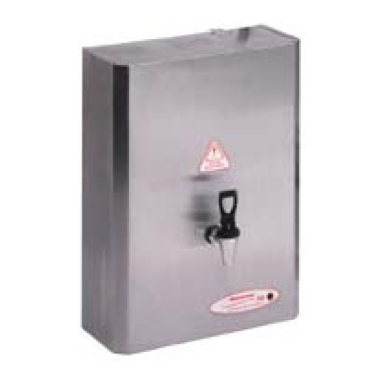
Trouble Shooting All Models Redring SB Professional On Wall Boiling Water Heater Models: 1070800E 2.5 ltr 1070810E 5 ltr 1070815E 7.5 ltr 1070820E 10 ltr 1070825E 15 ltr 1070830E 20 ltr 1070835E 25 ltr Page 1 of 8... - Page 2 Contents Subject Page General Product Operation..............2 Spares Diagram and List.................3 Unit Dimensions..................3 Problem Solving..................4 Tank Access....................5 Parts Replacement Guide...............5 - 6 Intentionally Blank..................7 AEP Address....................8 The General Operational Process 1. After fixing to wall and checking all connections, turn on power and water together.
- Page 3 Spare parts and diagrams for location and installation dimensions. Spare Parts 1311056 Tap Assembly Part No Description 1311082 Sensor (minimum water level) 1311010 Water Solenoid Valve 1311048 Probe (maximum water level) 1311044 Condenser Assembly Steam Vent Outlet Cold Water Inlet To Tank 1311043 Thermistor Steam Sensor Maximum Water Level...
-
Page 4: Problem Solving
Problem Solving Symtom Solution Unit filling to low level but not heating 1. Possible faulty PCB 2. Check Element 3. Check all wiring connections Unit not filling 1. Check top probe (No.11 page 3) and ensure that the probe is not in contact with tubing. Also check for scale build up. - Page 5 Tank access and replacing parts Task Operation Front cover removal 1. Turn power and water off 2. Drain unit via tap, be carefull of boiling water. 3. Remove the tap assy by unscrewing counter-clockwise 4. Undo self-tapping screws, 2 at top and 2 at bottom of case.
- Page 6 Tank access and replacing parts con’t. Task Operation Replace Thermistor Steam Sensor 1. Directions as above in Cover Removal. 2. Remove PCB cover plate. 3. Remove the thermistor. 4. The probe end of the thermistor pushes into the condensor tube so that the tip just covers the hole drilled in the condensor tube.
- Page 7 Notes Page 7 of 8...
- Page 8 Applied Energy Products Ltd, Morley Way, Peterborough. PE2 9JJ. England General enquiry +44 (0) 1733 456789 +44 (0) 1733 310606 Technical Hotline +44 (0) 8709 000430 +44 (0) 8709 000530 Sales/Spares +44 (0) 8709 000420 +44 (0) 8709 000520 Page 8 of 8...