Table of Contents
Advertisement
Advertisement
Table of Contents

Related Manuals for Precor move beyond S3.19


Summary of Contents for Precor move beyond S3.19
- Page 1 S3.19 Strength-Training Fitness Equipment Assembly and Maintenance Guide...
-
Page 3: Important Safety Instructions
You can find the serial number printed on • Use the equipment only for its intended purpose as a label affixed to the side of the S3.19. For Personal Safety During Assembly described in this manual. Do not use accessory... -
Page 4: Table Of Contents
S3.19 Assembly and Maintenance Guide Table of Contents Important Safety Instructions .................. 3 Personal Safety During Assembly ......................3 Obtaining Service ............................. 3 Before You Begin ....................... 5 Unpacking the Equipment ........................5 Optional Equipment ..........................5 Preparations ....................... 6 Required Tools ............................ -
Page 5: Before You Begin
S3.19 Assembly and Maintenance Guide Before You Begin Thank you for purchasing the S3.19. This unit is part of the Precor Strength line of quality strength training Hi/Lo Pulley machines which let you target specific muscle groups to Assembly S3.19 achieve better muscle tone and overall body conditioning. -
Page 6: Preparations
You must review and follow the instructions in this access. guide. If you do not assemble and use the S3.19 • Insert all fasteners in the same direction. For according to the following guidelines, you could void... -
Page 7: Assembly Instructions
S3.19 Assembly and Maintenance Guide Assembly Instructions Assembly of the S3.19 takes professional installers about 2½ hours to complete. If this is the first time you have assembled this type of equipment, plan on significantly more time. Professional installers are highly recommended! -
Page 8: Open The Box
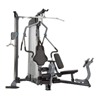
S3.19 Assembly and Maintenance Guide Open the Box Use wire tie cutters to open the boxes. The illustration shows how the S3.19 will look when you have completed its assembly. The callouts identify Lat Bar specific pieces. Important: Most fasteners are fitted to the frame or... -
Page 9: Assemble Main Structure
S3.19 Assembly and Maintenance Guide 1. Assemble Main Structure 2 - 4¾" bolts A. Attach the Main Base to the Rear Crossbar using 4 - washers two ¾-inch hex head bolts 2 - locknuts Rear Crossbar four flat washers two locknuts B. - Page 10 S3.19 Assembly and Maintenance Guide D. Disassemble and remove the top pulley and its fasteners on the Main Upright. Align Top Beam with E. Install the Top Beam on the Rear and Main uprights. Uprights. Note: If necessary, use a rubber mallet to align the 2 - 2¼"...
-
Page 11: Assemble Leg Extension
S3.19 Assembly and Maintenance Guide 2. Assemble Leg Extension A. Cut wire ties. B. Attach the Leg Extension to the Main Base using two ½-inch bolts two spring washers Wrench tighten using a box-end wrench. 2 - 2½” bolts 2 - spring washers... -
Page 12: Install Rollers And Seat Pads
S3.19 Assembly and Maintenance Guide 3. Install Rollers and Seat Pads 1 - ½" threaded shaft 2 - ½" zinc bolts A. Attach the top roller pads using 2 - zinc washers one ½-inch x 3½-inch threaded shaft two ½-inch zinc bolts two zinc flat washers Wrench tighten using the 5mm hex key. - Page 13 S3.19 Assembly and Maintenance Guide G. Attach the Seat Pad to the Seat Stem using four 1-inch zinc buttonhead bolts 3 - 1" zinc bolts two zinc flat washers 3 - zinc washers Wrench tighten using a 6mm hex key.
-
Page 14: Assemble Weight Stack
S3.19 Assembly and Maintenance Guide 4. Assemble Weight Stack Important: Obtain adult assistance before installing the Guide Rods and Weights. A. Place the Guide Rods into the two outside holes in the Main Base. CAUTION: The lubricant on the Guide Rods can stain clothes. - Page 15 S3.19 Assembly and Maintenance Guide D. Orient the hole in the Top Cap Weight with the curve in the weight plates. Place the Top Cap Weight onto the Guide Rods and slide the Selector Stem into the weight stack. E. Slide the Guide Rod Bracket onto the Guide Rods and secure it to the Upper Frame Crosspiece using two ¾-inch buttonhead bolts...
-
Page 16: Assemble Press Arm
S3.19 Assembly and Maintenance Guide 5. Assemble Press Arm Important: Obtain adult assistance to attach the Press 1 - ¾" threaded shaft Arm Assembly. 2 - " zinc buttonhead bolts 2 - zinc washers A. Attach the Press Arm Assembly, with the label facing out, to the Top Beam using one ¾-inch x 5¼-inch threaded shaft... - Page 17 S3.19 Assembly and Maintenance Guide B. Slide the Handlebars in place on the Press Arm. Handlebars curve inward. Review the illustration for correct handlebar placement. Pull the T-handle up and adjust the handlebars into a secure position. C. Attach the Row Handles using eight ¼...
-
Page 18: Install Hi/Lo Pulley Assembly
S3.19 Assembly and Maintenance Guide 6. Install Hi/Lo Pulley Assembly 2 - 4" bolts Note: Ask for assistance to move the Hi/Lo Pulley 1 - 2" bolt 4 - radius washers 1 - washer Assembly and align the mounting holes. -
Page 19: Install Lat Pulley Cable
S3.19 Assembly and Maintenance Guide 7. Install Lat Pulley Cable Pulley assemblies Note: All pulleys (except the floating pulleys) are Lat Pulley Cable 4½-inch Pulley installed in the frame assemblies. As you begin 130208 1 - bolt each new step, remove the fasteners and pulley. - Page 20 S3.19 Assembly and Maintenance Guide E. Feed the cable over the lower 3½-inch pulley located in the Press Arm assembly. Attach the pulley to the Press Arm assembly using Lat Bar Holder 2 - 2" bolts one 2-inch zinc hex head bolt...
-
Page 21: Install Leg Extension Cable
S3.19 Assembly and Maintenance Guide 8. Install Leg Extension Cable A. Remove the hex head bolt from the Gusset which is welded to the Base Frame. Place the end of the Multiplier Arm Leg Extension Cable 130210 on the bolt as shown. -
Page 22: Install Leg Press Option Cable Connection
S3.19 Assembly and Maintenance Guide 9. Install Leg Press Option Cable Connection A. Disassemble the 3½-inch pulley attached to the base frame bracket and feed the threaded end of the Leg Press Option Cable 130211 under the pulley. Reattach the pulley to its bracket using... -
Page 23: Install Mid Pulley Cable And Hi/Lo Pulley Connection
S3.19 Assembly and Maintenance Guide 10. Install Mid Pulley Cable and Hi/Lo Pulley Connection A. Disassemble the center pulley on the Main Upright and feed the threaded end of Mid Pulley Cable 130209 through the opening and over the 3½-inch pulley. - Page 24 D. Feed the threaded end of the cable over the top of the Mid-pulley Bracket’s 3½-inch pulley. Rest the cable on the floor. Mid- Important: Stand between the S3.19 and the Hi/Lo Pulley Pulley Assembly and review the cable alignment. Bracket...
- Page 25 S3.19 Assembly and Maintenance Guide E. Disassemble the Single Floating Pulley attached to the Leg Press Option Cable 130211 and feed the Mid Pulley Cable around the disassembled pulley. Reattach the pulley to the floating pulley housing using one 2-inch zinc hex head bolt...
- Page 26 S3.19 Assembly and Maintenance Guide J. Feed the threaded end of the cable beneath the 3½-inch pulley at the base of the Hi/Lo Pulley and reattach it using one 2-inch hex head bolt two flat washers one locknut Wrench tighten.
-
Page 27: Install Shrouds
S3.19 Assembly and Maintenance Guide 11. Install Shrouds 6 - 1¾" zinc buttonhead bolts Note: Read and follow the steps found in Cable 6 - black plastic washers Adjustments and Maintenance to lubricate the guide 6 - tapered spacers rods and make the appropriate cable adjustments prior to installing the Shrouds. -
Page 28: Attach Accessories
S3.19 Assembly and Maintenance Guide 12. Attach Accessories A. At the end of the Top Beam, attach the Lat Bar to the Lat Pulley Cable using a spring clip. Note: The two hooks at the end of the Top Beam can be used to store the Lat Bar when it’s not in... -
Page 29: Move The Hi/Lo Pulley
S3.19 Assembly and Maintenance Guide 13. Move the Hi/Lo Pulley A. To raise the Hi/Lo Pulley, simply push the Blue Handle up along the track. The Hi/Lo Pulley automatically locks into position. B. To lower the Hi/Lo Pulley, lift the Blue Handle up so it disengages from the track and then slowly lower the Hi/Lo Pulley. -
Page 30: Apply Weight Decals And Lubricant
C. Apply one tube of lubricant to each Guide Rod. CAUTION: The lubricant can stain clothes. Wear proper attire when lubricating the Guide Rods. This completes the assembly of your S3.19 Strength- Training Fitness Equipment. Before exercising on the S3.19, adjust the cable tension. Refer to Cable Adjustments and Maintenance. -
Page 31: Cable Adjustments And Maintenance
S3.19 Assembly and Maintenance Guide Cable Adjustments and Maintenance When the S3.19 is completely assembled, you need to check the cables for proper tension. Obvious signs that cable problems exist include: ✔ Top Cap Weight does not rest squarely on the top weight of the Weight Stack. -
Page 32: Cable Tension
S3.19 Assembly and Maintenance Guide 1. Cable Tension If you experience any cable problems, take the following steps to reduce tension on the cables: A. Remove the Weight Pin and set it aside. B. If the Leg Press is attached, place the Support Arm in the upright (non-extended) position. -
Page 33: Cable Adjustments
S3.19 Assembly and Maintenance Guide 2. Cable Adjustments You may need to adjust the cables after installation and Threads periodically thereafter. If the cables remain slack after you have followed the steps found in Cable Tension, perform the following: Jam Nut A. -
Page 34: Selector Stem Adjustments
S3.19 Assembly and Maintenance Guide 3. Selector Stem Adjustments If the Selector Stem consistently strikes the inside of the weight stack or it is misaligned with the Weight Stack hole, you can re-center the Selector Stem by taking the following steps: A. -
Page 35: Lubricate Guide Rods
B. Lubricate the Guide Rods every six months. need of service. The acrylic Shrouds on the S3.19 are easily scratched CAUTION: The lubricant can stain clothes. Wear or damaged through improper cleaning techniques. To You are responsible for the proper maintenance of the proper attire when lubricating the Guide Rods. -
Page 36: Limited Warranty Statement
90-day parts and labor limited For any product described above that fails to conform to its warranty, Precor will provide, at their option, one of warranty. All components that are not internally connected have 90-day parts only limited warranty. - Page 38 Please detach and mail in the warranty registration within ten days of purchase.
-
Page 40: Specifications
Precor is widely recognized for its innovative, award winning designs of exercise equipment. Precor aggressively seeks U.S. and foreign Registration Card 45623-102 patents for both the mechanical construction and the visual aspects of its product design. Any party contemplating the use of Precor’s Warranty Statement 36287-110 product designs is hereby forewarned that Precor considers the unauthorized appropriation of its proprietary rights to be a very serious matter.
Need help?
Do you have a question about the move beyond S3.19 and is the answer not in the manual?
Questions and answers