
Related Manuals for Friedrich ZQ08B10


Summary of Contents for Friedrich ZQ08B10
-
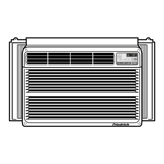
Page 1: Room Air Conditioner
Room Air Conditioner Service and Parts Manual ZQ08B10 ZQ10B10 CP08A 10 CP10A 10 CP12A 10 ZQ08/10;CP08/10/12 (06/05) -
Page 2: Table Of Contents
CONTENTS 1. PREFACE 3. TROUBLESHOOTING GUIDE 1.1 SAFETY PRECAUTIONS........2 3.1 OUTSIDE DIMENSIONS.......13 1.2 INSULATION RESISTANCE TEST ....2 3.2 PIPING SYSTEM...........14 1.3 SPECIFICATIONS...........3 3.3 TROUBLESHOOTING GUIDE .....15 1.4 FEATURES............4 4. SCHEMATIC DIAGRAM .....19 1.5 CONTROL LOCATIONS .........4 5. EXPLODED VIEW 2. DISASSEMBLY INSTRUCTIONS ........20 6. -
Page 3: Specifications
1.3 SPECIFICATIONS 1.3.1 F OR ZQ08B 10,ZQ10B 10,C P 08A 10,C P 10A 10,C P 12A 10 MODE L S ZQ08B 10 ZQ10B 10 C P 08A10 C P 10A10 C P 12A10 IT E MS P OWE R S UP P LY 1ø, 115V, 60HZ C OOLING C AP AC IT Y (B tu/h) -
Page 4: Features
1.4 FEATURES • Built-in adjustable Thermistor • Designed for COOLING ONLY. • Washable one-touch filter • Powerful and whispering cooling. • Compact size • Slide-in and slide-out chassis for the simple • Reliable and efficient rotary compressor is equipped. installation and service. •... - Page 5 DIS P L AY R E MOT E C ONT R OL Power Te mp Fan S peed T imer Mode Fig C Fig B Precaution: The Remote Control unit will not function properly if strong light strikes the sensor window of the air conditioner or if there are obstacles between the Remote Control unit and the air conditioner.
-
Page 6: Disassembly Instructions
2. DISASSEMBLY INSTRUCTIONS — Before the following disassembly, set POWER SWITCH to OFF and disconnect the power cord. 2.1 MECHANICAL PARTS 2.1.1 FRONT GRILLE 1. Open the lnlet grille downward and remove the air filter. 2. Remove the screw which fastens the front W ER grille.(See Figure 1) TI ME... -
Page 7: Air Handling Parts
2.2 AIR HANDLING PARTS 2.2.1 AIR GUIDE AND TURBO FAN 1. Remove the front grille. (Refer to section 2.1.1) 2. Remove the cabinet. (Refer to section 2.1.2) 3. Remove the control box. (Refer to section 2.1.3) 4. Remove the 4 screws which fasten the brace. 5. -
Page 8: Shroud
2.2.3 SHROUD 1. Remove the fan. (Refer to section 2.2.2) 2. Remove the shroud. (See Figure 8) 3. Re-install the components by referring to the removal procedure, above. Figure 8 2.3 ELECTRICAL PARTS 2.3.1 OVERLOAD PROTECTOR 1. Remove the cabinet. (Refer to section 2.1.2) 2. -
Page 9: Capacitor
2.3.3 CAPACITOR 1. Remove the control box. (Refer to section 2.1.3) 2. Open the top cover from the control box. (See Figure 11) 3. Pull out the capacitor from the control box. 4. Disconnect all the leads of capacitor terminals. 5. -
Page 10: Motor
2.3.5 MOTOR 1. Remove the cabinet. (Refer to section 2.1.2) 2. Remove the turbo fan. (Refer to section 2.2.1) 3. Remove the fan. (Refer to section 2.2.2) 4. Remove the 4 screws which fasten the motor to the air guide. (See Figure 13) 5. -
Page 11: Capillary Tube
2.4.3 CAPILLARY TUBE 3. Remove the capillary tube. 1. Remove the cabinet. (Refer to section 2.1.2) 4. Re-install the components by referring to notes. 2. After discharging the refrigerant completely, unbraze the interconnecting tube at the capillary tube.(See caution on previous page) NOTES —... - Page 12 Equipment needed: Vacuum pump, Charging cylinder, Manifold gauge, Brazing equipment. Pinch-off tool capable of making a vapor-proof seal, Leak detector, Tubing cutter, Hand Tools to remove components, Service valve. Figure 16B-Charging Figure 16A-Pulling Vacuum —12—...
-
Page 13: Outside Dimensions
3. TROUBLESHOOTING GUIDE 3.1 OUTSIDE DIMENSIONS unit: mm(inch) MODEL: ZQ08B10,CP08A10,ZQ10B10 490(19 / ) 8" 126.5(4 / ) 32" 510 20 29(1 / ) 32" COOL HEAT DEFROST ENERGY SAVER INDOOR DESIRED PURYFIER AUTO RESTART 18( / ) 32" MODEL:CP10A10,CP12A10 567(22 / ) 16"... -
Page 14: Piping System
3.2 PIPING SYSTEM CONDENSER COIL CAPILLARY TUBE MOTOR COMPRESSOR TURBO FAN EVAPORATOR COIL Figure 17 is a brief description of the important components and their function in what is called the refrigeration system. This will help you to understand the refrigeration cycle and the flow of the refrigerant in the cooling cycle. ROOM AIR CONITIONER CYCLE OF REFRIGERATION EVAPORATOR COILS... -
Page 15: Troubleshooting Guide
3.3 TROUBLESHOOTING GUIDE In general, possible trouble is classified in two kinds. The one is called Starting Failure which is caused from an electrical defect, and the other is ineffective Air Conditioning caused by a defect in the refrigeration circuit and improper application. Unit runs but poor cooling. - Page 16 Fails to Start Check power source. Check circuit breaker and fuse. Check control switch Gas leakage of feeler bulb setting. of thermostat Check control switch. Compressor only fails to Fan only fails to start. start. Improper wiring. Drop of power voltage. Improper thermostat setting.
- Page 17 COMPLAINT CAUSE REMEDY Fan motor will not run. No power Check voltage at outlet. Correct if none. Power supply cord Check voltage to rotary switch. If none, check power supply cord. Replace cord if circuit is open. Rotary switch Check switch continuity. Refer to wiring diagram for terminal identification.
- Page 18 COMPLAINT CAUSE REMEDY Compressor will not run, Thermostat Check the position of knob. If not at the coldest but fan motor runs. setting, advance the knob to this setting and restart unit. Check continuity of the thermostat. Replace thermostat if circuit is open. Capacitor (Discharge Check the capacitor.
-
Page 19: Schematic Diagram
4. SCHEMATIC DIAGRAM MODEL: CP08A10, CP10A10, CP12A10 MODEL: ZQ08B10,ZQ10B10 POWER INPUT CN-AC/DC CN-AC/DC CN-MOTOR BK(BR) WH(BL) (Plain) (Ribbed) GN/YL GN(GN/YL) ROTARY SWITCH MOTOR DC PCB ASSEMBLY CAPACITOR CN-TH1 MOTOR OR(BR) CAPACITOR POWER TRANS THERMISTOR OR(BR) CN-PWR FUSE Ribbed 250V/T2A COMP. -
Page 20: Exploded View
5. EXPLODED VIEW 731373 554031 149980 554030 148000 130910 W48602 346811 559011 359012 W48602 267110 352390-2 354210 249950 263230 352390-1 268712 268714 135500 W0CZZ 238310 349001 567502 349480 130410 264110 237200 554160 135312 147582-2 249950 550140 147581 552111 266003 352113 269310 352115 135500... -
Page 21: Replacement Parts List
6. REPLACEMENT PARTS LIST R: Service Parts N: Non Service Parts ZQ08B10 ZQ10B10 CP08A 10 CP10A 10 CP12A 10 ZQ08B10 Loc No FRIEDRICH Description 130410 67302924 BASE ASSEMBLY,SINGLE 130910 67303711 CABINET ASSEMBLY,SINGLE 135312 67306014 GRILLE ASSEMBLY,FRONT(SINGLE) 135313 67306109 GRILLE,INLET 135500... - Page 22 ZQ10B10 Loc No FRIEDRICH Description 130410 67302913 BASE ASSEMBLY,SINGLE 130910 67303711 CABINET ASSEMBLY,SINGLE 135312 67306014 GRILLE ASSEMBLY,FRONT(SINGLE) 135313 67306109 GRILLE,INLET 135500 67300311 COVER 147581 67306207 LOUVER,HORIZONTAL 147582-1 67306260 LOUVER,VERTICAL 147582-2 67306261 LOUVER,VERTICAL 148000 67303909 BRACE 149410 67304105 KNOB ASSEMBLY 149980...
- Page 23 CP08A10 Loc No FRIEDRICH Description 130410 67302913 BASE ASSEMBLY,SINGLE 130910 67303711 CABINET ASSEMBLY,SINGLE 135312 67306014 GRILLE ASSEMBLY,FRONT(SINGLE) 135313 67306109 GRILLE,INLET 135500 67300310 COVER 147581 67306207 LOUVER,HORIZONTAL 147582-1 67306260 LOUVER,VERTICAL 147582-2 67306261 LOUVER,VERTICAL 148000 67303909 BRACE 149980 67303110 SHROUD 152302 67304306...
- Page 24 CP10A10 Loc No FRIEDRICH Description 130410 67302923 BASE ASSEMBLY,SINGLE 130910 67303710 CABINET ASSEMBLY,SINGLE 135312 67306013 GRILLE ASSEMBLY,FRONT(SINGLE) 135313 67306108 GRILLE,INLET 135500 67300310 COVER 147581 67306206 LOUVER,HORIZONTAL 147582-1 67306258 LOUVER,VERTICAL 147582-2 67306259 LOUVER,VERTICAL 148000 67303908 BRACE 149980 67303113 SHROUD 152302 67304307...
- Page 25 CP12A10 Loc No FRIEDRICH Description 130410 67302922 BASE ASSEMBLY,SINGLE 130910 67303710 CABINET ASSEMBLY,SINGLE 135312 67306013 GRILLE ASSEMBLY,FRONT(SINGLE) 135313 67306108 GRILLE,INLET 135500 67300310 COVER 147581 67306206 LOUVER,HORIZONTAL 147582-1 67306258 LOUVER,VERTICAL 147582-2 67306259 LOUVER,VERTICAL 148000 67303908 BRACE 149980 67303112 SHROUD ASSEMBLY 152302...
- Page 26 MEMO —26—...
- Page 27 MEMO —27—...
- Page 28 Use Factory Certified Parts... FRIEDRICH AIR CONDITIONING CO. Visit our web site at www.friedrich.com Post Office Box 1540 • 4200 N. Pan Am Expressway • San Antonio, Texas 78295-1540 • (210) 357-4400 • FAX (210) 357-4490...
Need help?
Do you have a question about the ZQ08B10 and is the answer not in the manual?
Questions and answers