Table of Contents
Advertisement
Quick Links
Advertisement
Table of Contents
Troubleshooting

Subscribe to Our Youtube Channel
Related Manuals for Friedrich ZStar ZQ05A10B


Summary of Contents for Friedrich ZStar ZQ05A10B
- Page 1 Room Air Conditioner Service and Parts Manual ZStar ZQ05 / ZQ07 (4-04)
-
Page 2: Table Of Contents
CONTENTS 1. PREFACE ..............................3 1.1 FEATURES..............................3 1.2 SPECIFICATIONS ............................3 1.3 LOCATIONS OF CONTROLS ........................4 1.4 SAFETY PRECAUTIONS ..........................4 1.5 INSULATION RESISTANCE TEST ........................4 2. DISASSEMBLY INSTRUCTIONS ....................5 2.1 MECHANICAL PARTS ..........................5 2.1.1 FRONT GRILLE ............................5 2.1.2 CABINET..............................5 2.1.3 CONTROL BOARD ..........................5 2.2 AIR HANDLING PARTS ..........................6 2.2.1 AIR GUIDE UPPER ..........................6 2.2.2 ORIFICE, TURBO FAN AND FAN ......................6... -
Page 3: Preface
1. PREFACE This service manual provides various service information, including the mechanical and electrical parts, etc. This room air conditioner was manufactured and assembled under a strict quality control system. The refrigerant is charged at the factory. Be sure to read the safety precautions prior to servicing the unit. 1.1 FEATURES •... -
Page 4: Locations Of Controls
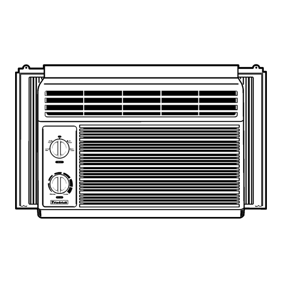
1.3 LOCATIONS OF CONTROLS : Turns air conditioner off. Operation Hi Fan : High speed fan operation without cooling. Cool Lo Fan : Low speed fan operation without cooling. Cool Hi Cool : Cooling with high speed fan operation. Mode Lo Cool : Cooling with low speed fan operation. -
Page 5: Disassembly Instructions
2. DISASSEMBLY INSTRUCTIONS 2.1 MECHANICAL PARTS 2.1.1 FRONT GRILLE Figure 1 1. Disconnect the unit from source of power. 2. Remove the two knobs by pulling them off. Using a screwdriver, remove the screw that secures the front grille to control board. (See Figure 1) 3. -
Page 6: Air Handling Parts
2.2 AIR HANDLING PARTS Figure 6 2.2.1 AIR GUIDE UPPER 1. Disconnect the unit from the power source. 2. Remove the front grille. (Refer to Section 2.1.1) 3. Remove the cabinet. (Refer to Section 2.1.2) 4. Remove the control board. (Refer to Section 2.1.3) 5. -
Page 7: Motor
2.2.3 MOTOR Figure 10 1. Disconnect the unit from the power source. 2. Remove the front grille. (Refer to Section 2.1.1) 3. Remove the cabinet. (Refer to Section 2.1.2) 4. Remove the control board. (Refer to Section 2.1.3) 5. Remove the air guide upper. (Refer to Section 2.2.1) 6. -
Page 8: Compressor
2.3.2 COMPRESSOR Figure 14 1. Remove the front grille and cabinet. (Refer to Section 2.1) 2. Discharge the refrigerant by using a refrigerant recovery system. 3. Remove the overload protector. (Refer to Section 2.3.1) 4. After discharging the unit completely, unbrace the suction and discharge pipes at the compressor connections. -
Page 9: Power Cord
2.3.6 POWER CORD Figure 18 1. Disconnect the unit from source of power. 2. Remove the front grille. (Refer to Section 2.1.1) 3. Remove the cabinet. (Refer to Section 2.1.2) 4. Remove a screw that secures control board to base pan. (Refer to Section 2.1.3) 5. -
Page 10: Evaporator
2.4.2 EVAPORATOR wise. This will keep oil from foaming and being drawn into the vacuum pump. 1. Remove the cabinet. 2. Discharge the refrigerant by using a refrigerant 6-3. Operate the vacuum pump for 20 to 30 min- recovery system. utes, until 600 micron vacuum is obtained. - Page 11 Equipment needed: Vacuum pump, charging cylinder, manifold gauge, brazing equipment, pinch-off tool capable of making a vapor proof seal, leak detector, tubing cutter, hand tools to remove components and service valve. COMPOUND GAUGE MANIFOLD GAUGE CONDENSER SEE INSETS (HIGH PRESSURE SIDE) BELOW COMPRESSOR EVAPORATOR...
-
Page 12: Installation
3. INSTALLATION This air conditioner is designed with a button-down chassis so it can be easily installed in a window. 3.1 SELECT THE BEST LOCATION 1. To prevent vibration and noise, make sure the unit is installed securely and firmly. 2. -
Page 13: Before Installation
Installation HARDWARE TYPE A: 11EA TYPE B: 4EA TYPE C: 3EA (SHORT SCREW) (WOOD SCREW) (L BACKET) TYPE D: 1EA TYPE E: 1EA TYPE F: 2EA (SEAL STRIP) (SASH SEAL) (GUIDE PANEL) (Adhesive backed) (Not adhesive backed) 3.2.2 BEFORE INSTALLATION 1. - Page 14 3. INSTALL THE AIR CONDITIONER IN THE WINDOW INNER SILL a. Carefully lift the air conditioner and slide it into the TYPE A OUTER SILL INSIDE open window. Make sure the bottom guide of the air CENTER LINE conditioner drops into the notches of the L bracket.
-
Page 15: Electrical Data
REMOVAL FROM WINDOW Turn the air conditioner off, disconnect the power cord, remove the L bracket and the screws installed through the top and bot- tom of the guide panels, and save for reinstallation later. Close the guide panels. Keeping a firm grip on the air conditioner, raise the sash, and carefully tilt the air conditioner backward, draining any condensate water. -
Page 16: Piping System
4.2 PIPING SYSTEM CONDENSER COILS MOTOR CAPILLARY TUBE TURBO FAN EVAPORATOR COILS Following is a brief description of the important components and their function in what is called the refrigeration system. Reference should be made to Figure 32 to follow the refrigerating cycle and the flow of the refrigerant in the cooling cycle. -
Page 17: Troubleshooting Guide
4.3 TROUBLESHOOTING GUIDE In general, possible trouble is classified in two kinds. The one is called Starting Failure which is caused by an electrical defect. The other is Ineffective Air Con- ditioning caused by a defect in the refrigeration circuit and improper application. Unit is running but cooling is ineffective. - Page 18 Fails to Start Check of circuit breaker Check of power source. and fuse. Check of control switch Gas leakage of feeler setting. bulb of thermostat. Check control switch. Compressor fails only to Fan only fails to start. start. Improper wiring. Improper thermostat Drop of power voltage.
- Page 19 ROOM AIR CONDITIONER VOLTAGE LIMITS NAME PLATE RATING MINIMUM MAXIMUM 115V ± 10% 103.5V 126.5V COMPLAINT CAUSE REMEDY Fan motor will not run. No power Check voltage at outlet. Correct if none. Power supply cord Check voltage to rotary switch. If none, check power supply cord.
- Page 20 COMPLAINT CAUSE REMEDY Fan motor noise. If cracked, out of balance, or partially missing, replace it. Blower If cracked, out of balance, or partially missing, replace it. Loose set screw Tighten it. Worn bearings If knocking sounds continue when running or loose, replace the motor.
- Page 21 COMPLAINT CAUSE REMEDY Compressor cycles on Fan motor If not running, determine the cause. Replace if overload. required. Condenser air flow Remove the cabinet, inspect the interior surface restriction of the condenser. If restricted, clean carefully with a vacuum cleaner (do not damage fins) or brush.
-
Page 22: Circuit Diagram
5. CIRCUIT DIAGRAM POWER INPUT BK(BR) WH(BL) (Plain) (Ribbed) ROTARY SWITCH GN(GN/YL) MOTOR OR(BR) CAPACITOR OR(BR) COMP. THERMOSTAT SYNC. M. 3854AR2330A WIRING DIAGRAM ROCKER SWITCH PART NO. LOCATION Q'TY DESCRIPTION ZQ05A10B ZQ07A10B PER SET 2H00677P POWER CORD ASSY FAN MOTOR 4681A10012L 4681A10002K COMPRESSOR... -
Page 23: Exploded View
6. EXPLODED VIEW 130910 559011 W48602 554030 149980 349480 352380 135312 147581 149410 359012 346811 147582-1 W48602 352390 147582-2 354210 130410 152302 135313 249950 266003 135500 264110 352111 352115 567502 352113 269310 554160 35211A W0CZZ 550140 —23—... -
Page 24: Service Parts List
7. SERVICE PARTS LIST • ZQ05A10B, ZQ07A10B PART NO FRIEDRICH PART NO. LOCATION NO DESCRIPTION Remark ZQ05A10B ZQ07A10B ZQ05A10B ZQ07A10B 130410 BASE ASSY, SINGLE 3041A10011F 67302906 130910 CABINET ASSY, SINGLE 3091A10020A 67303704 135312 GRILLE ASSY, FRONT(SINGLE) 3531AR1644B 67306003 135313 GRILLE ASSY, INLET... - Page 25 MEMO —25—...
- Page 26 MEMO —26—...
- Page 27 Use Factory Certified Parts... FRIEDRICH AIR CONDITIONING CO. Visit our web site at www.friedrich.com Post Office Box 1540 • 4200 N. Pan Am Expressway • San Antonio, Texas 78295-1540 • (210) 357-4400 • FAX (210) 357-4480 P/NO.:3828A20038T Printed in the U.S.A...
Need help?
Do you have a question about the ZStar ZQ05A10B and is the answer not in the manual?
Questions and answers