Table of Contents
Advertisement
Statement:
This manual is the intellectual property of Foxconn Inc. Although the
information in this manual may be changed or modified at any time,
Foxconn does not obligate itself to inform the user of these changes.
Trademark:
All trademarks are the property of their respective owners.
Version:
User's Manual V1.0 for 6100M2MA series motherboard.
Symbol description:
Note: refers to important information that can help you to use motherboard
better.
Attention: indicates that it may damage hardware or cause data loss,
and tells you how to avoid such problems.
Warning: means that a potential risk of property damage or physical
injury exists.
More information:
If you want more information about our products, please visit the following
website: http://www.foxconnchannel.com
Advertisement
Table of Contents

Related Manuals for Foxconn 6100M2MA series


Summary of Contents for Foxconn 6100M2MA series
-
Page 1: More Information
This manual is the intellectual property of Foxconn Inc. Although the information in this manual may be changed or modified at any time, Foxconn does not obligate itself to inform the user of these changes. Trademark: All trademarks are the property of their respective owners. -
Page 2: Declaration Of Conformity
Declaration of conformity HON HAI PRECISION INDUSTRY COMPANY LTD 66 , CHUNG SHAN RD., TU-CHENG INDUSTRIAL DISTRICT, TAIPEI HSIEN, TAIWAN, R.O.C. declares that the product Motherboard 6100M2MA is in conformity with (reference to the specification under which conformity is declared in accordance with 89/336 EEC-EMC Directive) þ... - Page 3 Declaration of conformity Trade Name: WinFast Model Name: 6100M2MA Responsible Party: PCE Industry Inc. Address: 458 E. Lambert Rd. Fullerton, CA 92835 Telephone: 714-738-8868 Facsimile: 714-738-8838 Equipment Classification: FCC Class B Subassembly Type of Product: Motherboard Manufacturer: HON HAI PRECISION INDUSTRY COMPANY LTD Address: 66 , CHUNG SHAN RD., TU-CHENG...
-
Page 4: Table Of Contents
Table of Contents Chapter Product Introduction Main Features .................... 2 Motherboard Layout ................... 5 Rear Panel Connectors ................6 Chapter Installation Instructions CPU ......................9 Memory ....................13 Power Supply ..................15 Other Connectors ..................16 Expansion Slots ..................21 Jumpers .................... - Page 5 Table of Contents Chapter Driver CD Introduction Utility CD content ..................48 Start to install drivers ................49 Chapter Directions for Bundled Software Tiger ONE ....................51 Fox LiveUpdate ..................57...
- Page 6 Attention: 1. Attach the CPU and heatsink using silica gel to ensure full contact. 2. It is suggested to select high-quality, certified fans in order to avoid damage to the motherboard and CPU due to high temperature. 3. Never turn on the machine if the CPU fan is not properly installed. 4.
- Page 7 This manual is suitable for motherboard of 6100M2MAseries. Each motherboard is carefully designed for the PC user who wants diverse features. -L with onboard 10/100M LAN(Default is elliptical) -K with onboard Gigabit LAN -6 with 6-channel audio(Default is elliptical) -8 with 8-channel audio -E with 1394 Connector -S with SATA Connector -R with RAID function...
- Page 8 Chapter Thank you for buying WinFast 6100M2MA series motherboard. This series of motherboard is one of our new products, and offers superior performance, reliability and quality, at a rea- sonable price. This motherboard adopts the advanced NVIDIA ® GeForce 6100+ nForce...
-
Page 9: Chapter 1 Product Introduction
Chapter 1 Product Introduction Main Features Size: mATX form factor of 9.6” x 9.6” Microprocessor: l Supports AMD socket AM2 for Sempron , Athlon 64, Athlon 64 FX,Athlon 64 x2 Dual-Core processors l Supports HyperTransport Technology Chipset: NVIDIA ® : GeForce 6100+ nForce 430/410 System Memory... - Page 10 Chapter 1 Product Introduction Onboard 1394(optional) Supports hot-plug Two 1394 ports with rate of transmission at 400Mbps Self-configured addressing Onboard LAN (-L/-K) Supports10/100/1000(-K) Mbps Ethernet LAN interface built-in on board Onboard Audio (-6) (optional) AC’ 97 2.3 Specification Compliant Supports S/PDIF output Onboard Line-in jack, Line-out jack, Microphone jack Supports 6-channel audio (setting via software) Onboard Audio (-8) (optional)
- Page 11 Chapter 1 Product Introduction PCI Express x16 graphics support Supports 4GB/sec(8 GB/sec concurrent) bandwidth Low power consumption and power management features PCI Express x1 Support Supports 250 MB/sec (500 MB/sec concurrent) bandwidth Low power consumption and power management features Advanced Features PCI 2.3 Specification Compliant Supports PC Health function (capable of monitoring system voltage, CPU/ system temperature, and fan speed)
-
Page 12: Motherboard Layout
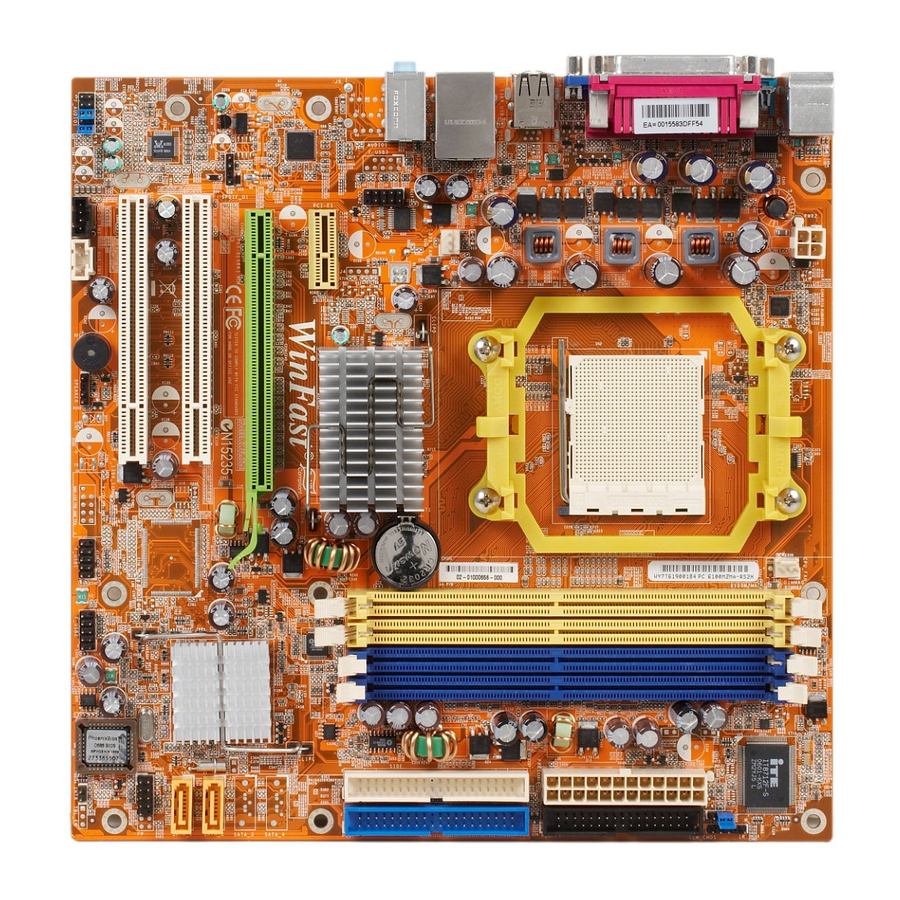
Chapter 1 Product Introduction Motherboard Layout 1. Front Audio Connector 14.Clear CMOS Jumper 2. CD_IN Connector 15.ATX Power Connector 16. DDR2 DIMM Slots 3. AUX_IN Connector (optional) 17. CPU Fan Connector 4. Speaker Connector(optional) 5. Front 1394 Connector (optional) 18. CPU Socket 6. -
Page 13: Rear Panel Connectors
Chapter 1 Product Introduction Rear Panel Connectors This motherboard provides the following ports as below: LAN Port Parallel Port (Printer Port) PS/2 Mouse Port PS/2 Keyboard Port VGA Port USB 2.0 Port COM1 1394 Port (optional) Line-out Line-in Rear LFE/CEN Side Microphone Line-in jack, Line-out jack, Microphone jack(for -6 models) - Page 14 Chapter 1 Product Introduction Chapter This chapter introduces the hardware installation process, including the installation of the CPU and memory. It also addresses the connection of your power supply, connection of hard drive and floppy drive data cables, and setting up various other feature of the motherboard.
- Page 15 Chapter 2 Installation Instructions Notes: Take note of the following precautions before you install components or change settings. 1. Use a grounded wrist strap or touch a safely grounded object, such as an attached power supply, before handling components to avoid damaging them due to static electricity.
-
Page 16: Chapter Installation Instructions Cpu
Chapter 2 Installation Instructions This motherboard supports AMD socket AM2 for Sempron , Athlon 64, Athlon 64 FX,Athlon 64 x2 Dual-Core processors and HyperTransport Technology. Attention: The CPU pins must be properly aligned with the holes in the socket, otherwise the CPU may be damaged. For the detailed CPU vendor list qualified on this motherboard, please visit the website: http://www.foxconnchannel.com... - Page 17 Chapter 2 Installation Instructions Installation of CPU Fan New technology allows processors to run at higher and higher frequencies. To avoid p rob lems arisin g f r om hig h -sp eed op erat io n , f o r exam p le, overheating, you need to install the proper fan.
- Page 18 Chapter 2 Installation Instructions 3. Place the cooling set onto the re- 4. Align the other end of the reten- tention mechanism. Attach one end tion bracket to fasten the cooling of the retention bracket to retention set on the top of the retention mechanism.
- Page 19 Chapter 2 Installation Instructions 6. Connect the fan’s power cable to the appropriate 3-pin terminal on the motherboard.
-
Page 20: Memory
Chapter 2 Installation Instructions Memory This motherboard includes four 240-pin slots with 533/667/800 MHz Dual Chan- nel DDR2 DRAM interface. You must install at least one menory module to ensure normal operation. For the lastest memory modules support list, please visit the website: http://www.foxconnchannel.com Installation of DDR2 Memory 1. - Page 21 Chapter 2 Installation Instructions Recommended Memory Configurations The following table list is the recommended memory configurations. Please in- stall the memory according to the list. Mode DIMMA0 DIMMB0 DIMMA1 DIMMB1 Populated Signal-channel Populated Populated Populated Populated Populated Dual-channel Populated Populated Populated Populated Populated...
-
Page 22: Power Supply
Chapter 2 Installation Instructions Power Supply This motherboard uses an ATX power supply. In order to avoid damaging any devices, make sure that they have been installed properly prior to connecting the power supply. ATX Power Connector: PWR1 +5 V PSON RSVD +3.3V... -
Page 23: Other Connectors
Chapter 2 Installation Instructions Other Connectors This motherboard includes interfaces for FLOPPY, IDE devices, SATA IIdevices, USB devices, 1394 devices, IR module, CPU fan, system fan, and others. FLOPPY This motherboard includes a standard FLOPPY interface, supporting 360 K, 720 K, 1.2 M, 1.44 M, and 2.88 M FDDs. - Page 24 Chapter 2 Installation Instructions Hard Disk LED Connector (HDD_LED) Attach the connector to the HDD_LED on the front panel of the case; the LED will flash while the HDD is in operation. Reset Switch (RESET) Attach the connector to the Reset switch on the front panel of the case; the system will restart when the switch is pressed.
- Page 25 Chapter 2 Installation Instructions Audio Connectors: CD_IN, AUX_IN(optional) CD_IN, AUX_IN is Sony standard CD audio connectors, to receive audio input from the CD-ROM, attach its audio connector to the CD_IN/AUX_IN audio con- nectors on the motherboard. CD_R AUX_R CD_IN AUX_IN CD_L AUX_L IrDA Connector: IR...
- Page 26 Chapter 2 Installation Instructions Front Audio Connector: F_AUDIO1 (for -6 models) The audio port includes two parts – the Front MIC_IN MIC_GND Audio and Rear Audio. Their priority is se- +5VAC MIC_PWR quenced from high to low (Front Audio to Rear AUD_RET_R AUD_OUT_R Audio).
- Page 27 Chapter 2 Installation Instructions Addtional COM Connector: COM2 RLSD SOUT DTR# This motherboard provides an additional DSR# serial COM connector for your machine. RTS# CTS# Connect one side of a switching cable to the Empty connector, then attach the serial COM device COM2 to the other side of the cable.
-
Page 28: Expansion Slots
Chapter 2 Installation Instructions Expansion Slots This motherboard includes two 32-bit Master PCI bus slots,one PCI Express x1 slot and onePCI Express x16 Graphics slot. PCI Slots The expansion cards can be installed in the two PCI slots. W hen you install or remove such cards, please make sure that the power plug has been unplugged from the power supply. - Page 29 Chapter 2 Installation Instructions Installing an expansion card 1. Before installing the expansion card, please make sure that the power sup- ply is switched off or the power cord is unplugged. Please read the docu- mentation that came with it and make the necessary hardware settings for the card.
-
Page 30: Jumpers
Chapter 2 Installation Instructions Jumpers Users can change the jumper settings on this motherboard if necessary. This section explains how to use the various functions of this motherboard by chang- ing the jumper settings. Users should read the following contents carefully prior to modifying any jumper settings. -
Page 31: Powering Off The Computer
Chapter 2 Installation Instructions Starting up for the first time 1. After making all the connections, replace the system case cover. 2. Make sure that all switches are turned off. 3. Turn on the devices in the following order. Monitor External SCSI devices (starting with the last device on the chain) System power 4. - Page 32 Chapter This chapter tells how to change system settings through the BIOS Setup menus. Detailed descriptions of the BIOS param- eters are also provided. You have to run the Setup Program when the following cases occur: 1. An error message appears on the screen during the system POST process.
-
Page 33: Enter Bios Setup
Chapter 3 BIOS Description Enter BIOS Setup The BIOS is the communication bridge between hardware and software, correctly setting up the BIOS parameters is critical to maintain optimal system performance. Power on the computer, when the following message briefly appears at the bottom of the screen during the POST (Power On Self Test), press the <Del>... - Page 34 Chapter 3 BIOS Description Advanced Chipset Features The values for the chipset can be changed through this menu, and the sys- tem performance can be optimized. Integrated Peripherals All onboard peripherals can be set up through this menu. Power Management Setup All the items of Green function features can be set up through this menu.
-
Page 35: Standard Cmos Features
Chapter 3 BIOS Description Standard CMOS Features This sub-menu is used to set up the standard CMOS features, such as the date, time, HDD model and so on. Use the arrow keys select the item to set up, and then use the <PgUp> or <PgDn> key to choose the setting values. Standard CMOS Features Menu Date This option allows you to set the desired date (usually as the current date) - Page 36 Chapter 3 BIOS Description Award (Phoenix) BIOS can support 4 HDD modes: CHS, LBA and Large or Auto mode. For HDD<528MB For HDD>528MB & supporting LBA (Logical Block Addressing) Large For HDD>528MB but not supporting LBA Auto Recommended mode Drive A This option allows you to select the kind of FDD to be installed, including [None], [360K, 5.25in], [1.2M, 5.25in], [720K, 3.5in], [1.44M, 3.5in] and [2.88 M, 3.5in].
-
Page 37: Advanced Bios Features
Chapter 3 BIOS Description Advanced BIOS Features Advanced BIOS Features Menu vRemovable Device Priority This option is used to remove the priority for removable device startup. After pressing <Enter>, you can remove the removable device using the <PageUp>/ <PageDn> or Up/ Down arrow keys, and change the removable device pri- ority using <+>... - Page 38 Chapter 3 BIOS Description vCPU Internal Cache This option is used to turn on or off the CPU L1 and L2 cache. vExternal Cache This option is used to turn on or off the CPU external cache. The available setting values are: Disabled and Enabled. Leave this item at the default value for better performance.
- Page 39 Chapter 3 BIOS Description vAPIC Mode This option is used to enable or disable APIC mode. vMPS Version Control For OS This option is used to set up the version of MPS Table used in NT4.0 OS. vOS Select For DRAM > 64MB This option is only required if you have installed more than 64 MB of memory and you are running the OS/2 operating system.
-
Page 40: Advanced Chipset Features
Chapter 3 BIOS Description Advanced Chipset Features Advanced Chipset Features Menu vFrame Buffer Size This item is used to set the VGA frame buffer size. Note: This function does not work when the external display card is used. vK8<->NB/NB-->SB/NB<--SB HT Speed These options are used to set the bandspeed of the link’s transmitter of K8 <->NB/NB-->SB/NB<--SB . - Page 41 Chapter 3 BIOS Description DRAM Configuration Menu vTime Mode This item is used to set timing mode. vMemory clock Value or Limit This option is used to set memory clock value or limit. vDQS Timing Training Control This option controls the DQS timing training . vCKE base Power down mode This option is used to set the CKE base Power dowm mode.
-
Page 42: Integrated Peripherals
Chapter 3 BIOS Description Integrated Peripherals Integrated Peripherals Menu vIDE Function Setup Press Enter to set the items about IDE Function. vRAID Config Press <Enter> to set the items of Raid configuration. vOnboard Device Press <Enter> to set the items of onboard device. vIDE HDD Block Mode This option is used to set whether the IDE HDD Block Mode is allowed. - Page 43 Chapter 3 BIOS Description vOnboard Parallel Port This option is used to assign the I/O address and interrupt request (IRQ) for onboard parallel port controller. The setting values include: Disabled, 378/ IRQ7, 278/IRQ5 and 3BC/IRQ7. vParallel Port Mode Select an address and corresponding interrupt for the onboard parallel port. The setting values include SPP, EPP, ECP, ECP+EPP.
- Page 44 Chapter 3 BIOS Description IDE Function Menu vOnChip IDE Channel 0/1 This option is used to set the onchip IDE channel 0/1. The available setting are: Disabled and Enabled. vIDE Primary/Secondary Master/Slave PIO These four items let you assign which kind of PIO (Programmer Input/Output) is used by IDE devices.
- Page 45 Chapter 3 BIOS Description RAID Config Menu RAID Enable This option is used to disable or enable the RAID function. W hen enabled, the following grayed items will be activated. vSATA 1/2 Primary/Secondary RAID These feature allow users to enable or disable the RAID function for each SATA hard disk drive.
- Page 46 Chapter 3 BIOS Description Onboard Device Setup vOnchip USB This option is used to set whether the USB Controller is enabled. vUSB Memory Type This option is used to set the USB Memory type. vUSB Keyboard Support This option is used to set whether the USB keyboard controller is enabled in a legacy operating system (such as DOS).
-
Page 47: Power Management Setup
Chapter 3 BIOS Description Power Management Setup Power Management Setup Menu vACPI function ACPI stands for “Advanced Configuration and Power Interface”. ACPI is a standard that defines power and configuration management interfaces be- tween an operating system and the BIOS. In other words, it is a standard that describes how computer components work together to manage system hardware. - Page 48 Chapter 3 BIOS Description vHDD Power Down This option is used to turn off hard disk power if the hard disk is idle for a given period of time. The setting values are Disabled and 1Min-15Min. vHDD Down In Suspend This option is used to define the continuous HDD idle time before the HDD enters power saving mode.
-
Page 49: Pnp/Pci Configurations
Chapter 3 BIOS Description PnP/PCI Configurations PnP/PCI Configurations Menu vInit Display First This item is used to set which display device will be used first when your PC starts up. vReset Configuration Data This option is used to set whether the system is permitted to automatically distribute IRQ DMA and I/O addresses each time the machine is turned on. -
Page 50: Pc Health Status
Chapter 3 BIOS Description PC Health Status PC Health Status Menu vShutdown Temperature This option is used to set the system temperature upper limit. W hen the temperature exceeds the setting value, the motherboard will automatically cut off power to the computer. vCPU Vcore, +3.3V, +5V, +12V, +5VSB, Voltage Battery, Current CPU Temperature, Current SYS Temperature, CPU Fan Speed, System Fan Speed These items display the current status of all the monitored hardware device/... -
Page 51: Frequency/Voltage Control
Chapter 3 BIOS Description Frequency/Voltage Control Frequency/Voltage Control menu vVDIMM Voltage Select This option is used to select the VDIMM voltage. v1.2V Core Voltage Select This option is used to select the 1.2V Core voltage. vVcore Voltage Select This option is used to select the Vcore voltage. -
Page 52: Load Fail-Safe Defaults
Chapter 3 BIOS Description Load Fail-Safe Defaults Select this option and press <Enter>, it will pop up a dialogue box to allow you to install fail-safe defaults for all appropriate items in the Setup Utility. Select <Y> and press <Enter> to load the defaults. Select <N> and press <Enter> to not load. -
Page 53: Save & Exit Setup
Chapter 3 BIOS Description Under the menu “Advanced BIOS Features Setup”, if you select “System” in Security Option, the screen will prompt you to enter password once the system is started or you want to enter CMOS setting program. If the password is wrong, it will refuse you to continue. - Page 54 Chapter The utility CD that came with the motherboard contains useful software and several utility drivers that enhance the mother- board features. This chapter includes the following information: Utility CD content Installing drivers Installing Utilities...
-
Page 55: Utility Cd Content
Chapter 4 Driver CD Introduction Utility CD content This motherboard comes with one Utility CD. To begin using the CD, simply insert the CD into your CD-ROM driver. The CD will automatically display the main menu screen. 1. Install Driver Using this option to install all the drivers for your motherboard. -
Page 56: Start To Install Drivers
Chapter 4 Driver CD Introduction Start to install drivers There are two ways to install drivers, manual or automatic. Click the drivers that “ you want to install and begin the setup steps by manual. Or you just click Click Setup” button to install the drivers by auto after install intel Chipset Drvier. Install by manual Ins tall by auto- matic... - Page 57 Chapter 4 Driver CD Introduction Chapter This chapter will introduce how to use attached software. This chapter provides the following information: TIGER ONE Fox LiveUpdate...
-
Page 58: Directions For Bundled Software
Chapter 5 Directions for Bundled Software TIGER ONE TIGER ONE is a powerful utility for easily modifying system settings. It also allows users to monitor various temperature values, voltage values, frequency and fan speed at any time. With TIGER ONE, you can -Modify system performance settings, such as bus speeds, CPU voltages, fan speed, and other system performance options that are supported by the BIOS... - Page 59 Click this button to configurate the parameters for the program. It determines which items will be shown in shorten mode. Homepage Click this button to visit Foxconn motherboard website. 2. CPU Page - CPU Control This page lets you select and run the Figer ONE developed benchmarks to determine the current performance level of the system.
- Page 60 Chapter 5 Directions for Bundled Software Go to CPU page Close this page Ajust by manual Reset the Apply the changes changes Select the different benchmarks 3. Freq. Page - Frequency Control This page lets you set memory and PCI Express frequency by manual. Go to Freq.
- Page 61 Chapter 5 Directions for Bundled Software 4.1 Limit Setting - CPU Temp. This page lets you to set CPU high limit temperature and enable the alert function. Show current CPU Go to Adjust page temperature value Enable alert function when the CPU temperature is higher than high limit value Show current high...
- Page 62 Chapter 5 Directions for Bundled Software 4.3 Limit Setting - CPU Fan This page lets you to set CPU fan low limit rpm and enable the alert function. Show current CPU fan rpm value Enable alert function when the CPU fan rev is lower than low limit rpm value Show current low limit...
- Page 63 Chapter 5 Directions for Bundled Software 5. Fan Page - Fan Control This page lets you enable smart Fan function or set fan speed by manual. Go to Fan page Enable or disable smart fan function Set fan speed by dragging the lever Reset the changes Apply the changes...
-
Page 64: Fox Liveupdate
Chapter 5 Directions for Bundled Software Fox LiveUpdate Fox LiveUpdate is a useful utility for backuping and updating the system BIOS, drivers and utilities by local or online. Supported Operating Systems: -W indows 2000 -Windows XP (32-bit and 64-bit) Windows 2003 (32-bit and 64-bit) Using Fox LiveUpdate: 1.1 Local Update - BIOS Info. - Page 65 Chapter 5 Directions for Bundled Software 1.2 Local Update - Backup This page lets you backup your system BIOS. Click “Backup”, then give a name. Click “Save” to finish the backup operation. Key in a BIOS name Click here 1.3 Local Update - Update This page lets you update your system BIOS from Internet.
- Page 66 Chapter 5 Directions for Bundled Software 2.1 Online Update - Update BIOS This page lets you update your system BIOS from Internet. Click “start”, it will search the new BIOS from Internet. Then follow the wizard to finish the update operation.
- Page 67 Chapter 5 Directions for Bundled Software 2.2 Online Update - Update Driver This page lets you update your system drivers from Internet. Click “start”, it will search the new drivers from Internet. Then follow the wizard to finish the update operation.
- Page 68 Chapter 5 Directions for Bundled Software 2.3 Online Update - Update Utility This page lets you update utilities from Internet. Click “start”, it will search the new utilities from Internet. Then follow the wizard to finish the update operation. Click here Current information Search new utilities from Internet...
- Page 69 Chapter 5 Directions for Bundled Software 3.1 Configure - option This page lets you set auto search options. After your setting, the utility will start searching and related information will show on the task bar. Click here Set auto search options Select search which kind of versions...
- Page 70 Chapter 5 Directions for Bundled Software 3.2 Configure - System This page lets you set the backup BIOS location and change different skin of the utility. Click here Set the location of download files or auto backup BIOS Select different skin of the software Reset to default value Determine if the Fox LiveUpdate...
Need help?
Do you have a question about the 6100M2MA series and is the answer not in the manual?
Questions and answers