Table of Contents
Advertisement
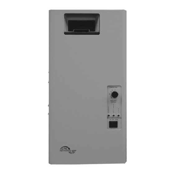
6000 Series
Electronic Steam Humidifiers
Installation
Operation
Service
OWNER'S MANUAL
The 6000 Series Humidifiers represent that
latest in humidification technology. Please read
these instructions carefully for trouble free
operation and to get the most out of your
purchase.
For further information concerning
this product, contact your local Herrmidifier
representative.
Advertisement
Table of Contents

Related Manuals for Herrmidifier 6000 Series


Summary of Contents for Herrmidifier 6000 Series
- Page 1 Electronic Steam Humidifiers Installation Operation Service OWNER’S MANUAL The 6000 Series Humidifiers represent that latest in humidification technology. Please read these instructions carefully for trouble free operation and to get the most out of your purchase. For further information concerning this product, contact your local Herrmidifier representative.
-
Page 2: Table Of Contents
TABLE OF CONTENTS TABLE OF CONTENTS..............................3 SECTION I WARRANTY..............................3 Warranty ..................................... 3 SECTION II UNIT OPERATION Basic Operation ................................. 4 Key Features ..................................5 Engineering and Application............................6 SECTION III INSTALLATION INSTRUCTIONS Mounting..................................... 7 Plumbing .................................... 7 Steam Distribution................................8 Wiring.................................... -
Page 3: Table Of Contents
SECTION I WARRANTY Warranty 4. Each of the 6000 series of steam generating 1. Herrmidifier warrants to the buyer or any user during humidifiers contains a plastic steam generating the duration of the Warranty that the humidifier cylinder which is to be considered a routinely... -
Page 4: Section Ii Unit Operation
SECTION II UNIT OPERATION Basic Operation After the dram cycle and or the time cycle is completed, Controlled humidification requires a very precise control the unit will refill and start the process over. system. The 6000 utilizes a solid state control to monitor performance and maintain humidity. -
Page 5: Key Features
Key Features Adjustable Setpoints Capacity • Range = 50-100% • Preset at 100% for 6000-1,3,4 Preset at 50% for 6000-2 Low Drain Threshold • Range = 50-100% • Preset at 90% Cycle Time • Range = 60-300 seconds • Preset at 60 seconds Faults Overcurrent •... -
Page 6: Engineering And Application
Engineering and Application The Herrmidifier 6000 Series Steam Humidifiers can be operates for short periods at a time and the desired applied in a variety of applications. The simplest relative humidity level is not achieved, the humidifier can application is to utilize the model with the built-in blower be wired to turn on the blower when there is a call for package (6000-1,2). -
Page 7: Section Iii Installation Instructions
The cabinet is designed to safely contain the working To make the necessary connections for water fill and components of the Herrmidifier 6000 series humidifier drain the following steps are required: (refer to figure 4 and dissipate heat to protect the electronics. Locate for locations) 1. -
Page 8: Steam Distribution
Blower Version (6000-1,2) temperature of 60 degrees F is recommended. The 6000 Series Steam Humidifier with the built in Temperatures below this may cause condensation to blower pack should be mounted a minimum of 18” from form in the duct. Lined duct may be used if the thickness the ceiling. -
Page 9: Wiring
Wiring All field wiring should be routed up through the knockout Control Circuit Connections in the bottom panel or in the back of the unit. WARNING! install controls inside Herrmidifier 6000 cabinet. Installations of any extraneous devices inside electrical compartment rnay cause erratic behavior of the circuitry and will VOID the warranty. -
Page 10: Section Iv Operating Instructions
SECTION IV OPERATING INSTRUCTIONS torroid transformer. Insure that the humidifier fills to "cylinder full" (approximately 1.5” from the top of the cylinder), or that the amperage reaches the data Start-up Instructions plate maximum and the fill valve closes. 1. Check that the humidifier is properly mounted and 10. -
Page 11: Checklist
Checklist Figure 10 NOTE The Herrmidifier 6000 Humidifier checklist is provided to help the installer insure a successful installation. If further assistance is needed from the Herrmidifier representative or the factory, the checklist is expected to be completed. If a jobsite visit is required from the Herrmidifier representative or the factory, and the checklist has not been accurately completed, additional charges will be required by the individual(s) representing Herrmidifier. -
Page 12: Maintenance
Maintenance To maintain output, the water level in the cylinder will 4. Remove tank, clean out drain cup and insert with slowly move upwards, exposing new electrode to the new tank. Be sure that "o" ring is in place on the water as the electrodes become coated with minerals. -
Page 13: Section V Troubleshooting Guide
Herrmidifier representative. sufficient air circulation in the conditioned space to prevent condensation on walls or ceiling WARNING! when increasing capacity beyond 4 lbs/hr. The Herrmidifier 6000 Series Electronic Steam Humidifier cabinet was designed to house and shield components from outside interference. -
Page 14: Overcurrent
Problem / Symptom Probable Cause Reason - Correction Overcurrent Dead short between electrodes. Replace the steam cylinder. Check The alarm condition occurs when an resistance between electrodes with overcurrent situation (>138% of rated power “off” current) has occurred and the humidifier has shut down to prevent Restricted or blocked drain. -
Page 15: Non-Fault Activated Problems
Non-Fault Activated Problems: Problem / Symptom Reason - Correction 24 VAC circuit breaker trips as soon as power switch is turned “on”. Check the wiring at the 24 VAC breaker for a short or loose connection. Disconnect the contractor coil from the circuit and repeat. If 24-volt breaker doesn’t blow, replace the contractor. - Page 16 Non-Fault Activated Problems – Cont’d Problem / Symptom Reason - Correction Water “foaming” inside the cylinder. Check drain valve and insure that water drains freely. If necessary, clean or replace valve if defective. Check water supply. If it is commercially softened, either increase the drain threshold (R18) to 92% or reconnect the unit to raw water.
-
Page 17: Blower Version Wiring Diagram(6000-1 And 6000-2)
Blower Version Wiring Diagram(6000-1 and 6000-2) -
Page 18: Blower Version Exploded View (6000-1 And 6000-2)
Blower Version Exploded View (6000-1 and 6000-2) -
Page 19: Blower Version Parts List (6000-1 And 6000-2)
Blower Version Parts List (6000-1 and 6000-2) 1845 Door Interlock 1826 Humidistat Element EST-003 Cylinder Full Interface (Set to “A”) EST-105A Toroid Transformer EST-1001B Main Circuit Board EST-1062 Drain Cup EST-1124 Terminal Strip EST-1141 Red Lamp EST-1142 Green Lamp (2) EST-1143 On Off Drain Switch EST-1146... -
Page 20: Ducted Version Exploded View (6000-3 And 6000-4)
Ducted Version Exploded View (6000-3 and 6000-4) -
Page 21: Ducted Version Parts List (6000-3 And 6000-4)
Ducted Version Parts List (6000-3 and 6000-4) 1845 Door Interlock EST-003 Cylinder Full Interface (Set to “A”) EST-105A Toroid Transformer EST-596 Steam Hose EST-1001B Main Circuit Board EST-1062 Drain Cup EST-1124 Terminal Strip EST-1141 Red Lamp EST-1142 Green Lamp (2) EST-1143 On Off Drain Switch EST-1146... -
Page 22: Ducted Version Wiring Diagram (6000-3 And 6000-4)
Ducted Version Wiring Diagram (6000-3 and 6000-4) 22 22... -
Page 23: Section Vi Suggested Specifications
SECTION VI SUGGESTED SPECIFICATIONS Suggested Specifications Part I-Scope • Furnish a system of humidification for the areas known as______________________________________. • Operation of the system shall be controlled automatically to maintain _____%R.H. at_____ (F with a tolerance of +/- ______%R.H. • Warrant the system for a period of two years from date of shipment (except for the replaceable steam cylinder). - Page 24 Herrmidifier Office: 101 McNeill Road • Sanford, NC 27330 Phone: 800-884-0002 • Fax: 919-777-6300 • www.herrmidifier.com• email: herrsales@therrmidifier.com Part No. OM 273 • ©2003, Trion, Inc. • Effective 10/03 • Subject to change without notice...
Need help?
Do you have a question about the 6000 Series and is the answer not in the manual?
Questions and answers