Table of Contents
Advertisement
Advertisement
Table of Contents

Subscribe to Our Youtube Channel
Related Manuals for Poulan Pro PR8527ESA


Summary of Contents for Poulan Pro PR8527ESA
- Page 1 IMPORTANT MANUAL Do Not Throw Away Poulan OWNER'S MANUAL MODEL NUMBER: WARNING: PR8527ESA Read the Owner's Manual follow all Warnings and Safety Instructions. Failure to do so SNOW THROWER can result in serious injury. Always Wear Eye Protection During Operation 18964510.09.03MH...
-
Page 2: Safety Rules
SAFETY RULES Safe Operation Practices for Snow Throwers IMPORTANT: This machine is capable of amputating hands and feet and throwing objects. Failure to observe the following safety instructions could result in serious injury or death. Do not operate the equipment without wearing ade- quate winter outer garments. -
Page 3: Product Specifications
• Do not put hands or feet near or under rotating parts. • Do not overload the machine capacity by attempting to clear snow at too fast a rate ..Keep clear of the discharge opening and front auger . area at all times. •... - Page 4 SAFETY RULES.._ ..........MAINTENANCE ............ 14-15 PRODUCT SPECIFICATIONS ........MAINTENANCE SCHEDULE ........CUSTOMER RESPONSIBILITIES ........ SERVICE AND ADJUSTMENTS ......16-18 WARRANTY ..............STORAGE ..............ASSEMBLY / PRE-OPERATION ....... TROUBLESHOOTING ..........,..19 OPERATION ............8-13 REPAIR PARTS ............20-31 PARTS PACKED SEPARATELY IN CARTON 011fllll (1) AUGER CONTROL ROD (1) TRACTION DRIVE CONTROL ROD...
- Page 5 ASSEMBLY / PRE-OPERATION Read these instructions and this manual in its entirety before you attempt toassembleor operate your newsnow thrower. Your new snow thrower has boon assembled at the factory with the exception of those parts left unassembled for shipping purposes.
-
Page 6: Assembly / Pre-Operation
ASSEMBLY / PRE-OPERATION INSTALLTRACTION DRIVE CONTROL ROD INSTALL AUGER CONTROL ROD (See Figs. 5 and 6) (See Figs. 3 and 4) The auger control rod has the short loop on the end of the spring as shown. The traction drive control rod has the long loop on the end of the spring as shown. - Page 7 ASSEMBLY/PRE-OPERATION INSTALL DISCHARGE CHUTE/CHUTE ROTATE R HEAD CHECK TIRE PRESSURE (See Fig. 7) The tires on your snow thrower were overinflated at the fac- NOTE: The multi-wrench provided in your parts bag may tory for shipping purposes. Correct and equal tire pressure be used to installthe chute rotater head.
-
Page 8: Operation
OPERATION KNOW YOUR SNOWTHROWER READTHIS OWNER'S MANUAL AND ALL SAFETY RULES BEFORE OPERATING YOUR SNOWTHROWER. Compare the illustrations with your snow thrower to familiarize yourself with the location of various controls and adjustments. Save this manual for future reference. These symbols may appear on your snow thrower or in literature supplied with the product. Learn and understand their meaning. - Page 9 • • OPERATION • • • S_ARK ENG_WE OJL CAP A'U_-R DISCHARGE CHUTE CONTROL. LEVER PLUG ,WITH DIPSTICK CONTROL SAFETY, LEVER IGNITION DRNE SPEED KEY, CONTROL LEVER -GASOUNE fiLLER CHUTE CHOKE DRIVE DEFLECTOR CONTROL LEVER THROTTLE JENG,_NE CONTROL OIL DRAIN PLUG RECOIL POWER...
-
Page 10: How To Use Your Snow Thrower
OPERATION The operaUon of any snow thrower can result TO USE CHOKE CONTROL (See Fig. 11) in foreign objects thrown into the eyes, which The choke control is located on the engine. Use the choke can result in severe eye damage. Always wear control whenever you are starting a cold engine. - Page 11 OPERATION TO MOVE FORWARD AND BACKWARD (See Fig. 15), _ SELF-PROPELLING, forward and reverse movement of the snow thrower, is controlled by the traction ddve control lever located on the left side handle ..• Squeeze traction drive control lever to handle to engage the drive system.
-
Page 12: Before Starting The Engine
OPERATION TO ADJUST SKID PLATES (See Fig. 16) NOTE:The wrench provided inyour parts bag may be used fuel. Do not store, spill or use gasoline to adjust the skid plates. I _r]k:. WARNING: Wipe off any spilled oil or near an open flame. Skid plates are located on each side of the auger housing and adjust the clearance between the scraper bar and the ground surface. -
Page 13: Snow Throwing Tips
OPERATION COLD START - ELECTRIC STARTER ELECTRIC STARTER Insert safety ignition key into the ignition slot until it Connect the power cord to the engine. clicks. DO NOT turn the key. Keep the extra safety Plug the other end of the power cord into a throe-hole ignition key in a safe place. -
Page 14: Maintenance
MAINTENANCE MAINTENANCE SCHEDULE FILL IN DATES __._RVICE AS YOU COMPLETE REGU_R SERV,CE 4,_f__/,_ r" - D,_TI_S Clean/Inspect Snow Thrower Check / Replace V-Belts Check for Loose Fasteners b 1' Lubrication Chart Check Engine Oil Level Change Engine Oil Inspect Muffler Replace Spark Plug Check / Empty Fuel Tank... - Page 15 MAINTENANCE V-BELTS ..TO CHANGE ENGINE OIL Check V-belts for deterioration and wear after every 50 Determine temperature range anticipated before next oil hours of operation and replace if .necessary. The belts change. All oil must meet API service classification SF-SJ. are not adjustable.
-
Page 16: Service And Adjustments
SERVICE AND ADJUSTMENTS Disengage all controls and move throttle control to WARNING: To avoid serious injury, STOP position. Wait for all moving parts to stop. before performing any service or ad- Disconnect spark plug wire from spark plug and place justments: it wear it cannot come in contact with spark plug. - Page 17 SERVICE AND ADJUSTMENTS TO REPLACE BELTS (See Fig. 20) The auger and traction drive belts are not adjustable. If the HINT: Insert a 3/8" drive ratchet (in the "ON" position) into belts are damaged or begin to slip from wear, they should the square hole in idler arm and rotate ratchet clockwise be replaced.
- Page 18 TO REMOVE WHEELS (See Fig. 21) NOTE: Td seal punctures Or prevent fiat tires due to slow leaks, tire sealant may be purchased from your local parts • Remove the klik pin and remove wheel from axle. dealer.Tire sealant also prevents tire dry rot and corrosion. ilMPORTANT: When installing wheal, be sure to use the in- nermost hole in axle and the wheel hub hole.
-
Page 19: Troubleshooting
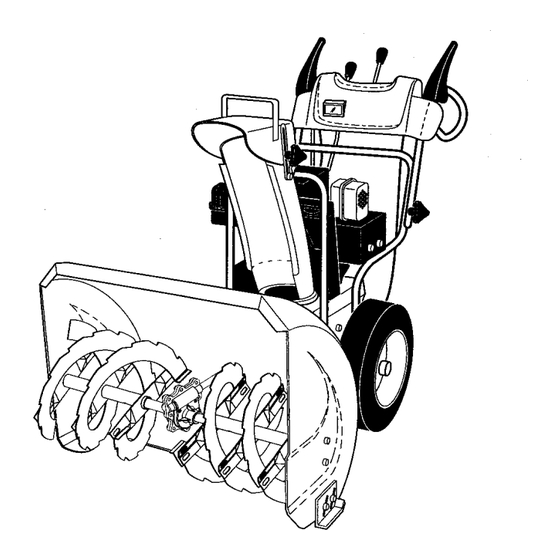
TROUBLESHOOTING See appropriate section in manual unless directed to a qualified service center. PROBLEM CAUSE CORRECTION Does not start Fuel shut-offvalve (if so Turn fuel shut-off valve to OPEN position. equipped) in OFF position. Safety ignitionkey Insert safety ignition key. is not inserted. - Page 20 REPAIR PARTS SNOW THROWER - MODEL NUMBER PR8527ESA AUGER HOUSING / IMPELLER ASSEMBLY 44 27 "46...
- Page 21 REPAIR PARTS SNOWTHROWER- MODEL NUMBER PR8527ESA AUGER HOUSING / IMPELLER ASSEMBLY PART DESCRIPTION 53847 Washer 181083 Pulley, Impeller 175323 Bearing Assembly, Flange 155377 Nut, Hex Flange 5/16-18 180355 Bolt, Flat Head, Carriage 5/16-18 x 518 72270505 Bolt, Carriage 5/16-! 8 x 5/8...
- Page 22 REPAIR PARTS SNOWTHROWER - MODEL NUMBER PR8527ESA CONTROL PANEL/DISCHARGE CHUTE" ( _ ...... :::;;;_-...,,.., X." _14 _ ,, \...
- Page 23 REPAIR PARTS SNOWTHROWER o MODEL NUMBER PR8527ESA CONTROL PANEL / DISCHARGE CHUTE PART DESCRIPTION 183334 Knob, Lever 17501010 Screw #10-24 x 5/8 179096X479 Strap, Slotted 73800600 Nut, Lock 3/8-16 19131316 Washer, Flat 3/8 178659 Control Assembly, Chute Rotater 178638X479 Support, Pivot...
- Page 24 SNOWTHROWER - MODEL NUMBER PR8527ESA REPAIR PARTS HANDLES \• \_'f\\...
- Page 25 REPAIR PARTS SNOW THROWER - MODEL NUMBER PR8527ESA HANDLES PART DESCRIPTION 178875X479 Lever, Auger Control, RH 178648X479 Lever,Traction Drive Control, LH 179439 Nut, Cage 1/4-20 178888 Bushing, Flange 169675 Retainer, Hairpin 180402 Screw, Hax Head 1/4-20 x 3/4 178652 Rod, Interlock...
- Page 26 REPAIR PARTS SNOWTHROWER - MODEL NUMBER PR8527ESA DRIVE...
- Page 27 REPAIR PARTS SNOW THROWER - MODEL NUMBER PR8527ESA DRIVE PART DESCRIPTION 146315 Screw, Hex Head 5/16-18 x 3/4 7380O5OO Nut, Lock 5/16-18 155415 Washer, Flat 17490508 Screw, Hex Head 5/16-18 x 1/2 180017 Bearing, Flange 180134 Shaft, Auxiliary 179270 Spacer, Plate...
- Page 28 REPAIR PARTS SNOWTHROWER - MODEL NUMBER PR8527ESA, CHASSIS / ENGINE / PULLEYS...
- Page 29 REPAIR PARTS SNOWTHROWER - MODEL NUMBER PR8527ESA CHASSIS / ENGINE / PULLEYS KEY PART DESCRIPTION NO. NO. 181044 Spring, Traction Idler 180522 Pulley, Idler (2-1/4) Engine, Tecumseh, Model Number HMSK85 (Order parts from Engine manufacturer) 7478052O Screw, Hex Head 5/16-18 x 1-1/4...
- Page 30 SNOW THROWER - MODEL NUMBER PR8527ESA REPAIR PARTS WHEELS / DECALS ..:.;";;;;;- .."_°"÷+'"...
- Page 31 PART DESCRIPTION 181037 Decal, Danger 187871 Decal, Poulan .Pro, 8.5HP/27" (large) 181035 Deca_, Danger, Deflector 181042 Decal, Danger Decal, Poulan Pro, 8.5HP/27" (small) 187870 181033 Decal, Instruction 155798 Decal, Traction Lever 155800 Decal, Auger Lever 181039 Decal, Speed Control 189645...
-
Page 32: Limited Warranty
LIMITED WARRANTY ..The Manufacturer warrants to the original consumer purchaser that this product as manufactured is free from de- fects in materials and workmanship. For a period of two (2) years from date of purchase by the original consumer purchaser, we will repair or replace, at our option, without charge for parts or labor incurred in replacing parts, any part which we find to be defective due to materials or workmanship.
Need help?
Do you have a question about the PR8527ESA and is the answer not in the manual?
Questions and answers