
Related Manuals for Kramer VS-401YC


Summary of Contents for Kramer VS-401YC
- Page 1 Kramer Electronics, Ltd. USER MANUAL Model: VS-401YC 4x1 s-Video / Audio Switcher - DA...
-
Page 2: Table Of Contents
Figure 12: Atmel – Flip Window (Operation Completed) Tables Table 1: Features and Functions of the VS-401YC 4x1 s-Video / Audio Switcher - DA Table 2: VS-401YC 4x1 s-Video / Audio Switcher - DA Underside Features Table 3: VS-401YC 4x1 s-Video / Audio Switcher - DA Technical Specifications... -
Page 3: Introduction
GROUP 6: Accessories and Rack Adapters; GROUP 7: Scan Converters and Scalers; and GROUP 8: Cables and Connectors 2 Download up-to-date Kramer user manuals from our Web site: http://www.kramerelectronics.com 3 The complete list of Kramer cables is on our Web site at http://www.kramerelectronics.com... - Page 4 Getting Started s-Video Player DVD Player s-Video Camera s-Video Set Top Box s-Video Display Source Recorder KRAMER: SIMPLE CREATIVE TECHNOLOGY...
-
Page 5: Overview
Overview Overview The VS-401YC is a 4x1 switcher and distribution amplifier for s-Video and stereo audio signals, that lets you switch and distribute any of the four inputs to two identical outputs. In particular, the VS-401YC: Features video input and output signals on 4p connectors and audio input... -
Page 6: Your Vs-401Yc 4X1 S-Video / Audio Switcher - Da
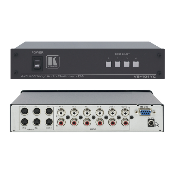
4x1 s-Video / Figure 1 and Table 1 define the VS-401YC: Figure 1: VS-401YC 4x1 s-Video / Audio Switcher - DA Table 1: Features and Functions of the VS-401YC 4x1 s-Video / Audio Switcher - DA Feature Function POWER Switch... -
Page 7: Figure 2: Vs-401Yc 4X1 S-Video / Audio Switcher - Da Underside View
Your VS-401YC 4x1 s-Video / Audio Switcher - DA Figure 2 and Table 2 define the underside of the VS-401YC: Figure 2: VS-401YC 4x1 s-Video / Audio Switcher - DA Underside view Table 2: VS-401YC 4x1 s-Video / Audio Switcher - DA Underside Features... -
Page 8: Connecting The Vs-401Yc 4X1 S-Video / Audio Switcher - Da
5. Connect the 12V DC power adapter to the power socket and connect the adapter to the mains electricity. 1 Switch OFF the power on each device before connecting it to your VS-401YC. After connecting your VS-401YC, switch on its power and then switch on the power on each device... -
Page 9: Figure 3: Connecting The Vs-401Yc 4X1 S-Video / Audio Switcher - Da
Connecting the VS-401YC 4x1 s-Video / Audio Switcher - DA Audio Connections are not Shown s-Video Player DVD Player s-Video Camera Set Top Box s-Video s-Video Source Recorder Display Figure 3: Connecting the VS-401YC 4x1 s-Video / Audio Switcher - DA... -
Page 10: Connecting A Pc
Connecting the VS-401YC 4x1 s-Video / Audio Switcher - DA 5.1 Connecting a PC You can connect a PC (or other controller) to the VS-401YC via the RS-232 port. To connect using the Null-modem adapter provided with the machine (recommended method):... -
Page 11: Flash Memory Upgrade
Before installing the latest Kramer firmware version on a VS-401YC unit, do the following: 1. Connect the RS-232 DB9 rear panel port on the VS-401YC unit to the Null-modem adapter and connect the Null-modem adapter with a 9-wire flat cable to the RS-232 DB9 COM port on your PC (see section 5.1). -
Page 12: Figure 5: Splash Screen
Figure 6: Atmel – Flip Window 3. Press the keyboard shortcut key F2 (or select the “Select” command from the Device menu, or press the integrated circuit icon in the upper right corner of the window). The “Device Selection” window appears: KRAMER: SIMPLE CREATIVE TECHNOLOGY... -
Page 13: Figure 7: Device Selection Window
Flash Memory Upgrade Figure 7: Device Selection Window 4. Click the button next to the name of the device and select from the list: AT89C51RD2: AT89C51RD2 T89C51RD2 Figure 8: Selecting the Device from the Selection Window 5. Click OK and select “Load Hex” from the File menu. -
Page 14: Figure 9: Loading The Hex
Figure 9: Loading the Hex 6. The Open File window opens. Select the correct HEX file that contains the updated version of the firmware for VS-401YC (for example, 401YCM_V1p2.hex) and click Open. 7. Press the keyboard shortcut key F3 (or select the “Communication / RS232”... -
Page 15: Figure 11: Atmel - Flip Window (Connected)
Flash Memory Upgrade Verify that in the Buffer Information column, the “HEX File: VS401YC.hex” appears. VS401YC.hex Figure 11: Atmel – Flip Window (Connected) 9. Click Run. After each stage of the operation is completed, the check-box for that stage becomes colored green When the operation is completed, all 4 check-boxes will be colored green and the status bar message: Memory Verify Pass appears 1 See also the blue progress indicator on the status bar... -
Page 16: Figure 12: Atmel - Flip Window (Operation Completed)
Figure 12: Atmel – Flip Window (Operation Completed) 10. Close the “Atmel – Flip” window. 11. Disconnect the power to the VS-401YC. 12. Disconnect the RS-232 rear panel port on the VS-401YC unit from the Null-modem adapter. 13. Switch to OFF on the machine underside. -
Page 17: Technical Specifications
Technical Specifications Technical Specifications Table 3 includes the technical specifications. Table 3: VS-401YC 4x1 s-Video / Audio Switcher - DA Technical Specifications INPUTS: 4 YC, 1Vpp/75 (Y), 0.3Vpp/75 (C) on 4p connectors 4 stereo, 1Vpp/50k on RCA connectors OUTPUTS: 2 YC 1Vpp/75 (Y), 0.3Vpp/75 (C) on 4p connectors 2 stereo, 5Vpp/150 on RCA connectors MAX. -
Page 18: Vs-401Yc Communication Protocol
VS-401YC Communication Protocol VS-401YC Communication Protocol The VS-401YC is compatible with Kramer’s Protocol 2000 (version 0.46) (below). This RS-232/RS-485 communication protocol uses four bytes of information as defined below. For RS-232, a null-modem connection between the machine and controller is used. The default data rate is 9600 baud, with no parity, 8 data bits and 1 stop bit. -
Page 19: Table 5: Instruction Codes For Protocol 2000
VS-401YC Communication Protocol Table 5: Instruction Codes for Protocol 2000 Note: All values in the table are decimal, unless otherwise stated. INSTRUCTION DEFINITION FOR SPECIFIC INSTRUCTION NOTE DESCRIPTION INPUT OUTPUT RESET VIDEO SWITCH VIDEO Set equal to video input which is to... - Page 20 VS-401YC Communication Protocol INSTRUCTION DEFINITION FOR SPECIFIC INSTRUCTION NOTE DESCRIPTION INPUT OUTPUT ERROR / BUSY For invalid / valid input (i.e. 0 - error 9, 25 OUTPUT byte = 4 or OUTPUT byte 1 - invalid instruction = 5), 2 - out of range...
- Page 21 VS-401YC Communication Protocol INSTRUCTION DEFINITION FOR SPECIFIC INSTRUCTION NOTE DESCRIPTION INPUT OUTPUT VIDEO PARAMETER 1 – Input 0 - video gain SETTINGS FOR 2 – Output 1 - contrast INSTRUCTIONS 21, 2 - brightness 23, 26 3 - colour 4 - hue...
- Page 22 VS-401YC Communication Protocol NOTE 6 – If INPUT is set to 127 for these instructions, then, if the function is defined on this machine, it replies with OUTPUT=1. If the function is not defined, then the machine replies with OUTPUT=0, or with an error (invalid instruction code).
- Page 23 VS-401YC Communication Protocol code is sent again. (The mode is automatically cancelled after implementation of the switch if the “execute” command is used). For example, to connect input 4 to output 3 after a delay, send HEX codes (set for delayed switch)
- Page 24 EXCLUSION OF DAMAGES The liability of Kramer for any effective products is limited to the repair or replacement of the product at our option. Kramer shall not be liable for: Damage to other property caused by defects in this product, damages based upon inconvenience, loss of use of the product, loss of time, commercial loss;...
- Page 25 For the latest information on our products and a list of Kramer distributors, visit our Web site: www.kramerelectronics.com, where updates to this user manual may be found. We welcome your questions, comments and feedback. Safety Warning: Disconnect the unit from the power supply before opening/servicing.
Need help?
Do you have a question about the VS-401YC and is the answer not in the manual?
Questions and answers