Table of Contents
Advertisement
Quick Links
Advertisement
Table of Contents

Subscribe to Our Youtube Channel
Related Manuals for Kramer TOOLS 900xl


Summary of Contents for Kramer TOOLS 900xl
-
Page 1: User Manual
Kramer Electronics, Ltd. USER MANUAL Model: 900xl Power Amplifier... -
Page 2: Table Of Contents
Technical Specifications Hex Table Kramer Protocol 2000 Figures Figure 1: 900xl Power Amplifier – Top, Front, and Rear Views Figure 2: 900xl Power Amplifier – Underside View Figure 3: Connecting the 900xl Power Amplifier Figure 4: RS-232 Control Cable Tables... -
Page 3: Introduction
GROUP 7: Scan Converters and Scalers; GROUP 8: Cables and Connectors; GROUP 9: Room Connectivity; GROUP 10: Accessories and Rack Adapters; GROUP 11: Sierra Products 2 Download up-to-date Kramer user manuals from our Web site at http://www.kramerelectronics.com 3 The complete list of Kramer cables is on our Web site at http://www.kramerelectronics.com... -
Page 4: Quick Start
Kramer Electronics branded equipment on arrival at the EARN facility. For details of Kramer’s recycling arrangements in your particular country go to our recycling pages at http://www.kramerelectronics.com/support/recycling/. Quick Start This quick start chart summarizes the basic setup and operation steps. -
Page 5: Overview
Overview Overview The Kramer 900xl is a high-performance power amplifier for line-level stereo audio signals. It accepts either a stereo audio signal on an RCA connector or a stereo audio signal on a 3.5mm mini jack. It delivers a speaker output of 10 watts RMS per channel into a 4Ω load on a 10A 4-pin terminal block connector. -
Page 6: Your 900Xl Power Amplifier
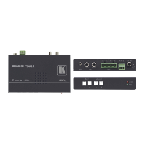
Figure Table 1, and Table 2 define the unit. Figure 1: 900xl Power Amplifier – Top, Front, and Rear Views Table 1: 900xl Power Amplifier Front, and Rear Functions Feature Function 12V DC Connector +12V DC for powering the unit... -
Page 7: Figure 2: 900Xl Power Amplifier - Underside View
Your 900xl Power Amplifier Figure 2: 900xl Power Amplifier – Underside View Table 2: 900xl Power Amplifier Underside Functions Feature Function LEVEL L/H Switch Input level – low / high gain; set to low in case of distortion PROG ON Switch... -
Page 8: Connecting The 900Xl Power Amplifier
Connecting the 900xl Power Amplifier Connecting the 900xl Power Amplifier To connect the 900xl, as illustrated in Figure 3, perform the following: 1. Connect an unbalanced stereo audio source (for example, a computer audio line out) to the IN 1 mini jack connector. -
Page 9: Connecting A Pc
Operating the 900xl Power Amplifier Connecting a PC You can control the 900xl with a PC (or other controllers) via the RS-232 port using serial commands. To connect a PC to the 900xl: • Connect the RS-232 9-pin D-sub port on your PC to the RS-232... -
Page 10: Using Serial Commands
Technical Specifications Using Serial Commands To operate your device using serial commands, you need to install Kramer's control software For an explanation of all control commands, see sections and 9. Technical Specifications 900xl technical specifications are shown in Table Table 3: 900xl Technical Specifications INPUTS: 1 unbalanced stereo audio on a 3.5mm mini-jack connector;... -
Page 11: Hex Table
Hex Table Hex Table Table 4 lists the Hex values (described in section 9) for the 900xl: Table 4: 900xl Hex Table Instruction # Hex Code Description 2. Switch Audio 02 81 81 81 Connect Input 1 to output 02 82 81 81 Connect Input 2 to output 22. -
Page 12: Table 6: Instruction Codes For Protocol 2000
7 - remote control name 8 - remote software version 9 - Protocol 2000 revision DEFINE MACHINE 1 - number of inputs 2 - for audio 2 - number of outputs 3 - number of setups KRAMER: SIMPLE CREATIVE TECHNOLOGY... - Page 13 Kramer Protocol 2000 NOTES on the above table: NOTE 1 – When the master switcher is reset, (e.g. when it is turned on), the reset code is sent to the PC. If this code is sent to the switchers, it will reset according to the present power-down settings.
- Page 15 For the latest information on our products and a list of Kramer distributors, visit our Web site: www.kramerelectronics.com where updates to this user manual may be found. We welcome your questions, comments and feedback. Safety Warning: Disconnect the unit from the power supply before opening/servicing.
Need help?
Do you have a question about the TOOLS 900xl and is the answer not in the manual?
Questions and answers