IBM System x3650 M3 4255 Installation And User Manual
Types 4255, 7945, 7949 installation and user’s guide
Hide thumbs
Also See for System x3650 M3 4255:
- Service manual (316 pages) ,
- Installation and user manual (210 pages) ,
- Product manual (48 pages)
Table of Contents
Advertisement
Advertisement
Table of Contents

Related Manuals for IBM System x3650 M3 4255


Summary of Contents for IBM System x3650 M3 4255
- Page 1 System x3650 M3 Types 4255, 7945, and 7949 Installation and User’s Guide...
- Page 3 System x3650 M3 Types 4255, 7945, and 7949 Installation and User’s Guide...
- Page 4 Note: Before using this information and the product it supports, read the general information in Appendix B, “Notices,” on page 163, the IBM Safety Information and IBM Environmental Notices and User's Guide on the IBM System x Documentation CD, and the IBM Warranty Information document that comes with your server.
-
Page 5: Table Of Contents
... . 11 IBM Systems Director ..... . 12 The UpdateXpress System Pack Installer ....13 Server controls, LEDs, and power . - Page 6 IBM Advanced Settings Utility program....159 Updating IBM Systems Director ....159...
- Page 7 Hardware service and support ....162 IBM Taiwan product service ....162 Appendix B.
- Page 8 System x3650 M3 Types 4255, 7945, and 7949: Installation and User’s Guide...
-
Page 9: Safety
Les sikkerhetsinformasjonen (Safety Information) før du installerer dette produktet. Antes de instalar este produto, leia as Informações sobre Segurança. Antes de instalar este producto, lea la información de seguridad. Läs säkerhetsinformationen innan du installerar den här produkten. © Copyright IBM Corp. 2012... - Page 10 Read any additional safety information that comes with the server or optional device before you install the device. Attention: Use No. 26 AWG or larger UL-listed or CSA certified telecommunication line cord. viii System x3650 M3 Types 4255, 7945, and 7949: Installation and User’s Guide...
- Page 11 Statement 1: DANGER Electrical current from power, telephone, and communication cables is hazardous. To avoid a shock hazard: v Do not connect or disconnect any cables or perform installation, maintenance, or reconfiguration of this product during an electrical storm. v Connect all power cords to a properly wired and grounded electrical outlet.
- Page 12 Statement 2: CAUTION: When replacing the lithium battery, use only IBM Part Number 33F8354 or an equivalent type battery recommended by the manufacturer. If your system has a module containing a lithium battery, replace it only with the same module type made by the same manufacturer.
- Page 13 Statement 3: CAUTION: When laser products (such as CD-ROMs, DVD drives, fiber optic devices, or transmitters) are installed, note the following: v Do not remove the covers. Removing the covers of the laser product could result in exposure to hazardous laser radiation. There are no serviceable parts inside the device.
- Page 14 The device also might have more than one power cord. To remove all electrical current from the device, ensure that all power cords are disconnected from the power source. System x3650 M3 Types 4255, 7945, and 7949: Installation and User’s Guide...
- Page 15 Statement 8: CAUTION: Never remove the cover on a power supply or any part that has the following label attached. Hazardous voltage, current, and energy levels are present inside any component that has this label attached. There are no serviceable parts inside these components.
- Page 16 System x3650 M3 Types 4255, 7945, and 7949: Installation and User’s Guide...
-
Page 17: Chapter 1. The System X3650 M3 Server
Problem Determination and Service Guide that is on the IBM Documentation CD. The IBM System x3650 M3 Types 4255, 7945, or 7949 server is a 2-U -high server that is ideally suited for networking environments that require superior microprocessor performance, efficient memory management, and flexibility. - Page 18 The SAS ID for each bay is printed on the server front, above each bay. If firmware and documentation updates are available, you can download them from the IBM Web site. The server might have features that are not described in the documentation that comes with the server, and the documentation might be updated...
-
Page 19: The Ibm Documentation Cd
Note: The illustrations in this document might differ slightly from your hardware. ID label You can download an IBM ServerGuide Setup and Installation CD to help you configure the hardware, install device drivers, and install the operating system. For more information, see “Using the ServerGuide Setup and Installation CD” on page 150. -
Page 20: Related Documentation
This printed document contains information about the terms of the warranty. v Safety Information This document is in PDF on the IBM Documentation CD. It contains translated caution and danger statements. Each caution and danger statement that appears in the documentation has a number that you can use to locate the corresponding statement in your language in the Safety Information document. - Page 21 1. Go to http://www.ibm.com/systems/support/. 2. Under Product support, click System x. 3. Under Popular links, click Publications lookup. 4. From the Product family menu, select System x3650 M3 and click Continue. Chapter 1. The System x3650 M3 server...
-
Page 22: Notices And Statements In This Document
The declared sound-power levels indicate an upper limit, below which a large number of computers will operate. System x3650 M3 Types 4255, 7945, and 7949: Installation and User’s Guide... - Page 23 – Two 133 MHz/64-bit PCI-X 1.0a slots Note: In messages and documentation, – One PCI Express x16 slot (x16 the term service processor refers to the lanes) integrated management module (IMM). Chapter 1. The System x3650 M3 server...
-
Page 24: What Your Server Offers
Optionally, the IMM also provides a virtual presence capability for remote server management capabilities. The IMM provides remote server management through industry-standard interfaces: – Intelligent Platform Management Interface (IPMI) version 2.0 System x3650 M3 Types 4255, 7945, and 7949: Installation and User’s Guide... - Page 25 – Event logs for ServeRAID controllers and service processors The diagnostic programs create a merged log that includes events from all collected logs. The information is collected into a file that you can send to IBM service and support. Additionally, you can view the information locally through a generated text report file.
- Page 26 The addition of the optional Ethernet daughter card provides failover capability to a redundant Ethernet connection with the applicable application installed. If a problem occurs with the primary Ethernet connection and the optional Ethernet System x3650 M3 Types 4255, 7945, and 7949: Installation and User’s Guide...
-
Page 27: Reliability, Availability, And Serviceability Features
The server contains an integrated management module (IMM) which enables you to manage the functions of the server locally and remotely. The addition of the optional IBM Virtual Media Key provides remote presence and blue-screen capture capability. The IMM also provides system monitoring, event recording, and dial-out alert capability. -
Page 28: Ibm Systems Director
A set of common tasks that are included with IBM Systems Director provides many of the core capabilities that are required for basic management, which means instant out-of-the-box business value. -
Page 29: The Updatexpress System Pack Installer
Managing the life cycles of virtual resources For more information about IBM Systems Director, see the documentation on the IBM Systems Director DVD that comes with the server and the IBM xSeries Systems Management Web page at http://www.ibm.com/systems/management/, which presents an overview of IBM Systems Management and IBM Systems Director. -
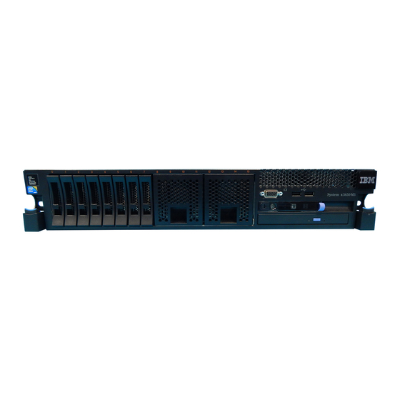
Page 30: Front View
Optional CD/DVD-eject button: Press this button to release a CD or DVD from the CD-RW/DVD drive. Optional CD/DVD drive activity LED: When this LED is lit, it indicates that the CD-RW/DVD drive is in use. System x3650 M3 Types 4255, 7945, and 7949: Installation and User’s Guide... -
Page 31: Operator Information Panel
Locator button and locator LED: Use this LED to visually locate the server among other servers. Press this button to turn on or turn off this LED locally. You can use IBM Systems Director to light this LED remotely. Light path diagnostics panel The light path diagnostics panel is on the top of the operator information panel. - Page 32 The reset button is in the lower-right corner of the light path diagnostics panel. For more information about light path diagnostics, see the Problem Determination and Service Guide on the IBM Documentation CD. System x3650 M3 Types 4255, 7945, and 7949: Installation and User’s Guide...
-
Page 33: Rear View
Ethernet LAN that is connected to the Ethernet port. Ethernet link LEDs: When these LEDs are lit, they indicate that there is an active link connection on the 10BASE-T, 100BASE-TX, or 1000BASE-TX interface for the Ethernet port. Chapter 1. The System x3650 M3 server... - Page 34 This LED is the same as the system-error LED on the front of the server. Locator LED: Use this LED to visually locate the server among other servers. You can use IBM Systems Director to light this LED remotely. This LED is the same as the system-locator LED on the front of the server.
- Page 35 The following table describes the problems that are indicated by various combinations of the power-supply LEDs and the power-on LED on the operator information panel and suggested actions to correct the detected problems. Chapter 1. The System x3650 M3 server...
- Page 36 The following table describes the problems that are indicated by various combinations of the power-supply LEDs on a dc power supply and suggested actions to correct the detected problems. System x3650 M3 Types 4255, 7945, and 7949: Installation and User’s Guide...
-
Page 37: Server Power Features
(IMM) is shut down; however, the server can respond to requests from the IMM, such as a remote request to turn on the server. The power-on LED flashes to indicate that the server is connected to power but is not turned on. Chapter 1. The System x3650 M3 server... -
Page 38: Turning On The Server
You can press the power-control button to start an orderly shutdown of the operating system and turn off the server, if your operating system supports this feature. System x3650 M3 Types 4255, 7945, and 7949: Installation and User’s Guide... - Page 39 4 seconds to turn off the server. v The IMM can turn off the server as an automatic response to a critical system failure. v You can turn off the server through a request from the IMM. Chapter 1. The System x3650 M3 server...
- Page 40 System x3650 M3 Types 4255, 7945, and 7949: Installation and User’s Guide...
-
Page 41: Chapter 2. Installing Optional Devices
3. Shut down and restart the server multiple times to ensure that the server is correctly configured and functions correctly with the newly installed devices. 4. Save the DSA log as a file and send it to IBM. © Copyright IBM Corp. 2012... -
Page 42: Server Components
IBM procedures for shipping. Support information for IBM Business Partners is available at http://www.ibm.com/ partnerworld/. Server components The following illustrations show the major components in the server. System x3650 M3 Types 4255, 7945, and 7949: Installation and User’s Guide... - Page 43 Note: The illustrations in this document might differ slightly from your hardware. Chapter 2. Installing optional devices...
-
Page 44: System-Board Internal Connectors
System-board internal connectors The following illustration shows the internal connectors on the system board. System x3650 M3 Types 4255, 7945, and 7949: Installation and User’s Guide... -
Page 45: System-Board External Connectors
System-board external connectors The following illustration shows the external input/output connectors on the system board. Chapter 2. Installing optional devices... -
Page 46: System-Board Switches And Jumpers
Pins 1 and 2: Normal (default) Loads the primary server recovery firmware ROM page. jumper v Pins 2 and 3: Loads the secondary (backup) server firmware ROM page. System x3650 M3 Types 4255, 7945, and 7949: Installation and User’s Guide... - Page 47 Table 3. System board jumpers (continued) Jumper Jumper number name Jumper setting J147 v Pins 1 and 2: Normal (default) Loads the primary IMM recovery firmware ROM page. jumper v Pins 2 and 3: Loads the secondary (backup) IMM firmware ROM page.
- Page 48 39, and “Turning off the server” on page 22.) 2. Any system-board switch or jumper blocks that are not shown in the illustrations in this document are reserved. System x3650 M3 Types 4255, 7945, and 7949: Installation and User’s Guide...
-
Page 49: System-Board Leds
System-board LEDs The following illustration shows the light-emitting diodes (LEDs) on the system board. Note: Error LEDs remain lit only while the server is connected to power. System pulse LEDs The following LEDs are on the system board and monitor the system power-on and power-off sequencing and boot progress (see “System-board LEDs”... -
Page 50: System-Board Optional Device Connectors
System-board optional device connectors The following illustration shows the connectors on the system board for user-installable options. System x3650 M3 Types 4255, 7945, and 7949: Installation and User’s Guide... -
Page 51: Sas Riser-Card Connectors And Leds
SAS riser-card connectors and LEDs The following illustrations show the connectors and LEDs on the SAS riser-cards. Note: Error LEDs remain lit only while the server is connected to power. A 16-drive-capable model server contains the riser card that is shown in the following illustration. -
Page 52: Pci Riser-Card Adapter Connectors
Note: Error LEDs remain lit only while the server is connected to power. Upper PCI slot error LED (Adaptor card error LED) Lower PCI slot error LED System x3650 M3 Types 4255, 7945, and 7949: Installation and User’s Guide... -
Page 53: Installation Guidelines
2. Under Product support, click System x. 3. Under Popular links, click Software and device drivers. 4. Click System x3650 M3 to display the matrix of downloadable files for the server. For additional information about tools for updating, managing, and deploying firmware, see the System x and xSeries Tools Center at http://publib.boulder.ibm.com/infocenter/toolsctr/v1r0/index.jsp. -
Page 54: System Reliability Guidelines
When you are finished working on the server, reinstall all safety shields, guards, labels, and ground wires. v For a list of supported optional devices for the server, see http://www.ibm.com/ servers/eserver/serverproven/compat/us/. System reliability guidelines... -
Page 55: Handling Static-Sensitive Devices
The server supports hot-plug, hot-add, and hot-swap devices and is designed to operate safely while it is turned on and the cover is removed. Follow these guidelines when you work inside a server that is turned on: v Avoid wearing loose-fitting clothing on your forearms. Button long-sleeved shirts before working inside the server;... -
Page 56: Internal Cable Routing And Connectors
Do not disconnect the cable by using excessive force. Failing to disconnect the cable properly may damage the connector on the system board. Any damage to the connector may require replacing the system board. System x3650 M3 Types 4255, 7945, and 7949: Installation and User’s Guide... - Page 57 Chapter 2. Installing optional devices...
- Page 58 Note: The USB cable is routed under the video cable and then both the USB and video cables are routed under the cable retention tab and the top cover latch receptacle. System x3650 M3 Types 4255, 7945, and 7949: Installation and User’s Guide...
- Page 59 The following illustration shows the internal routing for the configuration cable. The following illustrations show the internal routing for the SAS hard disk drive backplane cables (for a 16 hard disk drive model). Chapter 2. Installing optional devices...
- Page 60 System x3650 M3 Types 4255, 7945, and 7949: Installation and User’s Guide...
-
Page 61: Removing The Cover
Removing the cover The following illustration shows how to remove the cover. Cover-release latch Important: Before you install optional hardware, make sure that the server is working correctly. Start the server, and make sure that the operating system starts, if an operating system is installed, or that a 19990305 error code is displayed, indicating that an operating system was not found but the server is otherwise working correctly. -
Page 62: Removing A Pci Riser-Card Assembly
4. Grasp the assembly at the front tab and rear edge and lift it to remove it from the server. Place the riser-card assembly on a flat, static-protective surface. System x3650 M3 Types 4255, 7945, and 7949: Installation and User’s Guide... -
Page 63: Installing A Pci Riser-Card Assembly
Installing a PCI riser-card assembly To install a PCI riser-card assembly, complete the following steps. Note: The illustrations in this document might differ slightly from your hardware. PCI riser-card PCI riser-card assembly 2 assembly 2 PCI riser-card PCI riser-card assembly 1 assembly 1 PCI riser connector 2... -
Page 64: Removing The Microprocessor 2 Air Baffle
Attention: For proper cooling and airflow, replace all air baffles before you turn on the server. Operating the server with any air baffle removed might damage server components. System x3650 M3 Types 4255, 7945, and 7949: Installation and User’s Guide... -
Page 65: Installing The Microprocessor 2 Air Baffle
Installing the microprocessor 2 air baffle To install the microprocessor 2 air baffle, complete the following steps: 1. Read the safety information that begins on page vii and “Installation guidelines” on page 37. 2. Make sure that the server and peripheral devices are turned off (see “Turning off the server”... -
Page 66: Removing The Dimm Air Baffle
Attention: For proper cooling and airflow, replace all air baffles before you turn on the server. Operating the server with any air baffle removed might damage server components. System x3650 M3 Types 4255, 7945, and 7949: Installation and User’s Guide... -
Page 67: Installing The Dimm Air Baffle
Installing the DIMM air baffle The following illustration shows how to install the DIMM air baffle. PCI riser-card assembly 1 DIMM air baffle To install the DIMM air baffle, complete the following steps: 1. Read the safety information that begins on page vii and “Installation guidelines” on page 37. -
Page 68: Installing The Full-Length-Adapter Bracket
2. Align the bracket with the storage location on the riser-card assembly as shown. 3. Place the two hooks 1 in the two openings 2 in the storage location on the riser-card assembly. System x3650 M3 Types 4255, 7945, and 7949: Installation and User’s Guide... -
Page 69: Installing A Pci Adapter
Some high performance video adapters are supported by your server. See http://www.ibm.com/servers/eserver/serverproven/compat/us/ for more information. v The following notes describe important information about the NVIDIA video adapter that comes preinstalled in some server models: –... - Page 70 4, remove PCI riser-card assembly 2. See “Removing a PCI riser-card assembly” on page 46. 6. Slide the expansion-slot cover out of the PCI riser-card assembly expansion slot. System x3650 M3 Types 4255, 7945, and 7949: Installation and User’s Guide...
- Page 71 Expansion-slot cover Adapter riser-card assembly 7. Install the adapter: a. If the adapter is a full-length adapter for the upper expansion slot in the riser card, remove the full-length-adapter bracket from underneath the top of the riser-card assembly and insert it in the end of the upper expansion slot of the riser-card assembly.
- Page 72 11. Perform any configuration tasks that are required for the adapter. If you have other devices to install or remove, do so now. Otherwise, go to “Completing the installation” on page 139. System x3650 M3 Types 4255, 7945, and 7949: Installation and User’s Guide...
-
Page 73: Removing A Pci Adapter
Removing a PCI adapter To remove an adapter from a PCI riser-card assembly, complete the following steps. Adapter Expansion-slot cover riser-card assembly 1. Read the safety information that begins on page vii and “Installation guidelines” on page 37. 2. Turn off the server and peripheral devices and disconnect all power cords and external cables (see “Turning off the server”... -
Page 74: Installing An Ibm Virtual Media Key
Press the virtual media key down into the connector until it is firmly seated on the system board. If you have other devices to install or remove, do so now. Otherwise, go to “Completing the installation” on page 139. System x3650 M3 Types 4255, 7945, and 7949: Installation and User’s Guide... -
Page 75: Installing A Hard Disk Drive
The following notes describe the type of hard disk drives that the server supports and other information that you must consider when you install a drive. For a list of supported drives, see http://www.ibm.com/servers/eserver/serverproven/compat/us/. Important: Do not install a SCSI hard disk drive in this server. -
Page 76: Removing A Hard Disk Drive
Note: You might have to reconfigure the disk arrays after you remove a hard disk drive. See the RAID documentation on the IBM ServeRAID Support CD for information about RAID controllers. If you have other devices to install or remove, do so now. Otherwise, go to “Completing the installation”... - Page 77 4. Gently push the drive assembly into the bay until the drive stops. Note: You might have to reconfigure the disk arrays after you install hard disk drives. See the RAID documentation on the IBM ServeRAID Support CD for information about RAID controllers.
-
Page 78: Removing A Simple-Swap Hard Disk Drive
Installing a SAS/SATA 4 Pac HDD upgrade option If the server is a 16-drive-capable model with four hard disk drive bays installed, you can install an IBM System x3650 M3 Hot-swap SAS/SATA 4 Pac HDD upgrade option. See http://www.ibm.com/servers/eserver/serverproven/compat/us/ for a list of supported optional devices. - Page 79 To install a 4-disk-drive optional hard disk drive backplane in a 8-drive-capable server model, complete the following steps: 1. Read the safety information that begins on page vii and “Installation guidelines” on page 37. 2. Turn off the server and disconnect all power cords and external cables (see “Turning off the server”...
- Page 80 10. Connect one end of the internal power cable that comes with the 4 Pac HDD upgrade option kit into the hot-swap SAS/SATA power connector on the system board. 11. Remove hard disk drive backplane from the server. System x3650 M3 Types 4255, 7945, and 7949: Installation and User’s Guide...
- Page 81 a. From backplane, disconnect the following cables in the order listed: v Power cable 1 v SAS signal cable 2 v Configuration cable 3 b. Lift the backplane out of the server by pulling it toward the rear of the server and then lifting it up.
- Page 82 14. Remove the rear controller retention bracket located in the battery bay above the power supplies by pulling up the release tab 1 and sliding the bracket outward 2 . System x3650 M3 Types 4255, 7945, and 7949: Installation and User’s Guide...
- Page 83 15. Install the SAS controller front retention bracket that you got from step 14: a. Align the retention bracket controller slot so that it faces the rear of the server. b. Place the bracket tabs in the holes on the chassis and slide the bracket to left until it clicks into place.
-
Page 84: Installing A Sas/Sata 8 Pac Hdd Option
Installing a SAS/SATA 8 Pac HDD option If the server is a 16-drive-capable model with eight hard disk drive bays installed, you can install an IBM System x3650 M3 Hot-swap SAS/SATA 8 Pac HDD option. See http://www.ibm.com/servers/eserver/serverproven/compat/us/ for a list of supported optional devices. - Page 85 4. Remove the two 4-drive filler panels that are to the right of drive bay 8, beneath the IDs 8 - 15 on the front bezel. 5. To obtain more working room, remove fans 2 and 3 (see “Removing a hot-swap fan”...
- Page 86 10. Connect one end of the internal power cable that comes with the 8 Pac HDD option kit into the empty hot-swap SAS/SATA power connector on the system board. 11. Remove hard disk drive backplane 1 from the server. System x3650 M3 Types 4255, 7945, and 7949: Installation and User’s Guide...
- Page 87 a. From backplane 1, disconnect the following cables in the order listed: v Power cable 1 v SAS signal cable 2 v Configuration cable 3 b. Lift backplane 1 out of the server by pulling it toward the rear of the server and then lifting it up.
- Page 88 13. Install hard disk drive backplane 1: a. Connect the right-angle end of the longer SAS signal cable that comes with the option kit to hard disk drive backplane 1 1 . System x3650 M3 Types 4255, 7945, and 7949: Installation and User’s Guide...
- Page 89 b. Reconnect the power cable 2 to backplane 1. c. Reconnect the configuration cable 3 to backplane 1. d. Angle the backplane and place the bottom edge into the slots for backplane 1 on the chassis. e. Rotate the backplane upright so that the bracket goes underneath the latch and tabs on the chassis and is engaged into the slots on the backplane bracket.
- Page 90 Press the riser card into place until the latch at the rear of the card snaps closed. System x3650 M3 Types 4255, 7945, and 7949: Installation and User’s Guide...
- Page 91 19. If a battery and battery carrier are attached to the SAS controller that you removed in step 8, disconnect the battery carrier cable from the battery and remove the three screws that secure the battery carrier to the SAS controller. Set the battery and battery carrier aside.
- Page 92 Align the metal bracket so that the tabs are on the back side of the SAS controller and the holes on the tabs align with the holes on the SAS controller. System x3650 M3 Types 4255, 7945, and 7949: Installation and User’s Guide...
- Page 93 c. From the front side of the SAS controller, install the two screws that hold the metal bracket onto the SAS controller. 22. If required, connect one end of the remote battery cable to the interposer card. Attention: To avoid damage to the hardware, make sure that you align the black dot on the cable connector with the black dot on the connector on the interposer card.
- Page 94 Connect the SAS signal cables from hard disk drive backplane 1 to the left front connectors on the SAS expander card (as facing the front of the server). System x3650 M3 Types 4255, 7945, and 7949: Installation and User’s Guide...
-
Page 95: Installing A Sas/Sata 8 Pac Hdd For 2 Raid Kit With 2 M5015 Adapters Option
If the server is a 16-drive-capable model with eight hard disk drive bays installed, you can install an IBM System x3650 M3 Hot-swap SAS/SATA 8 Pac HDD option. See http://www.ibm.com/servers/eserver/serverproven/compat/us/ for a list of supported optional devices. To order a SAS/SATA 8 Pac HDD for 2 RAID kit with 2 M5015 adapters option, contact your IBM marketing representative or authorized reseller. - Page 96 7. Disconnect the SAS signal cables from the SAS controller, which is connected to the SAS riser-card. Leave the other end of the SAS signal cables connected to the hard disk drive backplanes. System x3650 M3 Types 4255, 7945, and 7949: Installation and User’s Guide...
- Page 97 8. Remove the SAS controller assembly from the server; then, remove the SAS controller from the SAS riser-card. See “Removing a ServeRAID SAS controller from the SAS riser-card” on page 121 for instructions. 9. Remove the SAS controller front retention bracket from the server. Chapter 2.
- Page 98 11. Remove hard disk drive backplane 1 from the server. a. From backplane 1, disconnect the following cables in the order listed: v Power cable 1 v SAS signal cable 2 v Configuration cable 3 System x3650 M3 Types 4255, 7945, and 7949: Installation and User’s Guide...
- Page 99 b. Lift backplane 1 out of the server by pulling it toward the rear of the server and then lifting it up. 12. Install the new backplane in slot 2: a. Move the SAS signal cable from hard disk drive backplane 1 to new backplane 2 1 .
- Page 100 15. Remove the rear controller retention bracket located in the battery bay above the power supplies by pulling up the release tab 1 and sliding the bracket outward 2 . System x3650 M3 Types 4255, 7945, and 7949: Installation and User’s Guide...
- Page 101 16. Install the SAS controller front retention bracket that you got from step 15. a. Align the retention bracket controller slot so that it faces the rear of the server. b. Place the bracket tabs in the holes on the chassis and slide the bracket to left until it clicks into place.
- Page 102 19. Remove the expansion-slot bracket that is screwed to the vertical wall above the power supply and install the expansion-slot bracket on another M5015 adapter: a. Orient the M5015 adapter as shown in the illustration. System x3650 M3 Types 4255, 7945, and 7949: Installation and User’s Guide...
- Page 103 21. Remove the PCI riser-card assembly 2 (see the "Removing a PCI riser-card assembly" section of the IBM System x3650 M3 Installation and User's Guide). 22. Orient the M5015 adapter so that the connectors are on the underside of the controller.
- Page 104 Connect the shorter SAS signal cable to the left front connector of hard disk drive backplane 2. b. Connect the longer SAS signal cable to the right front connector of hard disk drive backplane 2. System x3650 M3 Types 4255, 7945, and 7949: Installation and User’s Guide...
-
Page 105: Installing An Optional Tape Drive
The IBM System x3650 M3 RDX-DDS internal enablement kit is used to install an IBM tape drive in an IBM System x3650 M3 server. The IBM System x3650 M3 RDX-DDS internal enablement kit is compatible only with the following tape drives:... -
Page 106: Converting A 16 Bay System To A 8 Bay + Tape System
7. Shift the SAS hard disk drive backplane to the right to create enough space to install a tape drive. System x3650 M3 Types 4255, 7945, and 7949: Installation and User’s Guide... - Page 107 a. To obtain more working room, remove fans 2 and 3 (see “Removing a hot-swap fan” on page 115) and fan bracket. b. Lift the backplane out of the server by pulling it toward the rear of the server and then lifting it up. c.
-
Page 108: Installing The Tape Drive Option
Installing the tape drive option The following illustration shows how to install an optional tape drive. To install a SATA or USB tape drive, complete the following steps: System x3650 M3 Types 4255, 7945, and 7949: Installation and User’s Guide... - Page 109 1. Read the safety information that begins on page vii, “Installation guidelines” on page 37, and “Handling static-sensitive devices” on page 39. 2. Turn off the server and peripheral devices, and disconnect the power cords and all external cables. 3. Install the tape drive on the tray as shown in the following illustration. If the tape drive comes with a metal spacer attached, remove the spacer before you install the tape drive on the tray.
- Page 110 Configuration cable to the configuration connector on each hard disk drive backplane 9. Connect the tape-enabled configuration cable to the system board. 10. Install the hard disk drive backplanes. System x3650 M3 Types 4255, 7945, and 7949: Installation and User’s Guide...
- Page 111 a. Align the backplane with the backplane slot in the chassis and the small slots on top of the hard disk drive cage. b. Lower the backplane into the slots on the chassis. c. Rotate the top of the backplane until the front tab clicks into place into the latches on the chassis.
- Page 112 16. Push the latch to the closed (locked) position. If you have other devices to install or remove, do so now. Otherwise, go to “Completing the installation” on page 139. System x3650 M3 Types 4255, 7945, and 7949: Installation and User’s Guide...
-
Page 113: Installing A Second Microprocessor
2. Under Product support, click System x. 3. Under Popular links, click Software and device drivers. 4. Click System x3650 M3 to display the matrix of downloadable files for the server. v (Optional) Obtain an SMP-capable operating system. For a list of supported operating systems and optional devices, see http://www.ibm.com/servers/eserver/... - Page 114 5. Remove the microprocessor air baffle (see “Removing the microprocessor 2 air baffle” on page 48). 6. Locate the second microprocessor socket on the system board. 7. Rotate the heat-sink release lever to the fully open position. System x3650 M3 Types 4255, 7945, and 7949: Installation and User’s Guide...
- Page 115 8. Install the microprocessor: a. Rotate the microprocessor release lever on the socket from its closed and locked position until it stops in the fully open position. b. Rotate the hinged microprocessor bracket frame into the open position. c. Remove the microprocessor socket dust cover from the surface of the microprocessor socket, if one is present.
- Page 116 Installation tool Microprocessor Microprocessor cover release tabs Microprocessor cover i. Carefully align the microprocessor installation tool over the microprocessor socket. System x3650 M3 Types 4255, 7945, and 7949: Installation and User’s Guide...
- Page 117 Touching the thermal grease will contaminate it. If the thermal grease is contaminated, call IBM service and support to request a replacement thermal grease kit. For information about installing the replacement thermal grease, see “Thermal grease”...
- Page 118 11. Install PCI riser-card assembly 2 (see “Installing a PCI riser-card assembly” on page 47). If you have other devices to install or remove, do so now. Otherwise, go to “Completing the installation” on page 139. System x3650 M3 Types 4255, 7945, and 7949: Installation and User’s Guide...
-
Page 119: Thermal Grease
Thermal grease The thermal grease must be replaced whenever the heat sink has been removed from the top of the microprocessor and is going to be reused or when debris is found in the grease. To replace damaged or contaminated thermal grease on the microprocessor and heat exchanger, complete the following steps: 1. -
Page 120: Installing A Memory Module
1 = single-rank 2 = dual-rank 4 = quad-rank ff is the device organization (bit width) 4 = x4 organization (4 DQ lines per SDRAM) System x3650 M3 Types 4255, 7945, and 7949: Installation and User’s Guide... - Page 121 8 = x8 organization 16 = x16 organization wwwww is the DIMM bandwidth, in MBps 6400 = 6.40 GBps (PC3-800 SDRAMs, 8-byte primary data bus) 8500 = 8.53 GBps (PC3-1066 SDRAMs, 8-byte primary data bus) 10600 = 10.66 GBps (PC3-1333 SDRAMs, 8-byte primary data bus) 12800 = 12.80 GBps PC3-1600 SDRAMs, 8-byte primary data bus) m is the DIMM type E = Unbuffered DIMM (UDIMM) with ECC (x72-bit module data bus)
-
Page 122: Dimm Installation Sequence
Important: If you have configured the server to use memory mirroring, do not use the order in Table 8 on page 107; go to “Memory mirroring” on page 107 and use the installation order shown there. System x3650 M3 Types 4255, 7945, and 7949: Installation and User’s Guide... -
Page 123: Memory Mirroring
Table 8. DIMM installation sequence for non-mirroring (normal) mode Installed microprocessors DIMM connector population sequence Microprocessor socket 1 Install the DIMMs in the following sequence: 3, 6, 9, 2, 5, 8, 1, 4, 7 Microprocessor socket 2 Install the DIMMs in the following sequence: 12, 15, 18, 11, 14, 17, 10, 13, 16 Memory mirroring Memory-mirroring mode replicates and stores data on two pairs of DIMMs within... - Page 124 2; you do not have to wait until all of the DIMM connectors for microprocessor 1 are filled. CPU2 17 18 CPU1 Figure 2. Memory connectors associated with each microprocessor System x3650 M3 Types 4255, 7945, and 7949: Installation and User’s Guide...
-
Page 125: Online-Spare Memory
The following table lists the installation sequence for installing DIMMs in memory-mirroring mode. Table 10. Memory-mirroring mode DIMM population sequence Number of installed DIMMs microprocessors DIMM connector First pair of DIMMs 3, 6 Second pair of DIMMs 2, 5 Third pair of DIMMs 1, 4 Fourth pair of DIMMs 12, 15... -
Page 126: Installing A Dimm
4. If PCI riser-card assembly 1 contains one or more adapters, remove riser-card assembly 1 (see “Removing a PCI riser-card assembly” on page 46). 5. Remove the DIMM air baffle (see “Removing the DIMM air baffle” on page 50). System x3650 M3 Types 4255, 7945, and 7949: Installation and User’s Guide... - Page 127 Attention: To avoid breaking the retaining clips or damaging the DIMM connectors, open and close the clips gently. 6. Open the retaining clip on each end of the DIMM connector. 7. Touch the static-protective package that contains the DIMM to any unpainted metal surface on the server.
-
Page 128: Installing A Hot-Swap Ac Power Supply
Before you install an additional power supply or replace a power supply with one of a different wattage, you may use the IBM Power Configurator utility to determine current system power consumption. For more information and to download the utility, go to http://www-03.ibm.com/systems/bladecenter/resources/ powerconfig.html. - Page 129 CAUTION: The power control button on the device and the power switch on the power supply do not turn off the electrical current supplied to the device. The device also might have more than one power cord. To remove all electrical current from the device, ensure that all power cords are disconnected from the power source.
- Page 130 HZ 9. (IBM Business Partners only) Restart the server. Confirm that it starts correctly and recognizes the newly installed devices, and make sure that no error LEDs are lit. System x3650 M3 Types 4255, 7945, and 7949: Installation and User’s Guide...
-
Page 131: Removing A Hot-Swap Fan
10. (IBM Business Partners only) Complete the additional steps in “Instructions for IBM Business Partners” on page 25. If you have other devices to install or remove, do so now. Otherwise, go to “Completing the installation” on page 139. Removing a hot-swap fan The server comes with three replaceable fans. -
Page 132: Installing A Hot-Swap Fan
If you have other devices to install or remove, do so now. Otherwise, go to “Completing the installation” on page 139. System x3650 M3 Types 4255, 7945, and 7949: Installation and User’s Guide... -
Page 133: Removing The Sas Riser-Card And Controller Assembly
Removing the SAS riser-card and controller assembly To remove the SAS riser-card and controller assembly from the server, complete the steps for the applicable server model. v 16-drive-capable server model: 1. Press the assembly release latch toward the rear of the server and lift that end of the SAS controller assembly a little. -
Page 134: Installing The Sas Riser-Card And Controller Assembly
1. If you are replacing a ServeRAID-BR10il v2 SAS/SATA controller with a ServeRAID-M5015/M5014 SAS/SATA controller, you have to swap the controller retention brackets to fit the new SAS controller. System x3650 M3 Types 4255, 7945, and 7949: Installation and User’s Guide... - Page 135 a. Remove the SAS controller front retention bracket from the server. b. Remove the rear controller retention bracket located in the battery bay above the power supplies by pulling up the release tab 1 and sliding the bracket outward 2 . Chapter 2.
- Page 136 3. Press down on the SAS riser-card and the rear edge of the SAS controller until the SAS riser-card is firmly seated and the SAS controller card retention latch clicks into place. System x3650 M3 Types 4255, 7945, and 7949: Installation and User’s Guide...
-
Page 137: Removing A Serveraid Sas Controller From The Sas Riser-Card
You can replace the ServeRAID SAS controller with another supported ServeRAID SAS controller. For a list of supported ServeRAID SAS controllers, see http://www.ibm.com/servers/eserver/serverproven/compat/us/. Note: For brevity, in this documentation the ServeRAID SAS controller is often referred to as the SAS controller. - Page 138 ServeRAID adapter and keep it in future use. 8. If you are replacing the SAS controller with another supported SAS controller, continue with “Installing a ServeRAID SAS controller on the SAS riser-card” on page 123. System x3650 M3 Types 4255, 7945, and 7949: Installation and User’s Guide...
-
Page 139: Installing A Serveraid Sas Controller On The Sas Riser-Card
Installing a ServeRAID SAS controller on the SAS riser-card Important: If you have installed a SAS expander card in a 16-drive-capable server, the SAS controller is installed in a PCI riser-card assembly and is installed and removed the same way as any other PCI adapter. Do not use the instructions in this topic;... -
Page 140: Installing An Optional Serveraid Adapter Advanced Feature Key
3. Remove the cover (see “Removing the cover” on page 45). 4. Align the upgrade key with the connector on the ServeRAID adapter and push it into the connector until it is firmly seated. System x3650 M3 Types 4255, 7945, and 7949: Installation and User’s Guide... - Page 141 If you have other devices to install or remove, do so now. Otherwise, go to “Completing the installation” on page 139. Chapter 2. Installing optional devices...
-
Page 142: Installing A Serveraid Sas Controller Battery On The Remote Battery Tray
4. Remove the PCI riser-card assembly from the server and set it aside (see “Removing a PCI riser-card assembly” on page 46). 5. Remove the ServeRAID controller from the riser card (see “Removing a PCI adapter” on page 57). System x3650 M3 Types 4255, 7945, and 7949: Installation and User’s Guide... - Page 143 6. If a battery and battery carrier are attached to the SAS controller, disconnect the battery carrier cable from the battery and remove the three screws that secure the battery carrier to the ServeRAID controller. Set the battery and battery carrier aside. Note: The illustrations in this document might differ slightly from your hardware.
- Page 144 To avoid damage to the hardware, make sure that you align the black dot on the cable connector with the black dot on the connector on the interposer card. Do not force the remote battery cable into the connector. System x3650 M3 Types 4255, 7945, and 7949: Installation and User’s Guide...
- Page 145 12. Install the battery on the remote battery tray: a. Connect the battery carrier cable to the battery, if it is not already connected. b. On the remote battery tray, find the pattern of recessed rings that matches the posts on the battery and battery carrier. c.
- Page 146 To protect your data, the ServeRAID controller firmware changes the write policy to write-through until the battery unit is sufficiently charged. When the battery unit is charged, the ServeRAID controller firmware changes the write policy to write-back. System x3650 M3 Types 4255, 7945, and 7949: Installation and User’s Guide...
-
Page 147: Moving The Sas Controller Retention Bracket
Moving the SAS controller retention bracket Note: This procedure applies only to servers that have the following SAS riser-card. PCI Express SAS controller connector USB hypervisor SATA tape signal connector Tape drive power SAS controller error LED tape signal SAS riser card (tape-enabled model server) To move the SAS controller side retention bracket to a different position to accommodate the dimensions of the current SAS ServeRAID controller, complete... - Page 148 Install the riser-card assembly in the server (see “Installing the SAS riser-card and controller assembly” on page 118). f. Connect the power cords and all external cables, and turn on the server and peripheral devices. System x3650 M3 Types 4255, 7945, and 7949: Installation and User’s Guide...
-
Page 149: Installing A Usb Hypervisor Memory Key
Installing a USB hypervisor memory key Hypervisor is a virtualization platform that enables multiple operating systems to run on a host computer at the same time. Support for hypervisor is available with the purchase and installation of an optional USB hypervisor memory key, with embedded hypervisor software. -
Page 150: Removing A Usb Hypervisor Memory Key
Note: You must configure the server not to look for the hypervisor USB drive. See Chapter 3, “Configuring the server,” on page 143 for information about disabling hypervisor support. System x3650 M3 Types 4255, 7945, and 7949: Installation and User’s Guide... -
Page 151: Installing The Optional Two-Port Ethernet Adapter
Installing the optional two-port Ethernet adapter To install an Ethernet adapter, complete the following steps: 1. Read the safety information that begins on page vii and “Installation guidelines” on page 37. 2. Make sure that the server is turned off, all external cables and power cords are disconnected, and the cover has been removed. - Page 152 Make sure the port connectors on the adapter do not set on the rubber stopper. The following illustration shows the side view of the adapter in the server. System x3650 M3 Types 4255, 7945, and 7949: Installation and User’s Guide...
- Page 153 Ethernet ports Adapter Chassis System board Rubber stopper Attention: Make sure the port connectors on the adapter are aligned properly with the chassis on the rear of the server. An incorrectly seated adapter might cause damage to the system board or the adapter. 11.
-
Page 154: Installing An Optional Dvd Drive
Save the optical drive filler panel for future use. System x3650 M3 Types 4255, 7945, and 7949: Installation and User’s Guide... -
Page 155: Completing The Installation
Release tab DVD drive filler panel 4. Attach the drive-retention clip to the side of the drive. 5. Slide the drive into the DVD drive bay until the drive clicks into place. If you have other devices to install or remove, do so now. Otherwise, go to “Completing the installation.”... -
Page 156: Replacing The Server Cover
3. Insert the bottom tabs of the top cover into the matching slots in the server chassis. 4. Press down on the cover-release latch to slide the cover forward and lock the cover in place. 5. Slide the server into the rack. System x3650 M3 Types 4255, 7945, and 7949: Installation and User’s Guide... -
Page 157: Connecting The External Cables
Connecting the external cables The following illustrations show the locations of the input and output connectors on the front and rear of the server. Front view Rear view See the documentation that comes with any external devices for additional cabling instructions. -
Page 158: Updating The Server Configuration
Hypervisor enables guest operating systems to function on the server. For information about configuring the integrated Gigabit Ethernet controller, see “Configuring the Gigabit Ethernet controller” on page 156. System x3650 M3 Types 4255, 7945, and 7949: Installation and User’s Guide... -
Page 159: Chapter 3. Configuring The Server
144. v Boot Menu program The Boot Menu program is part of the IBM System x Server Firmware. Use it to override the startup sequence that is set in the Setup utility and temporarily assign a device to be first in the startup sequence. -
Page 160: Using The Setup Utility
Set and change settings for advanced hardware features v View, set, and change settings for power-management features v View and clear error logs v Resolve configuration conflicts System x3650 M3 Types 4255, 7945, and 7949: Installation and User’s Guide... -
Page 161: Starting The Setup Utility
Starting the Setup utility To start the Setup utility, complete the following steps: 1. Turn on the server. Note: Approximately 3 minutes after the server is connected to ac power, the power-control button becomes active. 2. When the prompt <F1> Setup is displayed, press F1. If you have set an administrator password, you must type the administrator password to access the full Setup utility menu. - Page 162 Select this choice to view or configure the storage devices options. There might be additional configuration choices for optional storage devices that are compliant with UEFI 2.1 and later. System x3650 M3 Types 4255, 7945, and 7949: Installation and User’s Guide...
- Page 163 Run the diagnostic programs to get more information about error codes that occur. See the Problem Determination and Service Guide on the IBM Documentation CD for instructions for running the diagnostic programs. Important: If the system-error LED on the front of the server is lit but there are no other error indications, clear the system-event log.
-
Page 164: Passwords
Setup utility menu; the user can set, change, and delete the power-on password, if the system administrator has given the user that authority. System x3650 M3 Types 4255, 7945, and 7949: Installation and User’s Guide... -
Page 165: Using The Boot Selection Menu Program
Start the Setup utility and reset the power-on password. v Remove the battery from the server and then reinstall it. See the Problem Determination and Service Guide on the IBM Documentation CD for instructions for removing the battery. -
Page 166: Starting The Backup Server Firmware
To download the free image, click IBM Service and Support Site. Note: Changes are made periodically to the IBM Web site. The actual procedure might vary slightly from what is described in this document. The ServerGuide program has the following features:... -
Page 167: Setup And Configuration Overview
When you use the ServerGuide Setup and Installation CD, you do not need setup diskettes. You can use the CD to configure any supported IBM server model. The setup program provides a list of tasks that are required to set up your server model. -
Page 168: Installing Your Operating System Without Using Serverguide
ServerGuide program to install your operating system, complete the following steps to download the latest operating-system installation instructions from the IBM Web site. Note: Changes are made periodically to the IBM Web site. The actual procedure might vary slightly from what is described in this document. 1. Go to http://www.ibm.com/systems/support/. -
Page 169: Using The Usb Memory Key For Vmware Hypervisor
Using the USB memory key for VMware hypervisor The VMware hypervisor is available on server models that come with an installed IBM USB Memory Key for VMware Hypervisor. The USB memory key comes installed in the USB hypervisor connector on the SAS riser-card (see the following illustration). -
Page 170: Using The Remote Presence Capability And Blue-Screen Capture
If the key is not valid, you receive a message from the Web interface (when you attempt to start the remote presence feature) indicating that the hardware key is required to use the remote presence feature. System x3650 M3 Types 4255, 7945, and 7949: Installation and User’s Guide... -
Page 171: Enabling The Remote Presence Feature
To enable the remote presence feature, complete the following steps: 1. Install the virtual media key into the dedicated slot on the system board (see “Installing an IBM Virtual Media Key” on page 58). 2. Turn on the server. Note: Approximately 3 minutes after the server is connected to ac power, the power-control button becomes active. -
Page 172: Enabling The Broadcom Gigabit Ethernet Utility Program
2. Under Product support, click System x. 3. Under Popular links, click Software and device drivers. 4. From the Product family menu, select System x3650 M3 and click Go. System x3650 M3 Types 4255, 7945, and 7949: Installation and User’s Guide... -
Page 173: Using The Lsi Configuration Utility Program
In addition, you can download an LSI command-line configuration program from http://www.ibm.com/systems/support/. When you are using the LSI Configuration Utility program to configure and manage arrays, consider the following information:... -
Page 174: Formatting A Hard Disk Drive
6. Press C to create the disk array. 7. Select Save changes then exit this menu to create the array. 8. Exit the Setup utility. System x3650 M3 Types 4255, 7945, and 7949: Installation and User’s Guide... -
Page 175: Ibm Advanced Settings Utility Program
Updating IBM Systems Director If you plan to use IBM Systems Director to manage the server, you must check for the latest applicable IBM Systems Director updates and interim fixes. Note: Changes are made periodically to the IBM Web site. The actual procedure might vary slightly from what is described in this document. - Page 176 6. Download the available updates. 7. Copy the downloaded files to the management server. 8. On the management server, on the Welcome page of the IBM Systems Director Web interface, click the Manage tab, and click Update Manager. 9. Click Import updates and specify the location of the downloaded files that you copied to the management server.
-
Page 177: Appendix A. Getting Help And Technical Assistance
If you need help, service, or technical assistance or just want more information about IBM products, you will find a wide variety of sources available from IBM to assist you. This section contains information about where to go for additional information about IBM and IBM products, what to do if you experience a problem with your system, and whom to call for service, if it is necessary. -
Page 178: Software Service And Support
You can find service information for IBM systems and optional devices at http://www.ibm.com/systems/support/. Software service and support Through IBM Support Line, you can get telephone assistance, for a fee, with usage, configuration, and software problems with System x and xSeries servers, BladeCenter products, IntelliStation workstations, and appliances. For information about which products are supported by Support Line in your country or region, see http://www.ibm.com/services/sl/products/. -
Page 179: Appendix B. Notices
Web sites. The materials at those Web sites are not part of the materials for this IBM product, and use of those Web sites is at your own risk. IBM may use or distribute any of the information you supply in any way it believes appropriate without incurring any obligation to you. -
Page 180: Important Notes
IBM makes no representations or warranties with respect to non-IBM products. Support (if any) for the non-IBM products is provided by the third party, not IBM. Some software might differ from its retail version (if available) and might not include user manuals or all program functionality. -
Page 181: Particulate Contamination
If IBM determines that the levels of particulates or gases in your environment have caused damage to the server, IBM may condition provision of repair or replacement of servers or parts on implementation of appropriate remedial measures to mitigate such environmental contamination. -
Page 182: Telecommunication Regulatory Statement
In the request, be sure to include the publication part number and title. When you send information to IBM, you grant IBM a nonexclusive right to use or distribute the information in any way it believes appropriate without incurring any obligation to you. -
Page 183: European Union Emc Directive Conformance Statement
EU-Mitgliedsstaaten und hält die Grenzwerte der EN 55022 Klasse A ein. Um dieses sicherzustellen, sind die Geräte wie in den Handbüchern beschrieben zu installieren und zu betreiben. Des Weiteren dürfen auch nur von der IBM empfohlene Kabel angeschlossen werden. IBM übernimmt keine Verantwortung für die Einhaltung der Schutzanforderungen, wenn das Produkt ohne Zustimmung der IBM verändert bzw. -
Page 184: Japan Vcci Class A Statement
(JEITA) statement Japanese Electronics and Information Technology Industries Association (JEITA) Confirmed Harmonics Guideline (products less than or equal to 20 A per phase) Korea Communications Commission (KCC) statement System x3650 M3 Types 4255, 7945, and 7949: Installation and User’s Guide... -
Page 185: Russia Electromagnetic Interference (Emi) Class A Statement
Please note that this equipment has obtained EMC registration for commercial use. In the event that it has been mistakenly sold or purchased, please exchange it for equipment certified for home use. Russia Electromagnetic Interference (EMI) Class A statement People's Republic of China Class A electronic emission statement Taiwan Class A compliance statement Appendix B. - Page 186 System x3650 M3 Types 4255, 7945, and 7949: Installation and User’s Guide...
-
Page 187: Index
DSA preboot 9 cabling 94 DIMM air baffle external routing 141 installing 51 internal routing 40 removing 50 system-board external connectors 29 DIMM installation sequence system-board internal connectors 28 for memory mirroring 109 caution statements 6 © Copyright IBM Corp. 2012... - Page 188 DIMM 110 hard-disk drive bay 59 DVD drive 138 firmware updates 2, 150 EMC brackets 91 firmware, UEFI-compliant 8 Ethernet adapter 135 formatting a hard disk drive 158 System x3650 M3 Types 4255, 7945, and 7949: Installation and User’s Guide...
- Page 189 (continued) legacy operating system full-length adapter bracket 52 requirement 151 hard disk drive 59 Licenses and Attributions Documents 5 IBM Virtual Media Key 58 light path diagnostics panel memory module 110 accessing 15 microprocessor 97 Linux license agreement 5...
- Page 190 SAS controller 121 using 144 SAS hard disk drive backplane 90 simple-swap SAS riser-card and controller assembly 117 hard disk drive 62 ServeRAID SAS controller 93 size 7 System x3650 M3 Types 4255, 7945, and 7949: Installation and User’s Guide...
- Page 191 105 United States electronic emission Class A notice 166 United States FCC Class A notice 166 UpdateXpress 13 updating IBM Systems Director 159 server configuration 142, 143 USB connector 14, 17 USB hypervisor memory key installing 133 removing 134...
- Page 192 System x3650 M3 Types 4255, 7945, and 7949: Installation and User’s Guide...
- Page 194 Part Number: 00V9827 Printed in USA (1P) P/N: 00V9827...
Need help?
Do you have a question about the System x3650 M3 4255 and is the answer not in the manual?
Questions and answers