
Related Manuals for Runco LightStyle LS-10d


Summary of Contents for Runco LightStyle LS-10d
- Page 1 N S T A L L A T I O N P E R A T I O N A N U A L LS-10d LS-10HBd Home Theater Projector and Digital High Definition (DHD™) Controller/Scaler/Processor...
-
Page 3: Runcocare™ Standard Two Year Limited Warranty
(if any). You may be required to provide proof of purchase in order to receive warranty services. 1. Runco may update this list of products excluded from this warranty from time to time at Runco’s sole discretion, but updates will not apply on a retroactive basis. - Page 4 Once an RMA has been created, RMA status is available at serviceorders@runco.com. • If an RMA is issued, the dealer or customer will need to return the defective product to the Runco repair depot location specified by the Runco technical support representative. The dealer or customer will need to properly package the defective product in a suitable shipping container consisting of the product only, and not include any accessories (e.g., cables,...
- Page 5 Other Terms and Conditions 1. If the defective product is not properly packaged and is damaged in transit during its return to Runco, you may be invoiced for either the repair costs, if repairable, or the MSRP of a replacement product and shipping costs incurred by Runco.
- Page 6 Runco. The trademarks reproduced in this Runco Owner’s Manual and used on the Runco Products are either owned by Runco or are licensed by Runco. You may not reproduce or use the trademarks without the prior written consent of Runco.
-
Page 7: Important Safety Instructions
Important Safety Instructions Thank you for your purchase of this quality Runco video product! For the best performance, please read this manual carefully as it is your guide through the menus and operation. WARNING This symbol is intended to alert the user to the presence of CAUTION uninsulated “dangerous voltage”... -
Page 8: Compliance Information
Council Directive 2006/95/EC and amended by M1 and C1 on Low Voltage Equipment Safety; EN 60950 “Safety of information technology equipment, including electrical business equipment” The Technical Construction file required by this Directive is maintained at the corporate headquarters of Runco International, LLC, located at 1195 NW Compton Drive, Beaverton, OR 97006-1992. - Page 9 The recycling of materials will help to conserve natural resources. This symbol is only valid in the European Union. If you wish to discard this product, please contact your local authorities or dealer and ask for the correct method of disposal. Runco LS-10d and LS-10HBd Installation/Operation Manual...
- Page 10 Notes: Runco LS-10d and LS-10HBd Installation/Operation Manual...
-
Page 11: Table Of Contents
Notes on Remote Control Operation ..............17 Quick Setup .......................18 Installation Considerations ..................19 Installation Type ....................19 Ambient Light .......................20 Throw Distance.....................20 Vertical and Horizontal Position................22 Vertical and Horizontal Lens Shift................22 Folded Optics .......................24 Audio/Video Synchronization Issues..............24 Other Considerations ....................25 Runco LS-10d and LS-10HBd Installation/Operation Manual... - Page 12 Installing and Adjusting the Anamorphic Lens .............45 4. Operation .........................47 Using the On-Screen Menus ..................47 Main Menu......................49 Input Source ......................49 Aspect Ratio ......................49 Screen........................52 Picture ........................52 Input Position......................56 Memory Presets ....................58 Sleep Timer ......................59 Information ......................60 Calibration ......................61 Service .........................68 Runco LS-10d and LS-10HBd Installation/Operation Manual...
- Page 13 IR Command List (Standard Mode) ...............96 IR Command List (Extended Mode) ..............98 Using HDMI CEC Messages ..................99 CEC Command List....................99 7. Specifications ......................101 LS-10 Specifications ....................101 DHD Controller Specifications ..................103 LS-10 Dimensions ....................104 Supported Timings ....................105 Runco LS-10d and LS-10HBd Installation/Operation Manual xiii...
- Page 14 Table of Contents Notes: Runco LS-10d and LS-10HBd Installation/Operation Manual...
- Page 15 4-4. Typical Color Bar Pattern for Adjusting Color Saturation and Tint........54 4-5. Typical Test Pattern for Adjusting Sharpness..............56 4-6. Overscan Modes ......................57 4-7. CIE 1931 Chromaticity Diagram .................62 6-1. NEC Protocol Message Format ..................95 7-1. LS-10 Dimensions ....................104 Runco LS-10d and LS-10HBd Installation/Operation Manual...
- Page 16 List of Figures Notes: Runco LS-10d and LS-10HBd Installation/Operation Manual...
-
Page 17: Introduction
Target Audience most out of the LS-10. Runco has made every effort to ensure that this manual is accurate as of the date it was printed. However, because of ongoing product improvements and customer feedback, it may require updating from time to time. You can always find the latest version of this and other Runco product manuals on-line, at www.runco.com. -
Page 18: Using This Manual
... Turn to page: Information about obtaining service General information about the LightStyle™ Series LS-10d and LS-10HBd Home Theater Projector and DHD Controller Installation instructions First-time configuration instructions Advanced configuration instructions Troubleshooting tips Product specifications Runco LS-10d and LS-10HBd Installation/Operation Manual... -
Page 19: Description, Features And Benefits
In addition to Runco's proprietary Personal Color Equalizer, the LS-10 can also be paired with Runco’s optional CineGlide™ lens solution. Through an ingenious combination of software, electronics and precision anamorphic optics, CineGlide provides uncompromised widescreen reproduction of movies originally filmed in the “scope”... -
Page 20: Key Features And Benefits
Parts List Your LS-10 is shipped with the following items. If any items are missing or damaged, please contact your Runco dealer or Runco Customer Service at (800) 23RUNCO. • LightStyle™ Series LS-10d or LS-10HBd Home Theater Projector and DHD Controller •... -
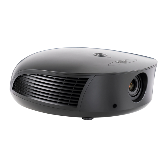
Page 21: Controls And Functions
• EXHAUST VENT Warm air exits the projector through this vent. Ensure that it is not blocked. • INTAKE VENT Internal fans draw cool air into the projector through this vent. Runco LS-10d and LS-10HBd Installation/Operation Manual... - Page 22 (Use it only when the vertical offset is 50% of the screen height or greater.) The light shield attaches to the end of the lens. Runco Logo Badge Rear Cover Lamp Module Cover Cable Opening Ceiling Mount Holes Adjustable Feet Figure 2-2. LS-10 Rear/Bottom/Top View Runco LS-10d and LS-10HBd Installation/Operation Manual...
- Page 23 Use these to attach the ceiling bracket to the projector. Use M4 screws with a maximum screw depth of 10 mm (0.39 inch). • ADJUSTABLE FEET Use these when the projector is installed in a table-top configuration to level the image and/or adjust the projection angle. Runco LS-10d and LS-10HBd Installation/Operation Manual...
-
Page 24: Ls-10 Rear Panel
3. POWER INPUT (100 to 240 VAC) Connect the LS-10 to power here. The other connectors are not used. Connect all signal sources and Note other equipment to the DHD Controller. Runco LS-10d and LS-10HBd Installation/Operation Manual... -
Page 25: Dhd Controller Front Panel
Use to direct-select aspect ratios or move the menu cursor down in the OSD. When no menu is present on-screen, this button toggles through the different aspect ratios, in this order: 16:9 - 4:3 - Letterbox - VirtualWide - Cinema - Virtual Cinema - Native Runco LS-10d and LS-10HBd Installation/Operation Manual... -
Page 26: Dhd Controller Rear Panel
Connection for up to three (3), 12-volt trigger-controlled devices such as retractable screens or screen masks. Output current is limited to 250 milliamperes (mA). 3. USB A standard, USB Series “B” connection to a personal computer, for performing software upgrades and other service procedures. Runco LS-10d and LS-10HBd Installation/Operation Manual... - Page 27 14. HDMI Out (To Display) Connect this to the DHD Input on the LS-10 (see Figure 2-3). 15. RS-232 (PC / Control) A female, 9-pin D-sub connector for interfacing with a PC or automation/control system. Runco LS-10d and LS-10HBd Installation/Operation Manual...
-
Page 28: Remote Control Unit
The following list identifies those buttons that have both standard-mode and extended-mode functions. For more information, refer to Remote Code on page 75 and IR Command List (Extended Mode) on page 98. Figure 2-6. DHD Controller Remote Control Unit for LS-10 Runco LS-10d and LS-10HBd Installation/Operation Manual... - Page 29 2.35:1 screen. In extended mode, press to select the Component input. NATIVE (Standard) / HD 1 Input (Extended) Displays the source signal in its native resolution, centered in the display area. In extended mode, press to select the HD 1 input. Runco LS-10d and LS-10HBd Installation/Operation Manual...
- Page 30 Press this button to exit the current menu and return to the previous one. 9. MENU Press this button to access the OSD controls, or to exit the current menu and return to the previous one. Runco LS-10d and LS-10HBd Installation/Operation Manual...
- Page 31 Video 3 (Composite 3) SRC 7 Component SRC 8 HD 1 SRC 9 SRC 10 HD 2 SCART SRC 11 Not Assigned SRC 12 ... SRC 14 14. 3D Mode Selection Buttons: Not used with the LS-10. Runco LS-10d and LS-10HBd Installation/Operation Manual...
- Page 32 Controls and Functions Notes: Runco LS-10d and LS-10HBd Installation/Operation Manual...
-
Page 33: Installation
• The remote control may fail to operate if the infrared remote sensor is exposed to bright sunlight or fluorescent lighting. • Ambient conditions may possibly impede the operation of the remote control. If this happens, point the remote control at the DHD Controller, and repeat the operation. Runco LS-10d and LS-10HBd Installation/Operation Manual... -
Page 34: Quick Setup
Display calibration: adjust the following for each input and display mode (resolution and frame rate); save settings when finished: • Aspect ratio • Brightness • Contrast • Color level • Tint • Sharpness • White Balance Runco LS-10d and LS-10HBd Installation/Operation Manual... -
Page 35: Installation Considerations
Rear Screen, Floor Mount with Mirror • Projector is completely hidden • Requires separate room • Usually good ambient light rejection • Installation cost is usually higher • Requires less space behind screen than other rear screen installations Runco LS-10d and LS-10HBd Installation/Operation Manual... -
Page 36: Ambient Light
Estimating Throw Distance Throw Distance (TD) = Screen Width (w) x Lens Throw Ratio Figure 3-1. Estimating Throw Distance Runco LS-10d and LS-10HBd Installation/Operation Manual... - Page 37 1. Due to normal manufacturing variances, throw distance can vary by up to +/- 5 percent from these specifications. 2. Only the Proteus 2, 3, 4, 5 and 6 lenses can be used with the optional anamorphic lens. Doing so affects the throw distances as shown here. Runco LS-10d and LS-10HBd Installation/Operation Manual...
-
Page 38: Vertical And Horizontal Position
(1.0 x H) Note: This is a general example of lens shift. Lenses vary in their shift capabilities. No particular lens or projector is used in this example. Figure 3-3. Vertical Lens Shift (EXAMPLE ONLY) Runco LS-10d and LS-10HBd Installation/Operation Manual... -
Page 39: Horizontal Lens Shift (Example Only)
(left or right). For example, with a 96 x 54-inch (16:9) screen, you can shift the image up to 28.80 inches (73.15 cm) left or right of the screen center. (Horizontal lens shift is not possible with the Proteus 1 lens.) Runco LS-10d and LS-10HBd Installation/Operation Manual... -
Page 40: Folded Optics
In order to easily solve this issue, Runco recommends using the DHD Controller with a high-quality audio receiver that has the ability to effectively synchronize audio and video signals. -
Page 41: Other Considerations
Package Contents shipped with your projector may differ slightly from what is shown in these instructions. If any items are missing or damaged, please contact your Runco dealer or Runco Customer Service at (800) 23RUNCO. • Transport Assembly Attachment Plate •... - Page 42 1. Place the projector upside down on a blanket or other soft surface. 2. Position the attachment plate as shown here. Attachment Points for Security Hooks Attachment Points for Transport Assembly Attachment Plate and Ceiling Mount Plate Runco LS-10d and LS-10HBd Installation/Operation Manual...
- Page 43 Attachment Points for Security Hooks Hardware for Attachment Plate and Ceiling Mount Plate (4 Places): Screw, Phillips PH, M4 x 30mm Lock Washer Ceiling Mount Plate Flat Washer Attachment Plate 5/8" Nylon Spacer Projector (bottom) Runco LS-10d and LS-10HBd Installation/Operation Manual...
- Page 44 4. Separate the Anamorphic Lens and lens bracket. Locate the lens bracket mounting screws and use them to attach the bracket to the transport assembly. Observe the sticker on the plate showing the correct sequence for installing and tightening the screws. Runco LS-10d and LS-10HBd Installation/Operation Manual...
- Page 45 2. Use pliers to bend the closed hooks apart just enough to install a Chain End at a later time. 3. Attach the plate hooks to the ceiling as described in the section entitled Ceiling Mounting (Inverted), on the next page. Runco LS-10d and LS-10HBd Installation/Operation Manual...
-
Page 46: Mounting The Ls-10
(Inverted) space for projector and audience, you can invert the LS-10 and suspend it from the ceiling using a specially-designed ceiling mount fixture. Use only the Runco-approved ceiling mount kit designed for your Note projector. Install the ceiling mount kit according to the instructions provided with it. -
Page 47: Adjusting The Projection Angle
Figure 3-6. Mounting Angle Ranges (Front-to-Back and Side-to-Side) If you do this, you may need to shift the image using the on-screen display (OSD) controls, to compensate. For detailed instructions, refer to Primary Lens Adjustments on page 42. Runco LS-10d and LS-10HBd Installation/Operation Manual... -
Page 48: Connections To The Ls-10 And Dhd Controller
• Ensure that the cables are securely connected. Tighten the thumbscrews on connectors that have them. Connector Panel Access Using a flat-blade screwdriver, loosen the two screws holding the rear compartment cover in place. Then, remove the rear compartment cover by tilting it upward. Runco LS-10d and LS-10HBd Installation/Operation Manual... -
Page 49: Connecting The Dhd Controller To The Ls-10
To Display Video 1 Video 2 RS-232 Video 3 PC / Control HDMI Out HDMI 2 HDMI 4 Ethernet Audio Only HDMI Out To Display Figure 3-7. Connecting the LS-10 to the DHD Controller Runco LS-10d and LS-10HBd Installation/Operation Manual... -
Page 50: Connecting Source Components To The Dhd Controller
HDMI 2 HDMI 4 Ethernet Ethernet Audio Only Audio Only HDMI HDMI AV OUT AV OUT HDMI HDMI AV OUT AV OUT HDMI sources (BD, DVD, DTV Set-Top Box etc.) Figure 3-8. HDMI Source Connections Runco LS-10d and LS-10HBd Installation/Operation Manual... -
Page 51: Component Video Source Connections
HD1, HD2 and/or Component/SCART inputs as shown in Figure 3-9. TRIGGERS TRIGGERS Component / SCART Video 1 Video 1 Video 2 Video 2 Video 3 Video 3 RCA-to-BNC adapter COMPONEN T VIDEO OUT DTV-Set-Top Box (DTV-STB) BD/DVD Figure 3-9. Component Video Source Connections Runco LS-10d and LS-10HBd Installation/Operation Manual... -
Page 52: Rgbhv Source Connections
Installation RGBHV Source Connections: Connect personal computers and/or other RGB sources to the HD1 and/or HD2 inputs as shown in Figure 3-10. RGB Camcorder Computer Figure 3-10. RGBHV Source Connections Runco LS-10d and LS-10HBd Installation/Operation Manual... -
Page 53: Scart Rgbs Source Connections
SCART source to the Video 1 input on the DHD Controller. See Figure 3-11. TRIGGERS TRIGGERS Component / SCART Video 1 Video 2 Video 2 Video 3 Video 3 SCART-to-RGBS adapter Green DVD/DTV STB Blue Sync Gaming Console Figure 3-11. SCART RGBS Source Connections Runco LS-10d and LS-10HBd Installation/Operation Manual... -
Page 54: Controller Connection
Audio Only 2 Receive Data (to ctrl. system) to Automation/ 3 Transmit Data Control System (from ctrl. system) or PC 5 Ground (none of the other pins are used) Figure 3-13. RS-232 Control System Connection Runco LS-10d and LS-10HBd Installation/Operation Manual... -
Page 55: Connecting 12-Volt Trigger Outputs To External Equipment
You can also use a 12-volt trigger output on the DHD Controller to Note control the lens transport; however, you must manually configure it for this purpose. Refer to Configure Lens Motor Trigger on DHD Controller (Optional) on page 45 for more information. Runco LS-10d and LS-10HBd Installation/Operation Manual... -
Page 56: Connecting An External Ir Receiver To The Dhd Controller
To Pri. Display To Pri. Display to Ethernet 1 Transmit Data + Hub, Router 2 Transmit Data - or Gateway 3 Receive Data + 6 Receive Data - Figure 3-17. Ethernet Network Connection to DHD Controller Runco LS-10d and LS-10HBd Installation/Operation Manual... -
Page 57: Connecting To Ac Power
4. When the projector is ready for use, the fluorescent display indicates the active source, input resolution/frame rate and aspect ratio; for example: Current Source HDMI 1 LS-10 16:9/1 1080i/60 Aspect Ratio/Screen Input Resolution/Frame Rate Runco LS-10d and LS-10HBd Installation/Operation Manual... -
Page 58: Primary Lens Adjustments
Note 3. Select Display Device from the Service Menu. 4. Select Configure from the Display Device menu, then select Installation. 5. Select Orientation, then choose Floor/Rear, Ceiling/Front or Ceiling/Rear, to match the installation method. Runco LS-10d and LS-10HBd Installation/Operation Manual... -
Page 59: Adjusting The Image Geometry
Use these controls as (and only if) needed to re-position the image corners, mid-points and center to eliminate “keystoning” (mis-aligned corners) or “pincushion” distortion (mid-points not aligned with corners). See Figure 3-18. Horizontal Keystoning Vertical Keystoning Pincushion Distortion Figure 3-18. Keystone and Pincushion Distortion Runco LS-10d and LS-10HBd Installation/Operation Manual... -
Page 60: Image Alignment Controls
1. Smaller “x” values move a point to the left; larger values move it to the right. 2. Smaller “y” values move a point up; larger values move it down. Figure 3-19. Image Alignment Controls Runco LS-10d and LS-10HBd Installation/Operation Manual... -
Page 61: Installing And Adjusting The Anamorphic Lens
2. On the DHD Controller remote control or front panel, press MENU. 3. Select Service from the Main Menu and enter the Service Menu passcode. You must enter a passcode to access the Service menu for the first Note time after turning on the system. Runco LS-10d and LS-10HBd Installation/Operation Manual... - Page 62 Note properly adjusted, especially at shorter throw distances. If this is the case, Runco recommends that you slightly over-scan the image into the screen frame area to mask the distortion. 3. Adjust the rotation of the Lens Transport Assembly so that the left and right sides of the image are an equal distance from their respective screen borders.
-
Page 63: Operation
5, 6, 7 ... 15 ... 59, 60 Manufacturing Splash Enable On/Off OSD Position Hor. / Ver. 0, 1, 2 ... 100 Note: Default settings appear in bold type. Figure 4-1. DHD Controller OSD Menu Structure for LS-10 Runco LS-10d and LS-10HBd Installation/Operation Manual... -
Page 64: Dhd Controller Osd Menu Structure For Ls-10
On / Off Auto Power Off Hours 1, 2, 3, 4, ... 8 ... 23, 24 Standby Mode Low Power / Fast Startup System Reset Figure 4-1. DHD Controller OSD Menu Structure for LS-10 (continued) Runco LS-10d and LS-10HBd Installation/Operation Manual... -
Page 65: Main Menu
Most modern DVD/BD players and set-top boxes have such controls. • Viewer preference (original aspect ratio with “black bars,” or a full-screen presentation with some distortion or cropping). The aspect ratio selection is automatically saved for each input and Note resolution. Runco LS-10d and LS-10HBd Installation/Operation Manual... - Page 66 4:3 Image on 16:9 Screen (Display) screen. 4:3 Image on 16:9 Screen with VirtualWide On a 2.35:1 screen, the image is 4:3 Image on centered between black bars on 2.35:1 Screen with VirtualWide either side. Runco LS-10d and LS-10HBd Installation/Operation Manual...
- Page 67 320 on the left and right sides and 180 above and below. 720p HDTV Image With SDTV and EDTV sources, the DHD Controller scales the image horizontally to achieve a 16:9 aspect ratio. Runco LS-10d and LS-10HBd Installation/Operation Manual...
-
Page 68: Screen
Color implemented a training program for technicians and installers to use these standards to obtain optimal picture quality from Runco video display devices. Accordingly, Runco Tint recommends that setup and calibration be performed by an ISF certified installation Sharpness technician. - Page 69 Select Contrast and press ENTER. Adjust the contrast to a point just below which the white rectangle starts to increase in size. Brightness and contrast controls are interactive. A change to one Note may require a subtle change to the other in order to achieve the optimum setting. Runco LS-10d and LS-10HBd Installation/Operation Manual...
- Page 70 7. Select Blue from the Diagnostics menu, then press ENTER to display only the blue color channel. 8. Press EXIT (or MENU) repeatedly to return to the Main Menu. 9. Select Picture from the Main Menu and press ENTER. 10.Select Color from the Picture menu and press ENTER. Runco LS-10d and LS-10HBd Installation/Operation Manual...
- Page 71 Like the brightness and contrast controls, the color and tint controls Note are interactive. A change to one may require a subtle change to the other in order to achieve the optimum setting. Runco LS-10d and LS-10HBd Installation/Operation Manual...
-
Page 72: Input Position
Press to shift the image upward; press to shift it downward. Width: Select Width from the Input Position menu to change the projected image width. Press to increase the width; press to decrease it. Runco LS-10d and LS-10HBd Installation/Operation Manual... -
Page 73: Overscan Modes
5% on all sides or 10% total. Figure 4-6 illustrates the effect of each overscan mode setting. Crop Zoom 16:9 = Source Image Area = Edge Noise = Screen (16:9) Figure 4-6. Overscan Modes Runco LS-10d and LS-10HBd Installation/Operation Manual... -
Page 74: Memory Presets
Use the Memory Presets menu to recall saved image presets, or to save image settings in the “Custom 1” or “Custom 2” memory location. The currently-selected preset is indicated by a “ ” to its left; in the example shown here, ISF Night is selected. Runco LS-10d and LS-10HBd Installation/Operation Manual... -
Page 75: Sleep Timer
Select Sleep Timer from the Main Menu to turn off the LS-10 after a specified interval. Sleep Timer Press to select Off, 30 Minutes, 60 Minutes, 90 Minutes, 2 Hours or 4 Hours. Then, press ENTER. Sleep Timer 30 Minutes 60 Minutes 90 Minutes 2 Hours 4 Hours Runco LS-10d and LS-10HBd Installation/Operation Manual... -
Page 76: Information
Information your DHD Controller and display device. Signal System Should you ever need to contact Runco Technical Support, this information will help them Network answer your questions or resolve product performance issues. Field Service Manufacturing... -
Page 77: Calibration
Advanced. Then, select Advanced from the Gamma menu to select one of up to 20 pre-programmed gamma tables. Custom gamma tables provide the ability to perform complex, non-linear gamma correction on each primary color channel independently of the others. Runco LS-10d and LS-10HBd Installation/Operation Manual... - Page 78 Table 4-2 lists the x- and y-coordinates for each color temperature preset. Table 4-2. Color Temperature Presets and Associated Color Points Associated x/y Values Color Temperature Preset 5500K 0.332 0.348 6500K 0.313 0.329 7500K 0.299 0.315 9300K 0.284 0.298 Runco LS-10d and LS-10HBd Installation/Operation Manual...
- Page 79 0.419 0.505 0.421 0.507 0.418 0.502 Green 0.300 0.600 0.310 0.595 0.290 0.600 Cyan 0.225 0.329 0.231 0.326 0.220 0.329 Blue 0.150 0.060 0.155 0.070 0.150 0.060 Magenta 0.321 0.154 0.314 0.161 0.328 0.158 Runco LS-10d and LS-10HBd Installation/Operation Manual...
- Page 80 When both boxes are checked, the DHD Controller automatically displays a red, green, blue, yellow, cyan, magenta or white “curtain” test pattern when you select an x- or y-value for that color point to adjust. Runco LS-10d and LS-10HBd Installation/Operation Manual...
- Page 81 Display Color - Projector Settings menu to enable (On) or disable (Off) ConstantContrast in the optical engine. ConstantContrast uses a dynamic iris that modulates light to the DMD based on the actual content of the video material. Runco recommends that you disable ConstantContrast before adjusting Brightness, Contrast or other image settings.
- Page 82 Then, select Paste Settings from the Copy/Paste Memory Preset menu. If you want to keep these new settings, you must save them! (Refer to Save ISF Night/Save ISF Day on page 66 or Memory Presets on page 58.) Runco LS-10d and LS-10HBd Installation/Operation Manual...
- Page 83 30 characters in length. Use the up or down cursor button to select a character. Use the right and left cursor buttons to change the cursor position. Press MENU when you have finished entering text. Runco LS-10d and LS-10HBd Installation/Operation Manual...
-
Page 84: Service
• Splash Timer: When you turn on the LS-10, it projects a welcome screen with the Runco and ISF logos, along with the personalized information you enter as described above. Select Splash Timer from the Splash Configure menu to set the amount of time for which this screen appears. - Page 85 Refer to Primary Lens Adjustments on page 42. • Display Info.: Select Display Info. from the Display Device - Configure menu to obtain information about the currently-installed lamp: its serial number and number of hours in use. Runco LS-10d and LS-10HBd Installation/Operation Manual...
- Page 86 IP gateway. The procedure is similar to that for setting the IP address. • Communication Test: Select Communication Test from the IP Configuration menu to verify proper operation of the network communication link. Runco LS-10d and LS-10HBd Installation/Operation Manual...
- Page 87 Yes to perform the upgrade or No to return to the previous menu. • E-Mail Notification: Select E-Mail Notification from the Network menu to specify when and to whom the DHD Controller sends error and service notification messages via e-mail. Runco LS-10d and LS-10HBd Installation/Operation Manual...
- Page 88 “DHD Error” or “Display Error” occurs, select Error Notification from the E-Mail Notification menu and set it to On. • Error Notification to Runco: To have the DHD Controller send an e-mail message to Runco Customer Support when a “DHD Error” or “Display Error” occurs, select Error Notification to Runco from the E-Mail Notification menu and set it to On.
- Page 89 Set it to On to allow all incoming remote network connectivity. Set it to Off to disable any incoming network communication that was not initiated by the DHD Controller. This setting has no effect on the E-Mail Notification or Auto Note Firmware Upgrade functions. Runco LS-10d and LS-10HBd Installation/Operation Manual...
- Page 90 • Blank Screen Color: Select Blank Screen Color from the Miscellaneous menu to select the color that appears when no incoming signal is present. The range is from 0 to 255 inclusive for each color component (red, green and blue). Runco LS-10d and LS-10HBd Installation/Operation Manual...
- Page 91 Use the DHD Controller front-panel keypad to change the IR code to which the controller will respond. Then, change the code sent by the remote to match as described below. After changing the Remote Code, press EXIT to have the new code take effect. Runco LS-10d and LS-10HBd Installation/Operation Manual...
- Page 92 If the sync level from the source is persistently too low, the display device won’t sync with the source at all. The range is from 0 (approximately 60 millivolts (mV)) to 15 (approximately 300 mV). Runco LS-10d and LS-10HBd Installation/Operation Manual...
- Page 93 HDMI device (third-party display or audio/video receiver). The default setting, Auto, disables HPD toggle rejection on the LS-10. Use the other settings to troubleshoot compatibility issues or reduce the amount of time needed to lock to an incoming signal. Runco LS-10d and LS-10HBd Installation/Operation Manual...
- Page 94 A confirmation message appears. Select Yes to continue with the reset or select No to cancel. This action is not undoable. Proceed with caution! Before you Caution perform a System Reset, save your “Custom” Memory Presets (page 58) and ISF Day/Night Memory Presets (page 66). Runco LS-10d and LS-10HBd Installation/Operation Manual...
-
Page 95: Maintenance And Troubleshooting
4000 hours depending on the Lamp Power setting), or sooner if a noticeable Lamp Replacement degradation in brightness occurs. Contact your Runco dealer to obtain a replacement lamp. 1. Turn off the projector and unplug the power cord. Allow the projector to cool down for approximately 60 minutes prior to removing the lamp assembly for replacement. -
Page 96: Troubleshooting Tips
LED at the front of the down, or the image disap- power-down, to protect DHD Controller turns red. pears during operation. the lamp. • The lamp has failed. • Replace the lamp. Runco LS-10d and LS-10HBd Installation/Operation Manual... -
Page 97: External Control
Runco products (manufactured prior to September 2011) that include the DHD Controller. Runco recommends using this new protocol, as it is more concise and provides greater control than the old one. However, to maintain backward compatibility with existing automation/control system modules, the legacy Runco serial protocol is also supported. -
Page 98: Command Format
• 6 = Setting value not supported • 7 = String too long • 8 = Command not supported in standby mode • 9 = Invalid parameter • 10 = Error processing command • 11 = Password not entered Runco LS-10d and LS-10HBd Installation/Operation Manual... -
Page 99: Command And Response Examples
6 = Magenta PCE Blue x -100 PCE Blue y -100 PCE Green x -100 PCE Green y -100 Apply Image Alignment Values 0 = Off; 1 = On Altitude 0 = Auto 1 = High Runco LS-10d and LS-10HBd Installation/Operation Manual... - Page 100 1 = On CEC Enable 0 = Off; 1 = On Chroma Delay Color Gamut 0 = Auto 1 = REC709 2 = SMPTE C 3 = EBU 4 = Native 6 = PCE Runco LS-10d and LS-10HBd Installation/Operation Manual...
- Page 101 Display Green Gain -100 Display Green Offset -100 DHCP 0 = Off; 1 = On Display Red Gain -100 Display Dark Interval Var. Var. Display Red Offset -100 Error Notification 0 = Off; 1 = On Runco LS-10d and LS-10HBd Installation/Operation Manual...
- Page 102 2 = HDMI Out 2 HDMI EDID Extension 1 0 = Off; 1 = On HDMI EDID Extension 2 HDMI EDID Extension 3 HDMI EDID Extension 4 HPD Toggle Rejection 0 = Off; 1 = On Runco LS-10d and LS-10HBd Installation/Operation Manual...
- Page 103 Information Copied Input Source Information Copied Memory Pre- Information Copied Screen Information Copied Signal Format Information Display Name Information Firmware Version Input Green Gain Input Green Offset Information Horizontal Frequency Information Input Resolution information Micro Version Runco LS-10d and LS-10HBd Installation/Operation Manual...
- Page 104 Input Position Up Down Input Position Width Input Red Gain Input Red Offset Information Signal Format Information Serial Number Information Sync Type 0 = None 1 = Separate 2 = Composite 3 = Sync-on-green Information Vertical Frequency Runco LS-10d and LS-10HBd Installation/Operation Manual...
- Page 105 5 = Portuguese 6 = Simplified Chinese 7 = Traditional Chinese 8 = Swedish 9 = Russian 10 = Japanese 11 = Korean Lens Home Position Action will be performed on any setting value Runco LS-10d and LS-10HBd Installation/Operation Manual...
- Page 106 0 = Off; 1 = On OSD Timer Values from 1-4 are not allowed; if increment or decrement is used, these values will be skipped. Output Shift Up Down -200 OSD Position Vertical Output Shift Width Runco LS-10d and LS-10HBd Installation/Operation Manual...
- Page 107 0 = Off; 1 = On Standby LED Enable 0 = Off; 1 = On Splash Configure String 1 Splash Configure String 2 30 characters max Splash Configure String 3 Sidebar Color Blue Sidebar Color Green Runco LS-10d and LS-10HBd Installation/Operation Manual...
- Page 108 4 = 2 Hours 5 = 4 Hours Subnet Mask Byte 1 Subnet Mask Byte 2 Subnet Mask Byte 3 Subnet Mask Byte 4 System Reset Action will be performed on any setting value Runco LS-10d and LS-10HBd Installation/Operation Manual...
- Page 109 -100 Tint Offset Picture menu Tint Calibration -> Input Color menu Test Pattern Enable 0 = Off; 1 = On Tracking -100 Image Alignment Top Right x -100 Image Alignment Top Right y -100 Runco LS-10d and LS-10HBd Installation/Operation Manual...
- Page 110 VFD Text Line 2 24 characters max VFD Brightness 0 = 0% 1 = 25% 2 = 50% 3 = 75% 4 = 100% (VSH+) (VSH-) Vertical Shift Send adjust incrementally (ZOM+) (ZOM-) Zoom Send adjust incrementally Runco LS-10d and LS-10HBd Installation/Operation Manual...
-
Page 111: Using Discrete Ir Codes
0 0 0 0 0 0 0 0 1 0 0 0 1 0 0 0 0 0 0 0 1 9 ms 4.5 ms 13.5 ms 27 ms 27 ms Figure 6-1. NEC Protocol Message Format Runco LS-10d and LS-10HBd Installation/Operation Manual... -
Page 112: Ir Command List (Standard Mode)
EXIT 8209 0x20111CE3 Up-Arrow ( Note: These codes assume that the default address of 8209 is used. If you change it to something other than 8209, you will need to modify these codes accordingly. Runco LS-10d and LS-10HBd Installation/Operation Manual... - Page 113 8209 0x20114EB1 HDMI4 video input Note: These codes assume that the default address of 8209 is used. If you change it to something other than 8209, you will need to modify these codes accordingly. Runco LS-10d and LS-10HBd Installation/Operation Manual...
-
Page 114: Ir Command List (Extended Mode)
0x201156A9 Composite video input 3 Note: These codes assume that the default address of 8209 is used. If you change it to something other than 8209, you will need to modify these codes accordingly. Runco LS-10d and LS-10HBd Installation/Operation Manual... -
Page 115: Using Hdmi Cec Messages
– √ Inactive Source 0x9D – √ CEC Version 0x9E – √ Set OSD Name 0x47 – √ Menu Status 0x8E – √ Report Power Status 0x90 – √ Set Menu Language 0x32 – Runco LS-10d and LS-10HBd Installation/Operation Manual... - Page 116 Give OSD Name 0x46 – √ Menu Request 0x8D – √ Give Device Power Status 0x8F – The DHD Controller does not transmit HDMI CEC control Note messages from the “HDMI Audio Out” connector. Runco LS-10d and LS-10HBd Installation/Operation Manual...
-
Page 117: Specifications
(from DHD Controller): (1) RS-232 Power Requirements: 100 to 240 VAC (auto-sensing), 50/60 Hz, 400 Watts (1365.2 BTUs/hour) Operating Environment: 50°F to 104°F (10°C to 40°C), 0% to 85% humidity (non-condensing) Dimensions: See Figure 7-1 Runco LS-10d and LS-10HBd Installation/Operation Manual... - Page 118 Contrast Ratio: 1,200:1 full-on, full-off These are typical projector brightness and contrast specifications found in most companies’ sales literature. Runco includes these measurements in its literature to allow for direct comparison with other manufacturers’ projectors. These measurements are typically taken at 9,000K to 13,000K to get expected performance data when the projector is used in professional, commercial and industrial displays.
-
Page 119: Dhd Controller Specifications
Weight: 13.0 lbs. (5.90 kg) Regulatory Approvals: Complies with FCC, CE C-Tick Limited Warranty: Two (2) years parts and labor from the date of shipment from Runco. Specifications are subject to change without notice. Runco LS-10d and LS-10HBd Installation/Operation Manual... -
Page 120: Ls-10 Dimensions
5.91 M4-.7 (MAX 10mm WITHOUT FIX PLATE) 99.9 3.93 44.0 2X Ø 1.73 160.0 99.2 6.30 519.9 3.91 20.47 259.9 10.23 179.9 7.08 99.9 3.93 15.0 139.6 327.4 5.50 12.89 Figure 7-1. LS-10 Dimensions Runco LS-10d and LS-10HBd Installation/Operation Manual... -
Page 121: Supported Timings
√ √ √ 75.00 60.289 102.250 – – √ √ √ 85.00 68.633 117.500 – – √ √ √ 60.00 60.000 108.000 – – 1280x960 1280x960 √ √ √ 85.00 85.938 148.500 – – Runco LS-10d and LS-10HBd Installation/Operation Manual... - Page 122 – – √ NTSC 3.58 – 59.94/60.00 15.734/15.750 3.580 – – – – √ NTSC 4.43 – 59.94/60.00 15.734/15.750 4.430 – – – – √ PAL-B/G/H/I – 50.00 15.625 4.430 – – – – Runco LS-10d and LS-10HBd Installation/Operation Manual...
- Page 123 Rate (Hz) (MHz) (kHz) √ PAL-M – 59.94/60.00 15.734/15.750 3.580 – – – – √ PAL-N – 50.00 15.625 3.580 – – – – √ √ SECAM – 50.00 15.625 13.500 – – – Runco LS-10d and LS-10HBd Installation/Operation Manual...
- Page 124 Specifications Notes: Runco LS-10d and LS-10HBd Installation/Operation Manual...
- Page 126 020-1073-01 Rev. A September 2012 Runco International • (800) 23RUNCO • Fax (503) 748-8161 • www.runco.com...
Need help?
Do you have a question about the LightStyle LS-10d and is the answer not in the manual?
Questions and answers