
Subscribe to Our Youtube Channel
Related Manuals for Grizzly G0661


Summary of Contents for Grizzly G0661
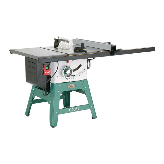
- Page 1 MODEL G0661 10" CONTRACTOR TABLE SAW with RIVING KNIFE OWNER'S MANUAL WARNING: NO PORTION OF THIS MANUAL MAY BE REPRODUCED IN ANY SHAPE OR FORM WITHOUT THE WRITTEN APPROVAL OF GRIZZLY INDUSTRIAL, INC.
-
Page 3: Table Of Contents
INTRODUCTION ... 2 SECTION 1: SAFETY ... 7 SECTION 2: CIRCUIT REQUIREMENTS ... 12 SECTION 3: SETUP ... 13 SECTION 4: OPERATIONS ... 23 Table of Contents SECTION 5: ACCESSORIES ... 39 SECTION 6: MAINTENANCE ... 43 SECTION 7: SERVICE ... 45 SECTION 8: WIRING ... -
Page 4: Introduction
INTRODUCTION Manual Accuracy Functional Overview your machine may not exactly match the manual www.grizzly.com Contact Info... - Page 5 Identification Figure 1.
-
Page 6: Machine Data Sheet
Customer Service #: (570) 546-9663 · To Order Call: (800) 523-4777 · Fax #: (800) 438-5901 MODEL G0661 10" 2 HP CONTRACTOR STYLE TABLE SAW Weight... 292 lbs. Length/Width/Height... 66 x 40 x 40-1/2 in. Foot Print (Length/Width)... 26-1/4 x 26 in. - Page 7 Maximum Blade Diameter... 10 in. Maximum Width Of Dado... 3/4 in. Blade Tilt... Left 0-45 deg. Arbor Size...5/8 in. Arbor Speed... 4200 RPM Arbor Bearings... Sealed and Permanently Lubricated Rim Speed...1904 FPM Maximum Depth Of Cut At 90 Degrees...3-1/8 in. Maximum Depth Of Cut At 45 Degrees...2-1/4 in.
- Page 8 ISO Factory ... ISO 9001 Country Of Origin ... China Warranty ... 1 Year Serial Number Location ... ID Label on Cabinet Assembly Time ... 1 hour Riving Knife Camlock T-Shaped Fence with Aluminum Fence Extension Rails Available to Rip 36" Wide Includes Regular as well as Dado Blade Inserts Precision Ground Cast Iron Table with Beveled Edge All Machined Cast Iron Internal Structure...
-
Page 9: Safety Instructions For Machinery
Safety Instructions for Machinery... -
Page 11: Safety Instructions For Table Saws
Until you have a clear understanding of kickback and how it occurs, DO NOT oper- ate this table saw! REACHING OVER SAW BLADE. hands or arms will be pulled into the saw blade if kickback occurs. WORKPIECE CONTROL. SAFETY ACCESSORIES. OPERATOR POSITION. CUT-OFF PIECES. -
Page 12: Preventing Kickback
Kickback is typically defined as the high-speed expulsion of stock from the table saw toward its opera- tor. In addition to the danger of the opera- tor or others in the area being struck by the flying stock, it is often the case that the operator’s hands are pulled into the... -
Page 13: Glossary Of Terms
Glossary of Terms Arbor: Bevel Edge Cut: Blade Guard Assembly: Crosscut: Dado Blade: DO NOT use a dado blade larger than 8" in diameter on this saw! Dado Cut: Page 31 Featherboard: Page 42 Kerf: Kickback: VERY Non-Through Cut: Page 28... -
Page 14: Section 2: Circuit Requirements
Compliance MUST be verified by a qualified electrician! NOTICE The Model G0661 is prewired for 110V. If you plan to operate the machine at 220V, the motor must be rewired (see Page 56) and a 220V plug must be installed. -
Page 15: Section 3: Setup
SECTION 3: SETUP Setup Safety This machine presents serious injury hazards to untrained users. Read through this entire manu- al to become familiar with the controls and opera- tions before starting the machine! Wear safety glasses dur- ing the entire setup pro- cess! This machine and its com- ponents are very heavy. - Page 16 Inventory Note: If you can't find an item on this list, check the mounting location on the machine or examine the packaging materials carefully. Occasionally we pre-install certain components for shipping. Box Contents (Figures 3–5) Hardware (Not Shown) Figure 3. Figure 4.
-
Page 17: Hardware Recognition Chart
Hardware Recognition Chart... -
Page 18: Site Considerations
Clean Up Figure 6 For optimum performance, clean all moving parts or sliding contact surfaces. Gasoline and petroleum products have low flash points and can explode or cause fire if used to clean machinery. NOT use these products to clean the machinery. Many cleaning solvents toxic Minimize your risk by only... - Page 19 To assemble the table saw: Figure 8. Step 1 Figure 9 Make sure the upper stand brace with the Grizzly logo is on the same side as the lower stand brace with the G0661 label. Figure 9. Figure 8 Figure 10.
- Page 20 Figure 12. Figure 13 Figure 13. Figure 12 Figure 14. Figure 15. Figure 14 Figure 15...
- Page 21 Figure 16 Note: After reinstalling wings, remove all excess masking tape with a razor blade. Figure 16. Figure 17 Figure 17. Figure 18 Figure 18. Figure 19 Figure 19. Figure 20. Page 21 Figure 21. Figure 20...
- Page 22 Note: It's permissible for the back of the fence to pivot outward not more than being parallel to the blade. This creates a slightly larger opening between the fence and the blade, at the rear of the blade, to reduce the risk of workpiece binding or burning as it is fed through the cut.
-
Page 23: Dust Collection
Figure 25 Figure 25. Figure 26. Dust Collection DO NOT operate the Model G0661 without an adequate dust collection system. This saw creates substantial amounts of wood dust while operating. Failure to use a dust collec- tion system can result in short and long-term respiratory illness. -
Page 24: Recommended Adjustments
Test Run Troubleshooting Page 45 To test run the machine: Figure 28. Recommended Adjustments Adjustments that should be verified: Figure 28 SECTION 7: SERVICE Page 47 Page 48 Page 49... -
Page 25: Section 4: Operations
OMMEND that you read books, trade maga- zines, or get formal training before begin- ning any projects. Regardless of the con- tent in this section, Grizzly Industrial will not be held liable for accidents caused by lack of training. Basic Controls ON/OFF Switch: Safety Pin &... -
Page 26: Blade Selection
Blade Height Fence Lock: Blade Selection Ripping blade features: Figure 31. Crosscut blade features: Figure 32. Combination blade features: Figure 33. Laminate blade features: Figure 34. -
Page 27: Blade Installation
Stacked Dado Blade Figure 35. Wobble Dado Blade Thin Kerf Blade: Blade Installation The saw blade is extremely sharp. Use extra care or wear gloves when handling the blade or working near it. To install the blade: Figure 35 Note: The arbor nut has right hand threads;... -
Page 28: Blade Guard Assembly
NOTICE Some thin-kerf blades may be thinner than the thickness of the splitter. DO NOT install these blades on the saw, because the workpiece will hit the splitter during opera- tion, possibly causing kickback. Always make sure the kerf of a blade you install is not thinner than the splitter. -
Page 29: Riving Knife
NOTICE Some thin-kerf blades may be thinner than the thickness of the riving knife. DO NOT install these blades on the saw, because the workpiece will hit the riving knife dur- ing operation, possibly causing kickback. Always make sure the kerf of a blade you install is not thinner than the riving knife. -
Page 30: Workpiece Inspection
Workpiece Inspection Before cutting, inspect all workpieces for the following: Material Type: Foreign Objects: Large/Loose Knots: Wet or "Green" Stock: Excessive Warping: Minor Warping: Non-Through & Through Cuts Non-Through Cuts Figure 40 Figure 40. Through Cuts Figure 41 Figure 41. - Page 31 Page 10 Figure 42. Turn OFF the saw and allow the blade to come to a complete stop before removing the cut-off piece. Failure to follow this warn- ing could result in serious personal injury.
-
Page 32: Miter Cuts
To make a crosscut using the miter gauge: Figure 43 Figure 43. Turn OFF the saw and allow the blade to come to a complete stop before removing the cut-off piece. Failure to follow this warn- ing could result in serious personal injury... -
Page 33: Dado Cutting
Using a Stacked or Wobble Dado Blade DO NOT use a dado blade larger than 8" in diameter on this saw! The danger of kickback increases relative to the depth and width of a cut. Reduce the risk of kickback by making multiple shal- low cuts to achieve the desired depth of cut. - Page 34 ALWAYS replace the blade guard after dadoing is complete. Figure Using a Standard Saw Blade to Cut...
-
Page 35: Rabbet Cutting
Note: Rabbet cutting requires the use of a sacrifi- cial fence attachment, as shown in Figure 49. Cutting Rabbets with Dado Blade DO NOT use a dado blade larger than 8" in diameter on this saw! Figure 49 Figure 49. -
Page 36: With Standard
Note: Include marks on the edge of the workpiece to clearly identify the intended cut while it is laying flat on the saw table. The danger of kickback increases relative to the depth of a cut. Reduce the risk of kick- back by making multiple passes to achieve the desired depth of cut. - Page 37 Failure to follow these warnings could result in serious personal injury. are ideal for resawing and the process is fairly easy and safe. A table saw is not intended for resawing and the process is difficult and extremely dangerous.
-
Page 38: Auxiliary Fence
Resaw Barrier Figure 53 Figure 53. Components Needed for the Resaw Barrier: Tools Needed for the Resaw Barrier: To build the resaw barrier: Note: Only use furniture grade plywood or kiln dried hardwood to prevent warping. Figure 54. Step 2 Auxiliary Fence Components Needed for the Auxiliary Fence: Tools Needed for the Resaw Barrier:... -
Page 39: Resawing Operations
Step 4 Step 5 Figure 55 Figure 55. Resawing Operations Components Needed for Resawing: You may experience kickback during this procedure. Stand to the side of the blade and wear a full face shield to prevent injury when resawing. To perform resawing operations: Note: When figuring out the correct width, don't forget to account for blade kerf and the inaccuracy of the fence scale while the auxil-... - Page 40 Always use push sticks or push paddles to increase safety and control during opera- tions which require that the blade guard and splitter must be removed from the saw. ALWAYS replace the blade guard after resawing is complete. Figure 57. Steps 6–8...
-
Page 41: Section 5: Accessories
SECTION 5: ACCESSORIES Aftermarket Accessories H7583—Grizzly Tenoning Jig Figure 58 T20392—Success with Tablesaws Figure 59. Carbide-Tipped ATB Circular Saw Blades H9144—10" Ripping Blade, 30T H9145—10" General Purpose, 40T H9146—10" Fine Finishing/Cabinet Work, 60T H9147—10" Cabinet Work/Trimming, 80T H9148—10" Super Fine Work/Trimming, 100T Figure 60. - Page 42 H7777—Grizzly 8" Stack Dado Set Figure 62. G2370— Board Buddies-Yellow Figure 63. T20501—Face Shield Crown Protector 4" T20502—Face Shield Crown Protector 7" T20503—Face Shield Window T20448—Economy Clear Safety Glasses T20452—"Kirova" Anti-Reflective Glasses T20456—"Dakura" Clear Safety Glasses ® H0736—Shop Fox Safety Glasses...
- Page 43 Gun Treatment 12 oz Spray H3789—G96 ® Gun Treatment 4.5 oz Spray Figure 66. G7314—Heavy-Duty Figure 67. T20818—Zero Clearance Insert for G0661 G7581—Superbar G7582—Master Plate Figure 68. Mobile Base H1049—Clear Flexible Hose 2 H1052—Clear Flexible Hose 4" x 10' G3123—Black Flexible Hose 2 G1536—Black Flexible Hose 4"...
- Page 44 Shop Made Safety Accessories Push Stick Figure 70. Featherboard Figure 71. Outfeed & Support Tables Figure 72. Crosscut Sled Figure 73.
-
Page 45: Section 6: Maintenance
SECTION 6: MAINTENANCE Always disconnect power to the machine before performing maintenance. Failure to do this may result in serious person- al injury. Schedule Daily Check: Weekly Maintenance: Monthly Maintenance: Section 5: Accessories Page 54 Cleaning Page 39... - Page 46 Lubrication Trunnion Slides & Tilt Leadscrew Figure 74 Figure 74. Bevel Gears, Elevation Leadscrew and Rails Page Figure 75. Figure 75 Figure 75...
-
Page 47: Section 7: Service
SECTION 7: SERVICE Troubleshooting Page 54 Page 54... - Page 48 Page 25 Page 48 Page 51 Page 47 Page 47 Page 48 Page 25 Page 51 Page 48...
-
Page 49: Blade Tilt Stops
Blade Tilt Stops Figure 76 Figure 76 Note: The tilt scale reads "0" when the blade is 90° to the table. Tools Needed ° Setting 90° Stop Bolt Figure 77. Figure 77 Figure 78 Figure 78... -
Page 50: Miter Slot To Blade Parallelism
Setting 45° Stop Bolt Figure 79. Miter Slot to Blade Tools Needed Figure 79 To adjust the blade parallel to the miter slot: Figure 80. Parallelism Figure 80. - Page 51 The saw blade is dangerously sharp. Use extra care or wear gloves when handling the blade or working near it. Step 6 Step 7 Steps 2–5 Figure 81. Splitter or Riving Knife Alignment Spreader Thickness Checking Alignment Tools Needed To check the splitter/riving knife alignment: Figure 81 Figure 82.
- Page 52 Knife Shimming Splitter/Riving Knife Note: These instructions require that you complete the Checking Splitter/Riving Knife Alignment instructions first and that the saw is disconnected from power and the blade is raised. Possible Tools Needed To shim the splitter/riving knife: Note: Do not fully remove the mounting bolt...
-
Page 53: Fence Adjustments
Fence Adjustments Tools Needed Square and Height To check/adjust the fence height and square- ness to the table: Figure 85 Step 3 Step 4 Figure 85. Figure 86. Note: If the front end of the fence needs to be adjusted up or down, use the set screws from Figure 86;... - Page 54 Clamping Pressure and Parallelism To adjust the fence clamping pressure and parallelism to the blade: Figure 87 Figure 87. Figure 88 Figure 88 Optional Figure 89 Figure 89.
-
Page 55: Fence Scale Calibration
Fence Scale Calibration Figure 90 Figure 90. Tools Needed To calibrate the fence scale indicator win- dows: Step 2 Miter Gauge Adjustments Tools Needed Checking/Setting 90° Stops Figure 91 Figure 91. -
Page 56: Tensioning Belt
Step 4 Checking/Setting 45° Stops Figure 92. Belt Tension & Replacement Tools Needed Tensioning Belt Figure 93 Figure 93. Figure 92 Replacing Belt Figure 93... -
Page 57: Section 8: Wiring
QUALIFIED ELECTRICIAN. WIRE CONNECTIONS. MOTOR WIRING. The photos and diagrams included in this section are best viewed in color. You can view these pages in color at www.grizzly.com. MODIFICATIONS. WIRE/COMPONENT DAMAGE. CAPACITORS. CIRCUIT REQUIREMENTS. Page 12 9. EXPERIENCING DIFFICULTIES. READ ELECTRICAL SAFETY... -
Page 58: Wiring Diagram
Wiring Diagram MOTOR (Prewired 110V) READ ELECTRICAL SAFETY ON PAGE 55! PUSH BUTTON SWITCH (viewed from behind) MOTOR (Wired 220V) The motor wiring shown here is current at the time of printing; however, always use the diagram on the inside of junction box cover when rewiring your motor. -
Page 59: Section 9: Parts
SECTION 9: PARTS Table Saw Body Breakdown... -
Page 60: Table Saw Body Parts List
Table Saw Body Parts List REF PART # DESCRIPTION P0661003 MITER GAUGE ASSEMBLY PSS07M SET SCREW M5-.8 X 5 P0661005 TABLE INSERT PFH54M FLAT HD SCR M5-.8 X 20 P0661008 EXTENSION TABLE PB09M HEX BOLT M8-1.25 X 20 PLW04M LOCK WASHER 8MM... -
Page 61: Stand Parts Breakdown
Stand Parts Breakdown REF PART # DESCRIPTION PW01M FLAT WASHER 8MM PN03M HEX NUT M8-1.25 PCB11M CARRIAGE BOLT M8-1.25 X 12 P0661099 RIGHT STAND LEG P0661100 UPPER STAND BRACE REF PART # DESCRIPTION P0661101 LOWER STAND BRACE P0661102 SIDE STAND BRACE P0661103 LEFT STAND LEG P0661104... - Page 62 Guard & Switch Breakdown REF PART # DESCRIPTION P0661002 BLADE GUARD ASSEMBLY P0661002-1 BLADE GUARD PB39M HEX BOLT M6-1 X 50 PLN03M LOCK NUT M6-1 PS17M PHLP HD SCR M4-.7 X 6 P0661002-5 P0661002-6 BRACKET P0661002-7 SHAFT P0661002-8 COMPRESSION SPRING PEC07M E-CLIP 7MM 2-11...
-
Page 63: Fence Breakdown
Fence Breakdown REF PART # DESCRIPTION P0661001 FENCE ASSEMBLY P0661001-1 PLATE CAP P0661001-2 PLATE PB71M HEX BOLT M6-1 X 45 P0661001-4 CLAMPING BRACKET P0661001-5 PLATE P0661001-6 SPECIAL SCREW P0661001-7 POINTER PW03M FLAT WASHER 6MM PS68M PHLP HD SCR M6-1 X 10 1-10 P0661001-10 FENCE... -
Page 64: Label Placement
MUST maintain the original location and readability of the labels on the machine. If any label is removed or becomes unreadable, REPLACE that label before using the machine again. Contact Grizzly at (800) 523-4777 or www.grizzly.com to order new labels. Label Placement... -
Page 67: Warranty And Returns
WARRANTY AND RETURNS...
Need help?
Do you have a question about the G0661 and is the answer not in the manual?
Questions and answers