Table of Contents

Related Manuals for Fluke 1652C


Summary of Contents for Fluke 1652C
- Page 1 1652C/1653B/1654B Electrical Installation Tester Users Manual September 2010 © 2010 Fluke Corporation. All rights reserved. Specifications are subject to change without notice. All product names are trademarks of their respective companies.
- Page 2 Fluke's warranty obligation is limited, at Fluke's option, to refund of the purchase price, free of charge repair, or replacement of a defective product which is returned to a Fluke authorized service center within the warranty period.
-
Page 3: Table Of Contents
Table of Contents Title Page Introduction ................1 How to Contact Fluke ..............1 Safety ..................2 Unpacking the Tester ..............4 Operating the Tester ..............6 Using the Rotary Switch ............6 Understanding the Pushbuttons..........7 Understanding the Display............9 Input Terminals ............... - Page 4 1652C/1653B/1654B Users Manual General Specifications ............45 Category Ratings and Usage ..........46 Electrical Measurement Specifications........46 Insulation Resistance (R )..........46 Insulation Resistance (R ) (cont.) ........47 Continuity (R )..............47 Loop Tests (Z )..............48 RCD/FI Tests ( T, I N)............49 Earth Tests (R )..............
- Page 5 List of Tables Table Title Page Symbols ..................3 Standard Accessories ..............4 Country Specific Mains Cords ............ 5 Rotary Switch ................6 Pushbuttons ................7 Display Features ................ 10 Error Codes ................16 Power-On Options..............17...
- Page 6 1652C/1653B/1654B Users Manual...
- Page 7 List of Figures Figure Title Page Rotary Switch ................6 Pushbuttons ................7 Models 1652C and 1653B Display Features ......9 Model 1654B Display Features ..........10 Input Terminals................15 Error Display ................16 Lead Swapping Modes............... 18 Volts Display/Switch and Terminal Settings ....... 19 Insulation Resistance Display/Switch and Terminal Settings ..
- Page 8 1652C/1653B/1654B Users Manual...
-
Page 9: Introduction
Electrical Installation Tester Introduction The Fluke Model 1652C, Model 1653B, and Model 1654B are battery powered electrical installation testers. This manual applies to all models. All figures show the Model 1653B. These testers are designed to measure and test the following:... -
Page 10: Safety
1652C/1653B/1654B Users Manual Safety See Table 1 for a list of symbols used on the product and in this manual. A Warning identifies hazardous conditions and actions that could cause bodily harm or death. A Caution identifies conditions and actions that could damage the Imager or cause permanent loss of data. -
Page 11: Symbols
Electrical Installation Tester Safety Connect the common test lead before the live test lead and remove the live test lead before the common test lead. Replace the batteries when the low battery indicator shows to prevent incorrect measurements. Use only specified replacement parts. Do not use the tester in distribution systems with voltages higher than 550 V. -
Page 12: Unpacking The Tester
1652C/1653B/1654B Users Manual Unpacking the Tester The tester comes with the items listed in Table 2. If the tester is damaged or an item is missing, contact the place of purchase immediately. Table 2. Standard Accessories Description Part Number 165X-8008 Probe, Multifunctional 2000757 Country Specific Mains Test Cord See Table 3... -
Page 13: Country Specific Mains Cords
Quick Reference Guide 3278157 Case, Tool Box, Yellow 1664213 Hard Case Insert, Foam, 2061011 Polyurethane Carrying Strap, Padded 2045406 Fluke-1653-2014, IR Adapter 2043365 Fluke Zero Adapter 3301338 Table 3. Country Specific Mains Cords Mains Cord Cord Type Part Number British... -
Page 14: Operating The Tester
1652C/1653B/1654B Users Manual Operating the Tester Using the Rotary Switch Use the rotary switch (Figure 1 and Table 4) to select the type of test you want to perform. NO TRIP TRIP apx013f.eps Figure 1. Rotary Switch Table 4. Rotary Switch Number Symbol Measurement Function... -
Page 15: Understanding The Pushbuttons
Electrical Installation Tester Operating the Tester Understanding the Pushbuttons Use the pushbuttons (Figure 2 and Table 5) to control operation of the tester, select test results for viewing, and scroll through selected test results. apx012f.eps Figure 2. Pushbuttons Table 5. Pushbuttons Button Description ... - Page 16 1652C/1653B/1654B Users Manual Table 5. Pushbuttons (cont.) Button Description RCD Current multiplier (x1/2, x1, x5, AUTO). Memory STORE. Select Loop impedance test accuracy (, m) – hi current trip mode only Continuity test: Rx1/2 (R1+R2), R/2 (R2), x1 (r1), /2 (r2) or x5 (rn) in extended documentation mode.
-
Page 17: Understanding The Display
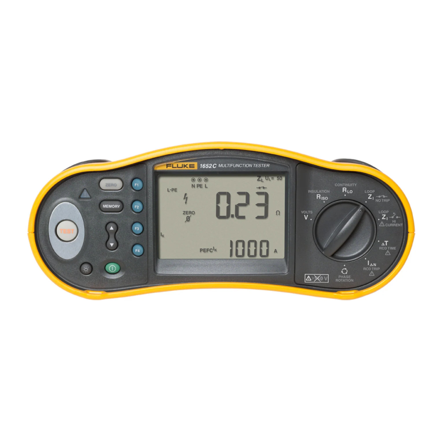
Electrical Installation Tester Operating the Tester Understanding the Display Figures 3 and 4 and Table 6 describe the display features. apx020f.eps Figure 3. Models 1652C and 1653B Display Features... -
Page 18: Display Features
1652C/1653B/1654B Users Manual apx120f.eps Figure 4. Model 1654B Display Features Table 6. Display Features Annunciator Meaning Displays the selected Memory mode. Memory modes are: Select (), Store (), Recall (), or Clear (). Configuration options. Settings you can make ... - Page 19 Electrical Installation Tester Operating the Tester Table 6. Display Features (cont.) Annunciator Meaning Arrows above or below the terminal indicator symbol indicate reversed polarity. Check the connection or check the wiring to correct. Terminal indicator symbol. A terminal ...
- Page 20 1652C/1653B/1654B Users Manual Table 6. Display Features (cont.) Annunciator Meaning = Indicates the preset fault voltage limit. The default setting is 50 V. Some locations require the fault voltage be set to 25 V, as specified by local electrical codes.
- Page 21 See “Error Codes” on page 16 for a listing and explanation of possible error codes. Appears when the instrument is uploading data using Fluke PC software. Name of the secondary measurement function. Test voltage for insulation test.
- Page 22 1652C/1653B/1654B Users Manual Table 6. Display Features (cont.) Annunciator Meaning Secondary display and measurement units. Some tests will return more than one result or return a computed value based on the test result. This will occur with: Volts Secondary display shows line frequency.
-
Page 23: Input Terminals
The Model 1653B and 1654B have an IR (infrared) port, see Figure 23, which allows you to connect the tester to a computer and upload test data using a Fluke PC software product. This automates your troubleshooting or recording process, reduces the possibility of manual error and allows you to collect, organize, and display test data in a format that meets your needs. -
Page 24: Error Codes
Table 7. Error Codes Error Condition Code Solution Self-Test Fails Return the tester to a Fluke Service Center. Over-Temp Wait while the tester cools down. Check the installation, in particular, the voltage Fault Voltage between N and PE. -
Page 25: Power-On Options
Electrical Installation Tester Operating the Tester Power-On Options To select a power-on option, press and the function key simultaneously and then release the button. Power-on options are retained when the tester is turned OFF. See Table 8. Table 8. Power-On Options Keys Power-On Options Loop/Line Impedance I... - Page 26 1652C/1653B/1654B Users Manual Table 8. Power-On Options (cont.) Keys Power-On Options Continuity beeper toggle. Toggles the continuity beeper on and off. The default is on. Extended documentation mode. Simultaneously press the Power button and the Up cursor key. Additional information is stored with ...
-
Page 27: Making Measurements
Electrical Installation Tester Making Measurements Making Measurements Measuring Volts and Frequency apx002f.eps Figure 8. Volts Display/Switch and Terminal Settings To measure voltage and frequency: Turn the rotary switch to the V position. Use all (red, blue, and green) terminals for this test. You can use test leads or mains cord when measuring AC voltage. -
Page 28: Measuring Insulation Resistance
1652C/1653B/1654B Users Manual Measuring Insulation Resistance apx005f.eps Figure 9. Insulation Resistance Display/Switch and Terminal Settings Warning To avoid electric shock, measurements should only be performed on de-energized circuits. To measure insulation resistance: Turn the rotary switch to the R position. -
Page 29: Measuring Continuity
Electrical Installation Tester Making Measurements information before or after the measurement with . The definitions are: P/P = L, P/N = L-N, P/E = L-PE, N/E = N-PE. Measuring Continuity apx003f.eps Figure 10. Continuity Zero Display/Switch and Terminal Settings A continuity test is used to verify the integrity of connections by making a high resolution resistance measurement. -
Page 30: Measuring Loop/Line Impedance
1652C/1653B/1654B Users Manual Note Be sure the batteries are in good charge condition before you zero the test leads. Press and hold until the reading settles. If the continuity beeper is enabled, the tester beeps continuously for measured values less than 2 and there is no stable reading beep for measured values greater than 2 . - Page 31 Electrical Installation Tester Making Measurements Note If the L and N terminals are reversed, the tester will auto-swap them internally and continue testing. If the tester is configured for UK operation, testing will halt. This condition is indicated by arrows above or below the terminal indicator symbol ().
- Page 32 1652C/1653B/1654B Users Manual apx033f.eps Figure 12. Display After Zeroing Press and release . Wait for the test to complete. The primary (upper) display shows the loop impedance. To read the Prospective Earth Fault Current, press the key and select l .
-
Page 33: Earth Resistance Testing By Loop Method
Electrical Installation Tester Making Measurements Warning The symbol on the LCD indicates the high current loop mode - any RCDs in the system will trip - ensure there are no RCDs present. Earth Resistance Testing by Loop Method You can also use the tester to measure the earth resistance component of the total loop resistance. - Page 34 1652C/1653B/1654B Users Manual L-PE loop measurement. This is a way of making a high current, 2-wire loop measurement. It cannot be used on circuits protected by RCDs because it will cause them to trip. Prospective Short Circuit Current (PSC). PSC is the current that can potentially flow if the phase conductor is shorted to the neutral conductor or another phase conductor.
- Page 35 Electrical Installation Tester Making Measurements Warning At this step, be careful not to select L-PE because a high current loop test will take place. Any RCDs in the system will trip if you proceed. Note Connect the leads in a single-phase test to the system live and neutral.
-
Page 36: Measuring Rcd Tripping Time
1652C/1653B/1654B Users Manual Measuring RCD Tripping Time apx008f.eps Figure 16. RCD Tripping Time Display/Switch and Terminal Settings In this test, a calibrated fault current is induced into the circuit, causing the RCD to trip. The meter measures and displays the time required for the RCD to trip. You can perform this test with test leads or using the mains cord. - Page 37 Electrical Installation Tester Making Measurements Potential fields of other earthing installations may influence the measurement. Equipment (motors, capacitors) connected downstream of the RCD may cause considerable extension of the tripping time. Note If the L and N terminals are reversed, the tester will auto-swap them internally and continue testing.
- Page 38 1652C/1653B/1654B Users Manual Press and release . Wait for the test to complete. The primary (upper) display shows the trip time. The secondary (lower) display shows the fault voltage (N to PE) related to the rated residual current. If the trip time is according to the appropriate standard of the RCD, the RCD ...
- Page 39 Electrical Installation Tester Making Measurements Reset the RCD. The tester reverses phases and repeats the 1x test. The RCD should trip and the test results appear in the primary display. Reset the RCD. 10. The tester restores the initial phase setting and supplies 5x the rated RCD current for up to 50 ms.
-
Page 40: Measuring Rcd Tripping Current
1652C/1653B/1654B Users Manual Measuring RCD Tripping Current apx009f.eps Figure 17. RCD Tripping Current/Switch and Terminal Settings This test measures the RCD tripping current by applying a test current and then gradually increasing the current until the RCD trips. You can use the test leads or mains cord for this test. - Page 41 Electrical Installation Tester Making Measurements options, 10, 30, 100, 300, 500 1000 mA, you can use a custom setting with the VAR mode. Press to select the RCD test-current waveform: – AC current to test type AC (standard AC RCD) and type A (pulse-DC sensitive RCD) ...
-
Page 42: Rcd Testing In It Systems
1652C/1653B/1654B Users Manual RCD Testing in IT Systems RCD testing at locations with IT systems requires a special test procedure because the Protective Earth connection is grounded locally and is not tied directly to the power system. The test is conducted at the electrical panel using probes. Use the connection shown in Figure 18 when performing RCD testing on IT electrical systems. - Page 43 Electrical Installation Tester Making Measurements The earth resistance test is a 3-wire test consisting of two test stakes and the earth electrode under test. This test requires an accessory stake kit. Connect as shown in Figure 20. Best accuracy is achieved with the middle stake at 62 % of the distance to the far stake.
-
Page 44: Testing Phase Sequence
1652C/1653B/1654B Users Manual Testing Phase Sequence apx011f.eps Figure 21. Phase Sequence Display/Switch and Terminal Settings Use the connection shown in Figure 22 for a phase sequence test connection. N (L3/Blue) PE (L2/Green) L (L1/Red) apx022f.eps Figure 22. Phase Sequence Test Connection To perform a phase sequence test: Turn the rotary switch to the ... -
Page 45: Memory Mode
Electrical Installation Tester Memory Mode Memory Mode (Model 1653B and 1654B Only You can store measurements on the tester: 1653B – up to 444 1654B – up to 1500 The information stored for each measurement consists of the test function and all user selectable test conditions. -
Page 46: Storing A Measurement
1652C/1653B/1654B Users Manual To enable the data subset number to be changed, press . The data subset number will now be flashing. To enable the data sub number to be changed, press again. The data set number will now be flashing. Press ... -
Page 47: Clearing Memory
Electrical Installation Tester Memory Mode Press to recall the data. The tester display will revert to the Test mode used for the recalled test data, however, the icon still appears, indicating the tester is still in Memory mode. Press ... -
Page 48: Uploading Test Results
The IR data port is disabled when test leads are plugged in. Disconnect test leads before attempting to upload test results. Start the Fluke PC software program. Press to turn on the tester. Refer to the software documentation for complete instructions on how to... -
Page 49: Maintaining The Tester
Electrical Installation Tester Maintaining the Tester Maintaining the Tester Cleaning Periodically wipe the case with a damp cloth and mild detergent. Do not use abrasives or solvents. Dirt or moisture in the terminals can affect readings. To clean the terminals: Turn the meter off and remove all test leads. - Page 50 1652C/1653B/1654B Users Manual To replace the batteries (refer to Figure 24): Press to turn the tester off. Remove the test leads from the terminals. Remove the battery door by using a standard-blade screwdriver to turn the battery door screws (3) one-quarter turn counterclockwise. Press the release latch and slide the battery holder out of the tester.
-
Page 51: Testing The Fuse
Turn the rotary switch to either or switch setting. Short the leads and press and hold . If the fuse is bad, FUSE will appear on the display to indicate the tester is damaged and needs repair. Contact Fluke Service for repair (see Contacting Fluke). -
Page 52: Specifications
1652C/1653B/1654B Users Manual Specifications Features by Model Measurement Function 1652C 1653B 1654B Voltage & Frequency Wiring polarity checker Insulation Resistance Continuity & Resistance Loop & Line Resistance Loop & Line Resistance–m resolution Prospective Earth Fault Current (PEFC/I Prospective Short-Circuit current (PSC/I RCD switching time RCD tripping level ramp test... -
Page 53: General Specifications
Electrical Installation Tester Specifications General Specifications Specification Characteristic Size 10 cm (L) x 25 cm (W) x 12.5 cm (H) Weight (with batteries) 1.3 kg Battery size, quantity Type AA, 6 ea. Battery type Alkaline supplied. Usable with 1.2 V NiCd or NiMH batteries (not supplied) Battery life (typical) 200 hours idling Fuse... -
Page 54: Category Ratings And Usage
1652C/1653B/1654B Users Manual Category Ratings and Usage Printed CAT II CAT III CAT IV Part/Accessory CAT Rating 250 V 500 V 300 V Electrical Installation Tester CAT III 500 V CAT IV 300 V Country-Specific Mains Cord CAT II 250 V Multifunction Probe (red) CAT III 1000 V Test Lead (red/green/blue) -
Page 55: Iso ) (Cont.)
Electrical Installation Tester Specifications Insulation Resistance (R (cont.) 55.02 55.2 55.2 55.2 55.2 66.2 66.2 66.2 66.2 77.2 77.2 77.2 77.2 88.2 88.2 88.2 88.2 99.2 99.2 99.2 99.2 110.2 110.2 110.2 110.2 220.2 220.2 220.2 1035 1000 1150 Continuity (R Maximum Display Maximum Display Limit Value... - Page 56 1652C/1653B/1654B Users Manual Loop Tests (Z Loop Z Loop Z Loop Z Loop R Hi Current No Trip Maximum Maximum Maximum Maximum Limit Limit Limit Limit Display Display Display Display Value Value Value Value Value Value Value Value 0.20 0.14 2.53 2.72 0.30...
-
Page 57: Rcd/Fi Tests ( T, I N)
Electrical Installation Tester Specifications RCD/FI Tests ( T, I N) RCD/FI Time RCD/FI Current Limit Value Maximum Display Value Limit Value Maximum Display Value 18.1 0.43 27.1 0.52 36.1 0.61 45.1 54.1 0.79 63.1 0.88 72.1 1.78 81.1 2.68 90.1 3.58 180.1 4.48... -
Page 58: Earth Tests (R E )
1652C/1653B/1654B Users Manual Earth Tests (R Maximum Display Maximum Display Limit Value Limit Value Value Value 179.8 17.8 268.0 26.8 358.0 35.8 448.0 44.8 538.0 53.8 628.0 62.8 718.0 71.8 808.0 80.8 1000 898.0 89.8 2000 1798.0 AC Voltage Measurement (V) Accuracy Range Resolution... -
Page 59: Insulation Resistance Measurement (R Iso )
Electrical Installation Tester Specifications Insulation Resistance Measurement (R Test Voltages Accuracy of Test Voltage Model 1653B (at rated test Model 1652C Model 1654B current) 250-500-1000 V 50-100-250-500-1000 V +10 %, -0 % Test Insulation Resolution Test Current Accuracy Voltage Resistance Range 50 V 10 k to 50 M 0.01 M... -
Page 60: Loop And Line Impedance (Z I )
1652C/1653B/1654B Users Manual No Trip and Hi Current Modes RCD/FI Mains Input Voltage Range 100 - 500 V ac (50/60 Hz) Input Connection (soft key selection) Loop Impedance: phase to earth Line impedance: phase to neutral Limit on Consecutive Tests Automatic shutdown when internal components are too hot. -
Page 61: Rcd Testing
Electrical Installation Tester Specifications RCD Testing RCD Types Tested RCD Type Model 1652C Model 1653B Model 1654B Notes [1] AC – Responds to ac [2] G – General, no delay [3] S – Time delay [4] A – Responds to pulsed signal [5] B –... -
Page 62: Tripping Speed Test ( T)
1652C/1653B/1654B Users Manual Tripping Speed Test ( T) RCD Current Selection Test Function 10 mA 30 mA 100 mA 300 mA 500 mA 1000 mA x ½, 1 Ramp Auto Notes Mains voltage 100 V – 265 V ac, 50/60 Hz [1] Type B RCDs require mains voltage range of 195 V –... -
Page 63: Rcd/Fi-Tripping Current Measurement/Ramp Test (I N )
Electrical Installation Tester Specifications RCD/FI-Tripping Current Measurement/Ramp Test (I Dwell Time Measurement Current Range Step Size Accuracy Type G Type S 30 % to 110 % of 10 % of I 300 ms/step 500 ms/step RCD rated current Notes [1] 30 % to 150 % for Type A I >10 mA Δ... -
Page 64: Phase Sequence Indication
1652C/1653B/1654B Users Manual Phase Sequence Indication Icon icon Phase Sequence indicator is active. Display of Phase Sequence Displays “1-2-3” in digital display field for correct sequence. Displays “3-2-1” for incorrect phase. Dashes in place of a number indicate a valid determination could not be made. -
Page 65: Operating Ranges And Uncertainties Per En 61557
Electrical Installation Tester Specifications Operating Ranges and Uncertainties per EN 61557 EN 61557 Measurement Function Display Range Nominal Values Range Operating Uncertainty 50 V ac – 500 V ac = 230/400 V ac 0.0 V ac – 500 V ac EN 61557-1 (2% + 2 dgt) f = 50/60 Hz... -
Page 66: Operating Uncertainties Per En 61557
1652C/1653B/1654B Users Manual Operating Uncertainties per EN 61557 The Operating Uncertainty shows the maximum possible uncertainty when all influence factors E1-E10 are counted. Intrinsic 0.80 % 1.50 % 10.00 % 6.00 % 1.00 % 5.00 % 3.50 % Uncertainty A Influence Quantity E1 - Position...
Need help?
Do you have a question about the 1652C and is the answer not in the manual?
Questions and answers