
Subscribe to Our Youtube Channel
Related Manuals for Fluke 1652C


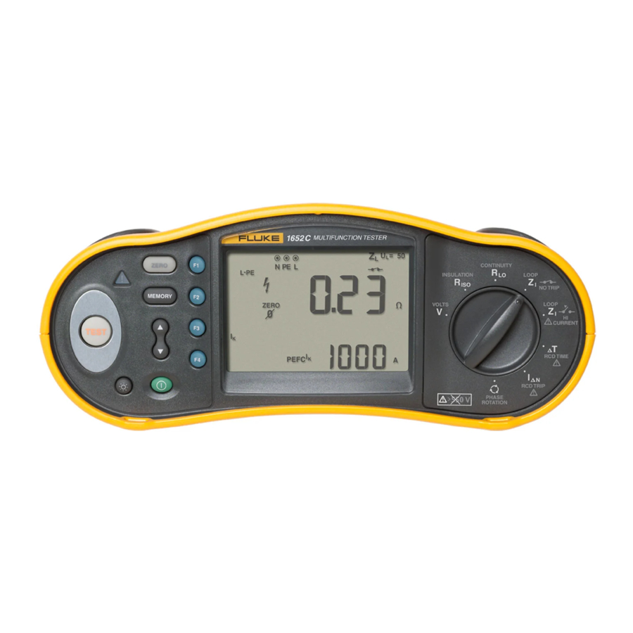
Summary of Contents for Fluke 1652C
- Page 1 ItresE C O N S U L T O R Í A E N E R G É T I C A L A T A M - U S A A N ALI Z A D O R DE I NSTAL ACION ES BT - F LUK E 16 5 3 B Ma nual de C alib ració...
- Page 2 1652C/1653B/1654B Electrical Installation Tester Calibration Manual March 2011 © 2011 Fluke Corporation. All rights reserved. Specifications are subject to change without notice. All product names are trademarks of their respective companies.
- Page 3 LIMITED WARRANTY AND LIMITATION OF LIABILITY Each Fluke product is warranted to be free from defects in material and workmanship under normal use and service. The warranty period is three years and begins on the date of shipment. Parts, product repairs, and services are warranted for 90 days.
-
Page 4: Table Of Contents
Table of Contents Title Page Introduction......................1 How to Contact Fluke ..................1 Precautions and Safety Information..............2 Specifications..................... 4 General Specifications................... 4 Category Ratings and Usage................5 Electrical Measurement Specifications ............5 Insulation Resistance (R ) ..............5 Continuity (R ) .................. - Page 5 1652C/1653B/1654B Calibration Manual Input Jack Sensing Test ................. 19 IR Port Verification ..................19 Touch Pad Sense Test..................20 Memory Mode Test (1653B and 1654B Only) ..........21 Accuracy Tests....................22 Volt and Insulation Functions ............... 22 Continuity Function..................24 LOOP Z NO TRIP, L-PE................
- Page 6 List of Tables Table Title Page Symbols........................2 Equipment Requirements ..................15 Volt and Insulation Accuracy Tests ............... 23 Continuity Accuracy Tests ..................25 LOOP Z NO TRIP Accuracy Tests ............... 26 Loop Z Hi Current Accuracy Tests ............... 28 RCD Trip Current Accuracy Tests.................
- Page 7 1652C/1653B/1654B Calibration Manual...
- Page 8 List of Figures Figure Title Page Battery Replacement ....................17 1652C and 1653B LCD Tests ................18 1654B LCD Tests....................19 Touch Pad Sense Test .................... 21 Volts and Insulation Accuracy Tests..............22 Continuity Tests (4-Wire Connection)..............24 LOOP Z NO TRIP Test..................
- Page 9 1652C/1653B/1654B Calibration Manual...
-
Page 10: Introduction
• Accuracy Tests • Accessories and Replaceable Parts • For complete instructions on how to use the Tester, refer to the 1652C/1653B/1654B Users Manual. How to Contact Fluke To contact Fluke, call one of the telephone numbers that follow: •... -
Page 11: Precautions And Safety Information
Do not dispose of this product as unsorted municipal waste. Go to Battery or battery compartment. Low Fluke’s website for recycling battery when shown on display information. CAT III equipment is designed to protect against transients in equipment in fixed-... - Page 12 Electrical Installation Tester Precautions and Safety Information Safety Information To prevent possible electrical shock, fire, or personal injury: • Use the product only as specified, or the protection supplied by the product can be compromised. • Do not use the product around explosive gas, vapor or in damp or wet environments.
-
Page 13: Specifications
1652C/1653B/1654B Calibration Manual Specifications General Specifications Specification Characteristic Size 10 cm (L) x 25 cm (W) x 12.5 cm (H) Weight (with batteries) 1.3 kg Battery size, quantity Type AA, 6 ea. Battery type Alkaline supplied. Usable with 1.2 V NiCd or NiMH batteries (not supplied) -
Page 14: Category Ratings And Usage
Electrical Installation Tester Specifications Category Ratings and Usage Printed CAT II CAT III CAT IV Part/Accessory CAT Rating 250 V 500 V 300 V 165XB Electrical Installation Tester CAT III 500 V √ √ √ CAT IV 300 V √ √... -
Page 15: Loop Tests
1652C/1653B/1654B Calibration Manual Continuity (R Maximum Display Maximum Display Limit Value Limit Value Value Value 0.16 2.68 0.25 3.58 0.34 4.48 0.43 5.38 0.52 6.28 0.61 7.18 8.08 0.79 8.98 0.88 17.98 1.78 26.8 Loop Tests (Z Loop Z Loop Z... -
Page 16: Rcd/Fi Tests ( T, I N)
Electrical Installation Tester Specifications RCD/FI Tests ( T, I ∆ ∆ RCD/FI Time RCD/FI Current Limit Value Maximum Display Value Limit Value Maximum Display Value 18.1 0.43 27.1 0.52 36.1 0.61 45.1 54.1 0.79 63.1 0.88 72.1 1.78 81.1 2.68 90.1 3.58 180.1... -
Page 17: Earth Tests (R )
1652C/1653B/1654B Calibration Manual Earth Tests (R Maximum Display Maximum Display Limit Value Limit Value Value Value 179.8 17.8 268.0 26.8 358.0 35.8 448.0 44.8 538.0 53.8 628.0 62.8 718.0 71.8 808.0 80.8 1000 898.0 89.8 2000 1798.0 AC Voltage Measurement (V) -
Page 18: Insulation Resistance Measurement (R Iso )
Electrical Installation Tester Specifications Insulation Resistance Measurement (R Test Voltages Accuracy of Test Voltage Model 1653B (at rated test Model 1652C Model 1654B current) 250-500-1000 V 50-100-250-500-1000 V +10 %, -0 % Test Insulation Resolution Test Current Accuracy Voltage Resistance Range 50 V 10 kΩ... -
Page 19: Prospective Earth Fault Current Test (Psc/I )
Resolution Units <1000 A >1000 A 0.1 kA Accuracy Determined by accuracy of loop resistance and mains voltage measurements. RCD Testing RCD Types Tested RCD Type Model 1652C Model 1653B Model 1654B √ √ √ √ √ √ √ √... -
Page 20: Tripping Speed Test ( ∆ T)
Electrical Installation Tester Specifications Tripping Speed Test ( ∆ RCD Current Selection Test Function 10 mA 30 mA 100 mA 300 mA 500 mA 1000 mA x ½, 1 √ √ √ √ √ √ √ √ √ √ Ramp √... -
Page 21: Earth Resistance Test (R E )
1652C/1653B/1654B Calibration Manual Earth Resistance Test (R Models 1653B and 1654B Only. This product is intended to be used to measure installations in process plants, industrial installations, and residential applications. Range Resolution Accuracy 200 Ω 0.1 Ω ±(2 % + 5 digits) 2000 Ω... -
Page 22: Operating Ranges And Uncertainties Per En 61557
Electrical Installation Tester Specifications Operating Ranges and Uncertainties per EN 61557 EN 61557 Measurement Function Display Range Nominal Values Range Operating Uncertainty 50 V ac – 500 V ac = 230/400 V ac 0.0 V ac – 500 V ac EN 61557-1 ±(2% + 2 dgt) f = 50/60 Hz... -
Page 23: Operating Uncertainties Per En 61557
1652C/1653B/1654B Calibration Manual Operating Uncertainties per EN 61557 The Operating Uncertainty shows the maximum possible uncertainty when all influence factors E1-E10 are counted. Intrinsic 0.80 % 1.50 % 10.00 % 6.00 % 1.00 % 5.00 % 3.50 % Uncertainty A... -
Page 24: Equipment Requirements
Recommended Equipment Description Model AC Voltage Range: 0 to 500 V ac Multifunction Electrical Tester Fluke 5320A Calibrator Accuracy: ±0.215 % Calibrator Frequency Range: 50 Hz Insulation Resistance: 10 kΩ to 900 MΩ Accuracy: 10 kΩ to 200 MΩ = ±0.413 % 200 MΩ... -
Page 25: Basic Maintenance
1652C/1653B/1654B Calibration Manual Basic Maintenance This section contains information about the basic maintenance of the Tester. Warning To prevent possible electrical shock, fire, or personal injury: • Remove the input signals before you clean the product. • Remove all probes, test leads, and accessories before the case is opened. -
Page 26: How To Test And Replace The Fuse
1. Turn the rotary switch to either 2. Short the leads. 3. Press and hold If the fuse is bad, FUSE will appear on the display to indicate the Tester is damaged and needs repair. Contact Fluke Service for repair (see How to Contact Fluke). -
Page 27: Performance Tests
, power the Tester back on. 3. Continue to hold down after releasing 4. Compare the display segments to Figure 2 for the 1652C and 1653B. Compare the display segments to Figure 3 for the 1654B. Check for any missing segments or poor contrast areas. -
Page 28: Input Jack Sensing Test
Electrical Installation Tester Performance Tests gad010.eps Figure 3. 1654B LCD Tests Input Jack Sensing Test This test determines if the input jack detect-circuits are operating correctly: 1. Install test leads into the L and PE UUT input jacks. 2. Set the rotary switch for Loop Z and use to select L-PE. -
Page 29: Touch Pad Sense Test
1652C/1653B/1654B Calibration Manual 7. The Tester should return the response: FLUKE 165XB, VX.XX/X.XX, XXXXXXX (indicates the model, software version, and unit serial number) Note If the PC indicates that the Tester is not connected, ensure that the COM port is correct and that the IR Serial Cable is properly connected and aligned to the UUT IR window. -
Page 30: Memory Mode Test (1653B And 1654B Only)
Electrical Installation Tester Performance Tests Fluke 5320A 5320A MU LTIFUNCTION ELECTRICAL OUTPUT , HI , mA LO - SENSE 50V PK 1500V PK 20V PK 20V PK GND , 280V 280V 20V PK METER INPUT METER (L2/Green) C AT I... -
Page 31: Accuracy Tests
1652C/1653B/1654B Calibration Manual Accuracy Tests Volt and Insulation Functions To verify the accuracy of the UUT volt and insulation functions: 1. Turn the UUT rotary switch to VOLTS V position. 2. Press until L-PE appears in the upper left corner of the display. - Page 32 Electrical Installation Tester Accuracy Tests Table 3. Volt and Insulation Accuracy Tests UUT Display Reading Frequency Step Function Range Input Level Lower Upper or Model Limit Limit Volts, AC 500 V 25 V 50 Hz 24.5 25.5 250 V 50 Hz 247.7 252.3 475 V...
-
Page 33: Continuity Function
1652C/1653B/1654B Calibration Manual Continuity Function To verify accuracy of the UUT continuity function: 1. Turn the UUT rotary switch to CONTINUITY R 2. Connect a shorting bar directly to the UUT PE and L input jacks. 3. Press and hold the UUT until the Tester displays a reading and the ZERO ∅... -
Page 34: Loop Z Ino Trip, L-Pe
5. Read the UUT display. The display should read from 0.00 to 0.06 Ω. 6. Disconnect the shorting bar and connect test leads to the UUT L-PE-N input jacks. 7. Short the far end of the test leads together with a Zero Adapter (Fluke P/N 3301338) See Figure 8. - Page 35 1652C/1653B/1654B Calibration Manual Complete the steps in Table 5 as follows: 1. Connect the test leads to the UUT, Decade R Box, and 5320A, as shown in Figure 7. 2. Set the Decade R value for 18 Ω. 3. Set the UUT rotary switch to LOOP Z NO TRIP function.
-
Page 36: Loop Z Hi Current
Electrical Installation Tester Accuracy Tests Fluke 5320A 5320A MULTIFUNCTION ELECTRICAL TESTER CALIBR OUTPUT , HI , mA - SENSE 50V PK 1500V PK 20V PK 20V PK GND , 280V 280V 20V PK METER INPUT METER CAT I 1000V CAT II... - Page 37 Calibration Manual 5. Disconnect the shorting bar and connect test leads to the UUT L-PE-N input jacks. 6. Short the far end of the test leads together with a Zero Adapter (Fluke P/N 3301338) See Figure 8. 7. Press and hold for approximately three seconds until the UUT ZERO ∅...
-
Page 38: Ircd Trip Current
Electrical Installation Tester Accuracy Tests Fluke Zero Adapter (L3/Blue) (L2/Green) (L1/Red) gad008.eps Figure 8. Loop Zero Tests RCD Trip Current Warning To prevent possible electrical shock, fire, or personal injury, do not touch the L or N input jacks while performing the following tests. - Page 39 1652C/1653B/1654B Calibration Manual Table 7. RCD Trip Current Accuracy Tests UUT Settings Current Accuracy Step Spec Function Lo Limit Hi Limit 10 mA x1/2 0° -10 % + 0 4.50 5.00 10 mA x1/2 0° -10 % + 0 3.15 3.50...
-
Page 40: Rcd Trip Time
Electrical Installation Tester Accuracy Tests RCD Trip Time Warning To prevent possible electrical shock, fire, or personal injury, do not touch the L or N input jacks while performing the following tests. These input jacks have line voltage on them during the test. -
Page 41: Earth Resistance (1653B And 1654B Only)
1652C/1653B/1654B Calibration Manual Earth Resistance (1653B and 1654B Only) To verify the UUT accuracy for measuring earth resistance, complete the following tests: 1. Turn the UUT to the R Earth function. 2. Connect the UUT to the 5320A LO Ω Output terminals as shown in Figure 10. -
Page 42: Accessories And Replaceable Parts
Accessories and Replaceable Parts Accessories and Replaceable Parts Accessories and user-replaceable parts are listed in Table 10 and shown in Figure 11. See How to Contact Fluke to order parts. Warning For safe operation and maintenance of the product, use only specified replacement parts. - Page 43 1652C/1653B/1654B Calibration Manual MP12 BT1-BT6 MP41 MP11 MP49 MP30 MP26 MP31 gad009.eps Figure 11. Accessories and Replaceable Parts...
Need help?
Do you have a question about the 1652C and is the answer not in the manual?
Questions and answers