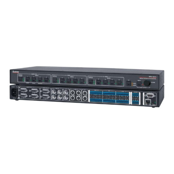
Extron electronics MPX 423 A User Manual
Media presentation matrix switcher
Hide thumbs
Also See for MPX 423 A:
- User manual (64 pages) ,
- Quick manual (4 pages) ,
- User manual (56 pages)

Related Manuals for Extron electronics MPX 423 A


Summary of Contents for Extron electronics MPX 423 A
- Page 1 User Guide Matrix Switchers MPX 423 A Media Presentation Matrix Switcher 68-972-01 Rev. C 02 20...
- Page 2 Safety Instructions Safety Instructions • English Istruzioni di sicurezza • Italiano AVVERTENZA: Il simbolo, , se usato sul prodotto, serve ad WARNING: This symbol, ,when used on the product, is avvertire l’utente della presenza di tensione non isolata pericolosa intended to alert the user of the presence of uninsulated dangerous all’interno del contenitore del prodotto che può...
- Page 3 , and trademarks are the property of RGB Systems, Inc. or (®) (SM) (™) Extron Electronics (see the current list of trademarks on the Terms of Use page at www.extron.com): Registered Trademarks (®) Extron, Cable Cubby, ControlScript, CrossPoint, DTP, eBUS, EDID Manager, EDID Minder, Flat Field, FlexOS, Glitch Free, Global Configurator, Global Scripter, GlobalViewer, Hideaway, HyperLane, IP Intercom, IP Link, Key Minder, LinkLicense, LockIt, MediaLink, MediaPort, NetPA,...
- Page 4 FCC Class A Notice This equipment has been tested and found to comply with the limits for a Class A digital device, pursuant to part 15 of the FCC rules. The Class A limits provide reasonable protection against harmful interference when the equipment is operated in a commercial environment.
- Page 5 Conventions Used in this Guide Notifications The following notifications are used in this guide: CAUTION: Risk of minor personal injury. ATTENTION : Risque de blessure mineure. ATTENTION: Risk of property damage. • • Risque de dommages matériels. NOTE: A note draws attention to important information. TIP: A tip provides a suggestion to make working with the application easier.
-
Page 7: Table Of Contents
Volume Control (Output 1 Only) ..... 13 Audio Mute (Output 1 Only) ......13 Adjusting the Input Audio Level ..... 14 Audio Outputs ..........14 Resetting the Unit ..........15 Hardware Reset Modes ........ 15 Factory Reset Modes........15 MPX 423 A • Contents... - Page 8 MPX 423 A • Contents viii...
-
Page 9: Introduction
Four composite video (NTSC, PAL, or SECAM) inputs on BNC female connectors. • • Multiple video outputs — Two outputs per video format for simultaneous (in separate switcher mode), or one at a time (in single switcher mode) display on VGA, composite video, or S-video devices. MPX 423 A • Introduction... - Page 10 Versatile mounting options — The MPX 423 A is housed in a rugged, 1U high, full rack wide metal enclosure, and can be easily mounted into any rack or podium, or under a desk. • Internal international power supply — The internal power supply provides worldwide power compatibility. MPX 423 A • Introduction...
-
Page 11: Installation
(composite), or S-video groups (up to four audio sources for each group). For audio output, connect up to two audio output devices. If the MPX 423 A matrix switcher is to be connected to a computer or host controller for remote control, see RS-232 and Ethernet Control on page 7 and do one of the... -
Page 12: Rack Mounting The Switcher
Insert the four wood screws into the pilot holes. Fasten each screw into the installation surface until just less than 1/4" (6.4 mm) of the screw head protrudes. MPX 423 A • Installation... -
Page 13: Rear Panel Connectors
Tweeker, pointed stylus or ballpoint pen. The unit can be reset to five modes (see Resetting the Unit on page 15). Reset LED — The green LED blinks to show reset mode indications and to show that § power is on (see Resetting the Unit on page 15). MPX 423 A • Installation... -
Page 14: Connecting The Matrix Switcher
Power up the input and output devices, then connect power to the rear AC connector of the switcher. NOTE: The boot-up message reads: © Copyright 2007, Extron Electronics, MPX 423 A, V1.02, 60-683-01 (for RS-232 connection). Extron... -
Page 15: Rs-232 And Ethernet Control
Insert Twisted TIA/EIA-T568B T568B Pair Wires Figure 4. RJ-45 Connector For more detailed information, see Remote Control Port (RS-232) on page 16. MPX 423 A • Installation... -
Page 16: Operation
Provides a method of accessing the front panel security lockout function. • Acts as a system reset button. • Functions with the Mute button to set an RGB delay. • MPX 423 A • Operation... -
Page 17: Switcher Modes And Operation
The audio operates independently as a 12 inputs to 2 outputs matrix switcher. NOTE: Both audio outputs can be configured in Separate mode. That is, the unit emulates three 2-output switchers with 4 inputs each. MPX 423 A • Operation... -
Page 18: Establishing A Tie
Press and hold the Mode button for approximately 3 seconds. The Single and Separate LEDs light. One is lit solidly, one is blinking. The blinking LED indicates the currently active switching mode (Single or Separate). COMPUTER OUTPUTS/ INPUTS AUDIO MODE SINGLE SEPARATE Mode button MPX 423 A • Operation... -
Page 19: Muting And Unmuting Video, Audio, Or Both
The muted output LED blinks. • Selecting video and audio (I/O button) to view muted outputs is not recommended. Blinking output LEDs could also indicate an audio or follow-all tie. MPX 423 A • Operation... -
Page 20: Locking And Unlocking The Front Panel
The source at input 9 provides the genlock sync signal to all of the S-Video group inputs. This happens automatically when inputs are connected to inputs 5 and 9. No configuration is required. MPX 423 A • Operation... -
Page 21: Audio
LED lights when audio is muted. If a muted output is not at maximum attenuation, it is disconnected. Press the audio Mute button again to unmute the output and return to the previous output level. NOTE: Control of audio output 2 is available through RS-232 or Ethernet and Telnet only. MPX 423 A • Operation... -
Page 22: Adjusting The Input Audio Level
Connect the sleeve to ground (Gnd, ). Connecting the sleeve to a negative (–) • terminal damages the audio output circuits. Connectez le manchon à la borne de terre (Gnd, ). Connecter le manchon à une • borne négative (–) endommagera les circuits de la sortie audio. MPX 423 A • Operation... -
Page 23: Resetting The Unit
Press and hold the I/O button on the front panel while plugging in AC power. Continue to hold the I/O button until all LEDs on the front panel blink. Once the I/O button is released, power-up continues, and the LEDs return to their default configuration. MPX 423 A • Operation... -
Page 24: Sis Programming And Control
No response is required from the host. The unit-initiated message is listed here. (c) Copyright 2007, Extron Electronics, MPX 423 A, Vx.xx , 60-683-01 Day, DD Mon YYYY HH:MM:SS Vx.xx is the firmware version number. -
Page 25: Password Information
The following copyright message is initiated by the MPX 423 A matrix switcher at power-up (for an RS-232 connection): © Copyright 2007, Extron Electronics, MPX 423 A, Vx.xx, 60-683-01 NOTE: Vx.xx = the firmware version number. MPX 423 A • SIS Programming and Control... -
Page 26: Commands And Responses
NOTE: If you make adjustments (changes to volume, and so forth), via the front panel, RS-232 or IP, it takes 100 seconds for the new data to be saved to flash memory. MPX 423 A • SIS Programming and Control... -
Page 27: Symbol Definitions
Flow control: Hardware, Software, None characters coming into a serial port before Data pacing (specified in milliseconds terminating (default = 2 = 20 ms, between bytes): 0000 - 1000 (default = max.= 32767) 0 ms) MPX 423 A • SIS Programming and Control... -
Page 28: Command And Response Table For Sis Commands
Volume adjustment range (0%-100%) [min. = 0 through max. = 64, default = (0 dB)] in 1 dB steps except from 1 to 0 = -30 dB Tie an Input to All Outputs (Audio Only) Tie an input to all outputs •Aud Tie audio input to all audio (audio only) outputs. MPX 423 A • SIS Programming and Control... - Page 29 Switcher mode selection X1!] Set output to switcher mode View switcher mode X1!] Read the mode of switcher output = Switcher mode selection: 1 = Single mode; 2 = Separate mode (default). KEY: MPX 423 A • SIS Programming and Control...
- Page 30 1, 2 = VGA & audio, and mode selection outputs. 3, 4 = Composite video. 5, 6 = S-video On/off status: 0 = off/disable, 1 = on/enable. NOTE: These commands are not case sensitive. Z and z can be used interchangeably. MPX 423 A • SIS Programming and Control...
- Page 31 Lock all front panel functions Enable lock mode 1. Exe 1 Unlock all front panel Unlock front panel. Exe 0 functions View lock status On/off status: 0 = off/disable; 1 = on/enable KEY: MPX 423 A • SIS Programming and Control...
- Page 32 Read GMT offset X3(] KEY: X3& GMT date and time (short version): (MM/DDD/YY•HH:MM:SS) GMT date and time (long version): [WWW,•DD•MMM•YYYY• HH:MM:SS•GMT] GMT offset (-12.0 through 14.0 hours and minutes removed from GMT) MPX 423 A • SIS Programming and Control...
- Page 33 Read subnet mask X2&] Set gateway IP EX2& X2&] Read gateway IP X2&] KEY: X2& IP address or subnet mask (###.###.###.###) Hardware (MAC) address (##-##-##-##-##-##) DHCP (0 = off; 1 = on) MPX 423 A • SIS Programming and Control...
- Page 34 Verbose status: 0 = none (default for Telnet connection) 1 = Verbose mode (default for RS-232/RS-422 connection) 2 = Tagged response for queries 3 = Verbose mode & tagged response for queries MPX 423 A • SIS Programming and Control...
-
Page 35: Ethernet Control
Click in the Password field and enter the appropriate administrator or user password. NOTE: The factory configured passwords for this device have been set to the device serial number. Passwords are case sensitive. Performing a mode 5 absolute system reset sets the passwords to no password. MPX 423 A • Ethernet Control... -
Page 36: Navigating The Default Web Pages
The System Status page, shown below, is the default page of the on-board web server, and provides an overview of the status of various aspects of the matrix switcher. It provides immediate system information, power status, and serial port settings for the MPX. Figure 8. System Status Page MPX 423 A • Ethernet Control... - Page 37 The DSVP page, accessible from the Status tab, allows you to view a snapshot-in-time of the input frequencies of connected inputs on the Digital Sync Validation Processing (DSVP) page (see figure 9). Figure 9. DSVP Page MPX 423 A • Ethernet Control...
-
Page 38: Configuration Tab
{space} ~ @ = ‘ [ ] { } < > ’ “ ; : | \ ? The default unit name is a combination of the product name followed by the last three octet pairs from the MAC address. MPX 423 A • Ethernet Control... - Page 39 Date/Time Settings The Date/Time Settings fields provide a location for viewing and setting the date and time functions. Click Local Date/Time to synchronize the MPX internal clock with the time setting of the PC. MPX 423 A • Ethernet Control...
-
Page 40: Passwords Page
Also, an administrator password must be created before a user password can be created. To clear an existing password so that no password is required: Delete the asterisks in the Password field and place a blank space in the field. Click the Submit button. MPX 423 A • Ethernet Control... -
Page 41: Firmware Upgrade Page
The file can be downloaded from the same page as firmware.. Submit required information and follow on-screen instructions to start the download. Note where the file is saved. From the save location, open the executable (.exe) file. MPX 423 A • Ethernet Control... - Page 42 Click the Open button. The dialog box closes and the selected file is listed on the Firmware Upgrade page. Click the Upload button. The firmware upload to the MPX 423 A switcher begins. The process can take several minutes to complete, and the unit may reboot. MPX 423 A • Ethernet Control...
-
Page 43: File Management Page
Delete button of the next file. To delete all files, click the Delete All button. The file count reverts to 0 and all pages are deleted. MPX 423 A • Ethernet Control... -
Page 44: Control Tab
Click on an input or output selection button to create a tie (if not tied) or untie (if tied) of the input and output associated with that button. The button color represents the signal type for the tie: green for video, red for audio and amber for audio and video. MPX 423 A • Ethernet Control... -
Page 45: Video & Audio Settings Page
NOTE: If you choose an output number greater than 2, (that is, outputs 3 or 4 for video signals and 5 or 6 for S-video signals) the audio mute options are no longer accessible. MPX 423 A • Ethernet Control... - Page 46 Click on the Volume Steps (64 max) drop-down list ( and select the desired output level ( to 64) (see the table on the next page to compare the value in this list to attenuation and output volume). MPX 423 A • Ethernet Control...
-
Page 47: Special Characters
The switcher rejects the following characters: {space} ~ @ = ‘ [ ] { } < > ’ “ semicolon (;) colon (:) | \ and ? MPX 423 A • Ethernet Control... - Page 48 Extron Electronics makes no further warranties either expressed or implied with respect to the product and its quality, performance, merchantability, or fitness for any particular use. In no event will Extron Electronics be liable for direct, indirect, or consequential damages resulting from any defect in this product even if Extron Electronics has been advised of such damage.
Need help?
Do you have a question about the MPX 423 A and is the answer not in the manual?
Questions and answers