
Related Manuals for MTD 31AH6ZFH729


Summary of Contents for MTD 31AH6ZFH729
- Page 1 Safe Operation Practices • Set-Up • Operation • Maintenance • Service • Troubleshooting • Warranty iOi _, 600-Series Snow Thrower m E/F Style MTD LLC, P.O. BOX 361131 CLEVELAND, OHiO 44136-0019 PrintedIn USA FormNo.769-04098 (August6, 2008)
- Page 2 Choose from the options below: Visit us on the web at www.mtdproducts.com Call a Customer Support Representative at (800) 800-7310 or (330) 220-4683 Write us at MTD LLC • EO. Box 361131 • Cleveland, OH • 44136-0019...
- Page 3 ImportantSafeOperation Practices WARNING! This symbol points out important safety instructions which, if not followed, could endanger the personal safety and/or property of yourself and others. Read and follow all instructions in this manual before attempting to operate this machine. Failure to comply with these instructions may result in personal injury.
- Page 4 Never run an engine indoors or in a poorly ventilated area. SafeHandling of Gasoline Engine exhaust contains carbon monoxide, an odorless To avoid personal injury or property damage use extreme care and deadly gas. in handling gasoline. Gasoline is extremely flammable and the Do not operate...
- Page 5 According to the Consumer Products Safety Commission Clearinga CloggedDischarge Chute (CPSC) and the U.S. Environmental Protection Agency (EPA), Hand contact with the rotating impeller inside the discharge this product has an Average Useful Life of seven (7) years, chute is the most common cause of injury associated with snow or 60 hours of operation.
- Page 6 Safety Symbols This page depicts and describes safety symbols that may appear on this product. Read, understand, and follow all instructions on the machine before attempting to assemble and operate. READ THE OPERATOR'S MANUAL(S) Read, understand, and follow all instructions in the manual(s) before attempting assemble and operate...
- Page 7 Assembly & Set-Up Contentsof Carton One Snow Thrower One Chute Directional Control Two Replacement Auger Shear Pins One Snow Thrower Operator's One Briggs & Stratton Engine One Chute Assembly Manual Operator's Manual Assembly Handle Place the shift lever in the Forward-6 position Observe the lower rear area of the snow thrower to be sure...
- Page 8 Finish securing chute control assembly to chute support Remove the hairpin clip from the rear of the chute control bracket with wing nut and hex screw removed earlier. assembly. See Fig. 3-4. Secure the chute directional control rod to the chute control assembly with the hairpin...
- Page 9 ChuteClean-OutTool Adjustments The chute clean-out tool is fastened to the top of the auger Skid Shoes housing with a mounting clip and a cable tie at the factory. the cable tie before operating the snow thrower. See Fig. 3-8. The snow thrower skid shoes are adjusted upward at the factory for shipping...
- Page 10 Auger Control carefully read and follow all instructions below. WARNING! Prior to operating your snow thrower, Perform all adjustments to verify your snow thrower is operating safely and properly. Check the adjustment of the auger control as follows: When the auger control is released and in the disengaged "up"...
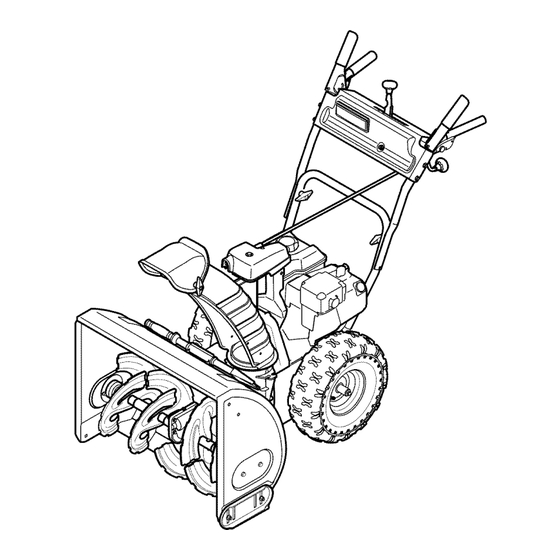
- Page 11 Controls a nd Features Drive Control Shift Lever Auger Control Gas Cap Chute Assembly Chute Directional Control Primer il Fill Choke Control Ignition Stop Recoil Starter Handle Electric Start Augers Button Electric Starter Outlet Skid Shoe Figure 4=1 Snow thrower controls and features are described...
- Page 12 Stop Switch AugerControl The stop switch is located on the rear of the engine. It will shut AUGER off the engine when moved into the STOP position. CONTROL Primer Pressing the primer forces fuel directly into the engine's carburetor to aid in cold-weather starting.
- Page 13 Chute Directional Control Chute Clean-Out Tool CHUTE DIRECTIONAL CONTROL clogged chute assembly. Shut off engine and remain ARNING! Never use your hands to clear a behind handles until all moving parts have stopped before unclogging. DISCHARGE DISCHARGE LEFT The chute clean-out tool is conveniently fastened to the rear of...
- Page 14 Operation When disconnecting the extension cord, always unplug Starting TheEngine end at the three-prong wall outlet before unplugging Make certain both the auger control and drive control opposite end from the snow thrower. in the disengaged (released) position. RecoilStarter Insert ignition key into slot.
- Page 15 ToEngageDrive With the throttle control in the Fast (rabbit) position, move shift lever into one of the six forward (F) positions or two reverse (R) positions. Select a speed appropriate for the snow conditions and a pace you're comfortable with. Squeeze the drive control against the handle the snow...
- Page 16 Maintenance& Adjustments Maintenance Lubrication GearShaft Engine Refer to the Briggs & Stratton Engine manual packed with your The gear (hex) shaft should be lubricated at least once a season machine for all engine maintenance. or after every twenty-five (25) hours of operation. ShavePlateand Skid Shoes Carefully pivot the snow thrower...
- Page 17 Auger Shaft Adjustments At least once a season, remove the shear pins from the auger Shift Cable shaft. Spray lubricant inside the shaft and around the spacers and the flange bearings found at either end of the shaft. If the full range of speeds (forward and reverse) cannot be See Fig.
- Page 18 DriveControl ChuteAssembly When the drive control is released and in the disengaged "up" If the chute directional control is difficult to crank, or if the chute position, the cable should have very little slack. It should NOT be assembly is rotating as a result of vibration, the preload on the...
- Page 19 Service Carefully pivot the snow thrower up and forward so that it Belt Replacement rests on the auger housing. Auger Belt Remove the frame cover from the underside of the snow thrower by removing four self-tapping screws which secure To remove and replace your snow thrower's auger belt, proceed it.
- Page 20 DriveBelt Remove the belt from around the auger pulley, and slip the belt between the support bracket and the auger pulley. To remove and replace your snow thrower's drive belt, proceed See Fig. 7-5. as follows: Allow the engine to run until it is out of fuel. Remove the plastic belt cover on the front of the engine by removing the two self-tapping...
- Page 21 Friction WheelRemoval Slip the drive belt offthe pulley and between friction wheel and friction wheel disc. See Fig. 7-7. If the snow thrower fails to drive with the drive control engaged, and performing the drive control cable adjustment fails to correct the problem, the friction...
- Page 22 Follow the previous steps in reverse order to reassemble Carefully remove the hex nut which secures the hex shaft components. If you're disassembling the friction wheel and to the snow thrower frame and lightly tap the shaft's end to replacing only the rubber ring, proceed as follows: dislodge the ball bearing from the right side of the frame.
- Page 23 Troubleshooting Problem Cause Remedy Engine runs erratic 1. Engine running on CHOKE. 1. Move choke lever to OFF position. 2. Blocked fuel line or stale fuel. 2. Fill tank with clean, fresh gasoline. 3. Drain fuel tank. Refill with fresh fuel. 3.
- Page 24 Replacement P arts Component Part Number and Description q>+ 929-0071 Extention Cord, 110V 954-04050 Auger Drive Belt 754-0367 Wheel Drive Belt 684-04153 Friction Wheel Assembly 935-04054 Friction Wheel Rubber 925-1658 Halogen Lamp, 12V, 27W 738-04124A Shear Pin, 1.50 714-04040 Bow-tie Cotter Pin 784-5580 Slide Shoe, Standard (Steel) 731-06439...
- Page 26 SECTION NOTES...
- Page 27 SECTION 11 -- NOTES...
- Page 28 MANUFACTURER'S LiMiTED WARRANTY The limited warranty set forth below is given by MTD LLC with c. Routine maintenance items such as lubricants, filters, blade respect to new merchandise purchased and used in the United States sharpening, tune-ups, brake adjustments, clutch adjustments,...
Need help?
Do you have a question about the 31AH6ZFH729 and is the answer not in the manual?
Questions and answers