MTD 600-Series L Style Operator's Manual
Snow thrower l-style
Hide thumbs
Also See for 600-Series L Style:
- Operator's manual (25 pages) ,
- Operator's manual (29 pages) ,
- Operator's manual (28 pages)

Related Manuals for MTD 600-Series L Style


Summary of Contents for MTD 600-Series L Style
- Page 1 Safe Operation Practices • Set-Up • Operation • Maintenance • Service • Troubleshooting • Warranty 600-Series Snow Thrower m L Style MTD LLC, P.O. BOX 361131 CLEVELAND, OHiO 44136-0019 PrintedIn USA FormNo.769-04035 (June5, 2008)
-
Page 2: Customer Support
Choose from the options below: Visit us on the web at www.mtdproducts.com Call a Customer Support Representative at (800) 800-7310 or (330) 220-4683 Write us at MTD LLC • EO. Box 361131 • Cleveland, OH • 44136-0019... -
Page 3: Important Safe Operation Practices
ImportantSafeOperation Practices WARNING! This symbol points out important safety instructions which, if not followed, could endanger the personal safety and/or property of yourself and others. Read and follow all instructions in this manual before attempting to operate this machine. Failure to comply with these instructions may result in personal injury. -
Page 4: Safe Handling Of Gasoline
Never run an engine indoors or in a poorly ventilated area. SafeHandling of Gasoline Engine exhaust contains carbon monoxide, an odorless To avoid personal injury or property damage use extreme care and deadly gas. in handling gasoline. Gasoline is extremely flammable and the Do not operate... -
Page 5: Maintenance And Storage
Maintenance & Storage Donot modify engine Never tamper with safety devices. Check their proper To avoid serious injury or death, do not modify engine in any operation regularly. Refer to the maintenance way. Tampering with the governor setting can lead to a runaway adjustment sections of this manual. -
Page 6: Safety Symbols
Safety Symbols This page depicts and describes safety symbols that may appear on this product. Read, understand, and follow all instructions on the machine before attempting to assemble and operate. READ THE OPERATOR'S MANUAL(S) Read, understand, and follow all instructions in the manual(s) before attempting assemble and operate... -
Page 7: Assembly And Setup
Assembly & Set-Up Contentsof Carton One Snow Thrower Two Replacement Auger Shear Pins One Product Registration Card One Snow Thrower Operator's Manual Assembly Handle Place the shift lever in the Forward-6 position Observe the lower rear area of the snow thrower to be sure both cables are aligned with roller guides... - Page 8 Finish securing chute control assembly to chute support Set-Up bracket with wing nut and hex screw removed earlier. ShearPins See Fig. 3-4. A pair of replacement auger shear pins and bow tie cotter pins are included with your snow thrower. Store them in your snow thrower's...
- Page 9 Fuel Recommendations CheckingOil Level Use automotive gasoline (unleaded or low leaded to minimize combustion chamber deposits) with a minimum of 87 octane. engine. You must, however, check the oil level prior Gasoline with up to 10% ethanol or 15% MTBE (Methyl Tertiary AUTION: The engine is shipped with oil in the...
- Page 10 AugerControl Adjustments SkidShoes carefully read and follow all instructions below. WARNING! The snow thrower skid shoes are adjusted upward at the factory Prior to operating your snow thrower, Perform all adjustments to verify your snow thrower for shipping purposes. Adjust them downward, if desired, prior is operating...
-
Page 11: Controls And Features
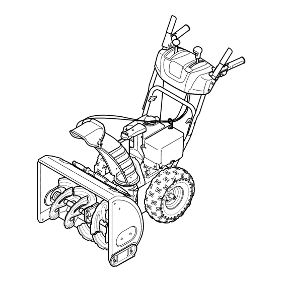
Controls a nd Features Shift Lever Drive Control Chute Directional Control Auger Control Gas Cap Chute Assembly Heated Grips_ Oil Fill Clean Out Tool Muffler RecoU Starter Handle Primer ignition Throttle Control Choke Control Electric Start Augers Button Skid Shoe Oil Drain Electric Starter Outlet... -
Page 12: Auger Control
ThrottleControl AugerControl AUGER CONTROL The throttle control is located on the rear of the engine. regulates the speed of the engine and will shut off the engine when moved into the STOP position. Primer Pressing the primer forces fuel directly %_p_li into the engine's carburetor... - Page 13 Chute Directional Control ChuteClean-OutTool CHUTE DiRECTiONAL CONTROL clogged chute assembly. Shut offengine and remain CHUTE TILT DOWN ARNING! Never use your hands to clear a behind handles until all moving parts have stopped before unclogging. The chute clean-out tool is conveniently fastened to the rear of the auger housing...
-
Page 14: Operation
Operation Plug the extension cord into the electric outlet located Starting the Engine on the engine. Plug the other end of extension cord into a three-prong 120-volt, grounded, AC outlet in a well- ventilated area. See Fig. 5-2. moving parts. Do not use a pressurized starting l_lhllL ARNING! -
Page 15: Replacing Shearpins
RecoilStarter ToEngageDrive With the throttle control in the Fast(rabbit) position, move engine running. shift lever into one of the six forward (F) positions or two CAUTION! Do not pull the starter handle while the reverse (R) positions. Select a speed appropriate for the snow conditions and a pace you're comfortable with. -
Page 16: Maintenance And Adjustments
Maintenance& Adjustments Maintenance Lubrication GearShaft Engine Refer to the Engine Maintenance section. The gear (hex) shaft should be lubricated at least once a season or after every twenty-five (25) hours of operation. ShavePlate and Skid Shoes Allow the engine to run until it is out of fuel. The shave plate and skid shoes on the bottom of the snow Carefully... - Page 17 Auger Shaft Adjustments At least once a season, remove the shear pins from the auger Shift Cable shaft. Spray lubricant inside the shaft and around the spacers and the fla nge bearings found at either end of the shaft. If the full range of speeds (forward and reverse) cannot be See Fig.
-
Page 18: Off-Season Storage
DriveControl Chute DirectionalControl When the drive control is released and in the disengaged "up" If the chute assembly does not have full range from left-to-right, position, the cable should have very little slack. It should NOT be the chute control cables can be adjusted to take up slack: tight. -
Page 19: Engine Maintenance
Engine Maintenance WARNING! To prevent accidental start-up, shut off Periodic inspection and adjustment of the engine is essential high level performance is to be maintained. Regular maintenance the engine and remove the ignition key before will also ensure a long service life. The required service intervals performing any type of engine... -
Page 20: Cleaning The Engine
Check that the spark plug washer is in good condition 5park Plug and thread the spark plug in by hand to prevent cross- threading. plug removed. DO NOT crank engine with spark After the spark plug is seated, tighten with a spark plug WARNING? DO NOT check for spark with spark plug removed. -
Page 21: Belt Replacement
Service Carefully pivot the snow thrower up and forward so that it Belt Replacement rests on the auger housing. Auger Belt Remove the frame cover from the underside of the snow thrower by removing four self-tapping screws which secure To remove and replace your snow thrower's auger belt, proceed it. -
Page 22: Drive Belt
DriveBelt Remove the belt from around the auger pulley, and slip the belt between the support bracket and the auger pulley. To remove and replace your snow thrower's drive belt, proceed See Fig. 8-5. as follows: Place a piece of plastic under the gas cap. Remove the plastic belt cover on the front of the engine by removing the two self-tapping... -
Page 23: Friction Wheelremoval
Friction WheelRemoval Slip the drive belt offthe pulley and between friction wheel and friction wheel disc. See Fig. 8-7. If the snow thrower fails to drive with the drive control engaged, and performing the drive control cable adjustment fails to correct the problem, the friction... - Page 24 Follow the previous steps in reverse order to reassemble Carefully remove the hex nut which secures the hex shaft to components. If you're disassembling the friction wheel and the snow thrower frame and lightly tap the shaft's end to replacing only the rubber ring, proceed as follows: dislodge the ball bearing from the right side of the frame.
-
Page 25: Troubleshooting
Troubleshooting Problem Cause Remedy Engine fails to start 1. Choke not in ON position. 1. Move choke to ON position. 2. Spark plug wire disconnected. 2. Connect wire to spark plug. 3. Fuel tank empty or stale fuel. 3. Fill tankwith clean, fresh gasoline. -
Page 26: Replacement Parts
Replacement P arts Component Part Number and Description 929-0071 Extention Cord, 110V 954-04050 Auger Drive Belt 754-0367 Wheel Drive Belt 684-04153 Friction Wheel Assembly 935-04054 Friction Wheel Rubber 925-04213 Lamp, 12.5V, 37.5W 738-04124A Shear Pin, 1.50 714-04040 Bow-tie Cotter Pin 784-5580 Slide Shoe, Standard (Steel) 731-06439... - Page 28 SECTION NOTES...
- Page 29 SECTION 11 = NOTES...
- Page 30 MTD. OWNER'S WARRANTY RESPONSIBILITIES: As the smalloff-roadengineowner,youare responsible forthe performance of the requiredmaintenance listed in your Owner'sManual.MTD recommends that you retainall yourreceiptscoveringmaintenances on yoursmall off-roadengine,but MTDcan not denywarrantysolelyfor the lack of receiptsor foryour failureto ensurethe performanceto all scheduledmaintenance. As the smalloff-roadengineowner,youshouldhoweverbe awarethat MTDmaydenyyour warrantycoverageif yoursmall off-roadengine or part hasfaileddue toabuse, neglect,impropermaintenance or unapprovedmodifications.
- Page 31 (8)Throughout the engine's warranty period defined inSubsection (a)(2), MTD will m aintain a supply ofwarranted parts s ufficient tomeet the expected demand forsuch parts. (9)Any replacement part m ay b eused i ntheperformance...
-
Page 32: Limited Warranty
MANUFACTURER'S LiMiTED WARRANTY The limited warranty set forth below is given by MTD LLC with c. Service completed by someone other than an authorized service dealer. respect to new merchandise purchased and used in the United States and/or its territories and possessions, and by MTD Products Limited d.
Need help?
Do you have a question about the 600-Series L Style and is the answer not in the manual?
Questions and answers