Table of Contents
Advertisement
Safety • Assembly • Operation • Adjustment • Maintenance • Troubleshooting • Parts Lists • Warranty
OF
A
O
AL
Automatic Lawn Tractor-
Model Series 605
iMPORTANT
READ SAFETY
RULES AND iNSTRUCTiONS
CAREFULLY
BEFORE
OPERATION
Warning:
This unit is equippedwith an internal combustionengineand shouldnot be usedon or nearany unimproved forest-covered, b rush-
coveredor grass-covered land unlesstheengine'sexhaustsystemis equippedwith a sparkarrestermeetingapplicablelocalor statelaws(if any).
If a sparkarresteris used,it shouldbe maintainedin effectiveworkingorder by the operator.In theState of Californiathe aboveis requiredbylaw
(Section4442 of the CaliforniaPublicResources Code). Otherstatesmay havesimilarlaws.Federallaws applyon federallands.A sparkarrester
for the muffleris availablethroughyour nearestengineauthorizedservicedealeror contactthe servicedepartment,RO. Box361131 Cleveland,
Ohio 44136-0019.
PRINTEDIN U.S.A.
MTD LLC, P.O. BOX 361131 CLEVELAND, OHIO 44136-0019
FORMNO.769-02073
11/03/2005
Advertisement
Table of Contents

Related Manuals for MTD 13AT605G755


Summary of Contents for MTD 13AT605G755
- Page 1 If a sparkarresteris used,it shouldbe maintainedin effectiveworkingorder by the operator.In theState of Californiathe aboveis requiredbylaw (Section4442 of the CaliforniaPublicResources Code). Otherstatesmay havesimilarlaws.Federallaws applyon federallands.A sparkarrester for the muffleris availablethroughyour nearestengineauthorizedservicedealeror contactthe servicedepartment,RO. Box361131 Cleveland, Ohio 44136-0019. FORMNO.769-02073 PRINTEDIN U.S.A. 11/03/2005 MTD LLC, P.O. BOX 361131 CLEVELAND, OHIO 44136-0019...
- Page 2 You can locate the model plate by looking beneathe the seat. This information will be necessary to use the manufacturer's web site and/or obtain assistance from the Customer Support MTD LLC Department or an authorized service dealer. P.O= BOX 361131...
- Page 3 Sight and hold this levelwith a vertical tree... >:. also 15° t"b...
- Page 4 WARNING: Engine Exhaust, some of its constituents, and certain vehicle compo- nents contain or emit chemicals known to State of Californiato cause cancer and birth defects or other reproductiveharm. DANGER: This machine was built to be operated according to the rules for safe operation in this manual.
- Page 5 ............ General Operation: 14.Watchfor traffic whenoperatingnearor crossing roadways. T his machineis not intendedfor useon 1. Read,understand,and followall instructionson the anypublic roadway. machineand in the manual(s)beforeattemptingto 15.Do notoperatethe machinewhileunderthe influ- assembleand operate.Keepthis manualin a safe enceof alcoholor drugs. placefor future and regularreferenceand for ordering 16.Mowonly in daylightor good artificiallight.
- Page 6 Do Not: Slope Operation: Slopesare a majorfactor relatedto loss of controland 1. Do notturn on slopesunlessnecessary;then,turn slowlyand graduallydownhill,if possible. tip-overaccidentswhich can resultin severeinjuryor 2. Do not mownear drop-offs,ditchesor embankments. death.All slopesrequireextracaution.If youcannot Themowercouldsuddenlyturnoverif a wheel is over back up the slopeor if youfeel uneasyon it, do notmow the edgeof a cliff, ditch,or if an edge cavesin.
- Page 7 Service 10.Neverattemptto makeadjustmentsor repairsto the machinewhilethe engine isrunning. 1. Neverrun an engineindoors or in a poorlyventilated 11.Grasscatchercomponents and the discharge area. Engineexhaustcontainscarbonmonoxide,an coverare subjectto wearand damagewhich could odorless,and deadlygas. exposemovingpartsor allowobjectsto be thrown. 2. Beforecleaning,repairing,or inspecting,makecertain Forsafety protection, f requentlycheckcomponents the blade(s)and all movingparts havestopped.
- Page 8 IMPORTANT: Y ourtractorisshippedwith motoroil inthe engine.However, y ou MUSTcheckthe oil levelbefore this manualmaynotbe operating.Be careful notto overfill. applicable to all models! MTD LLC reservesthe right to change product spec fications, designs and equipment without notice and without incur- i[ing obligation:...
- Page 9 Shipping Brace Removal WARNING: Make sure the riding mower's engine is off, remove the ignition key, and set the parking brake before removing the ship- ping brace. TractOr • Locatethe shippingbrace,ifpresent,and accompany- ingwarningtag foundon the rightside of the mower, betweenthe dischargechuteand thecuttingdeck. See Figure2.
- Page 10 Attaching The Seat Seatstyles vary bytractormodeland thereare three differentstyles available: • StandardAdjustment • QuickAdjustment& • KnobAdjustment If the seatfor yourtractordid notcome attached,referto Figure4, Figure5, and Figure6 to identifyyourtractor's seat styleand followthe applicableinstructionsbelowto attachit. NOTE:Forshippingreasons,seatsare eitherfastened to the tractorseat'spivot bracketwith a plastictie, or mountedbackwardto the pivot bracket.Ineithercase, freethe seat form its shippingpositionand removethe two hex screws(or knobs,on modelsso equipped)from...
- Page 11 identifying the Mulch Plug (if so ========--_ " On tractormodes soequ pped,amu ch p ug can ether ..", be foundwth n the cutt ng decks d schargeopenng or ',,,, "_ ..[ packedseparatelywith your unit. NOTE: Referto Mulching on page 19for moredetailed LaWn information.
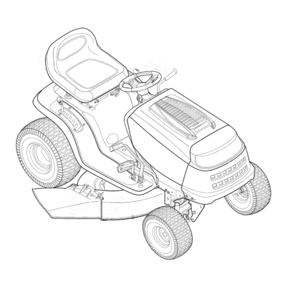
- Page 12 Know Your Lawn Tractor NOTE: Any reference in this manual to the RIGHTor LEFT side of the tractor is observed from operator's position. "_ NOTE:Steeringwheelnot shownfor clarity Figure 8 1-If soequipped SystemsIndicatorMonitor ThrottleLever PTO(Blade Engage)Lever1- CruiseControl Button PTO(Blade Engage)Knob1- IgnitionSwitchModule ChokeKnob1- BrakePedal ParkingBrakeButton...
- Page 13 Throttle Control Lever Thethrottlecontrol lever is locatedon the rightside of Choke Fast thetractor'sdash panel.This levercontrolsthe speed Position Position of the engineand,on somemodels,when pushedall Fast theway forward,the chokecontrol also.Whenset in a Position givenposition,the throttlewill maintaina uniformengine speed.See Figure9. Operating IMPORTANT: W henoperatingthetractorwith the cutting Your LaWn deck engaged,be certainthat the throttleleveris always in the FAST(rabbit)position.
- Page 14 Electric PTO (Blade Engage) Knob (if Equipped) _" BATT. Toengagethe powerto ..rm ..the cuttingdeck or other (separatelyavailable)attach- mentson modelsequipped with an electric PTO,pull 42.0 outwardon the PTO(Blade Engage)knob.Pushthe PTO HOURS 1/10 \\\ Tractor (Blade Engage)knobinward (®) to disengagethe powerto the cuttingdeck. ii_i_i i iii_ii iii_iII ii!iii_i_ _:Ii i_i PTO/ BLADE PARKING...
- Page 15 Parking Brake Button Safety Interlock Switches Toset the parkingbrake,fully This tractorisequippedwith a safetyinterlock s ystem depressthe brakepedal and for the protectionof the operator.Ifthe interlocksystem pushthe parkingbrakebutton in. shouldevermalfunction,do notoperatethe tractor. Contactan authorizedMTDservicedealer. Holdthe button in whiletaking yourfoot off the brakepedal.Both •...
- Page 16 Reverse .Push Button indicator AVOID SERIOUS INJURY OR DEATH Light GO UPAND DOWNSLOPES,NOT ACROSS. Reverse Caution Mode AVOIDSUDDENTURNS. Stop Position Position DO NOT OPERATETHE UNITWHERE IT COULDSLIP OR TIE © Start IF MACHINE STOPSGOINGUPHILL,STOP BLADE(S) AND Position BACK DOWNHILLSLOWLY. DO NOT MOWWHEN CHILDRENOROTHERS AREAROUND. NEVER CARRYCHILDREN,EVENWITH BLADESOFR LOOK DOWNAND BEHIND BEFOREAND WHILE BACKING.
- Page 17 Stopping the Engine away from the discharge opening ARNING: Keep hands and feet of the cutting deck. WARNING: if you strike a foreign object, stop the engine, discon- NOTE:Thedeck wheelsare an anti-scalpfeatureof the nect the spark plug wire(s) and deck and are not designedto supportthe weightof the ground against the engine.
- Page 18 4. Tomovein reverse,placethe shiftleverin the Disengagethecruise controlusingone of the following methods: REVERSEposition,checkthat thearea behindis clearthen slowlydepressthe drivepedal. 1. Depressthe brakepedalto disengagethecruise controland stop the tractor. Driving On Slopes 2. Lightlydepressthe drivepedal. Referto the SLOPEGAUGEon page3 to help deter- Tochangeto the reversedirectionwhenoperatingwith mineslopeswhereyou mayoperatethe tractorsafely.
- Page 19 Thefollowinginformationwill be helpfulwhenusingthe cuttingdeck with yourtractor: WARNING: Plan your mowing pattern to avoid discharge of materials toward roads, side- i ii iiiii iiii _I walks, bystanders and the like. 0 perat in g Also, avoid discharging material Your LaWn against a wall or obstruction which may cause discharged material to ricochet back toward the operator.
- Page 20 Front To Rear Thefront of the cuttingdeck is supportedbya stabilizer bar that canadjustedto levelthe deck from frontto rear. Thefront of the deck shouldbe between1/4-inchand 3/8-inch lowerthanthe rear of the deck.Adjustif neces- sary as follows: 1. With the tractorparkedon a firm,levelsurface,place the deck lift leverin the top notch(highestposition) and rotatethe blade nearestthe dischargechute so that it is parallelwith the tractor.
- Page 21 brakes while the engine is running. __i= ARNING:Neverattemptto adjustthe Alwaysdisengage PTO,moveshift leverinto neutral position,stop engine and remove key to preventunintended starting. Ifthe tractordoesnot cometo a completestop whenthe brakepedal is completelydepressed,or if the tractor's rearwheelscan roll with the parkingbrakeapplied,the brakeis in need of adjustment,Thebrakedisc can be foundon the rightsideof thetransmissionin the rear of the tractor.Adjustif necessaryas follows: 1.
- Page 22 Seat Adjustment Quick Adjust Seat Ofso equipped) machine, make sure the seat is engaged WARNING: Before operatingthis in the seat stop, stand behind the machine and pull back on seat until fully Your LaWn engaged intostop. Toadjustthe positionof the seat on modelsequipped with a seatadjustmentlever,movethe leverto the left and slidethe seat forwardor rearward.See Figure 8 on page 12.Make sureseat is lockedintoposition...
- Page 23 Adjustthe drag links so that equal lengthsare threaded intothe balljointon the left and rightside: 1. Loosenthejamnut foundon the drag linkat the rear of the ball joint.See Figure19. 2. Removehex nuton thetop of balljoint.See Figure19. 3. Threadthe balljoint towardthejam nut to shortenthe drag link.
- Page 24 Performthe abovestepsin the oppositeorder afteroil has finisheddraining. 6. Refillthe enginewith newmotoroil as instructedin the EngineOperator/Owner M anualpackedwith your unit. IMPORTANT: R eferto the EngineOperator/Owner Manualpackedwith yourunit for informationregardingthe quantityand properweight of motoroil. Air Cleaner Servicethe pre-cleaner, i f soequipped,and cartridge/air cleanerelementas instructedin the EngineOperator/ OwnerManualpackedwith your unit.
- Page 25 Deck Wash System ..Yourtractor'sdeck may be equippedwith a waterporton its surfaceas part of itsdeck wash system. Use the DeckWashSystem to rinsegrassclippings fromthe deck'sundersideand preventthe buildupof cor- rosivechemicals.Completethe followingstepsAFTER EACHMOWING: 1. Drivethe tractorto a level,dear spoton yourlawn, nearenoughto a water sillcock(spigot)for your You r Lawn gardenhoseto reach.
- Page 26 8. Movethe deck lift leverintothe top notchon the right Charging fenderto raisedeck lift arms up and out of the way. If the tractorhas not beenput into usefor an extended periodof time,chargethe batterywith an automotive-type NOTE:Modelswith a 46-inchdeck are equippedwith a 12-voltchargerfora minimumof one hour at six amps.
- Page 27 Cutting Blades WARNING: Be sure to shut the engine off, remove ignition key, disconnect the spark plug wire(s) and ground against the engine to prevent unintended starting before removing the cut- ting blade(s) for sharpening or replacement. Protect your hands by using heavy gloves or a rag to grasp the cutting blade.
- Page 28 42" Deck 3. a. Removethe beltkeeperrod fromaroundthe engine pulley. b. Inserta 3/8"-driveratchetwrench(setto loosen) intothe squareholefound inthe idlerbracketon the left side of the deck'ssurface. i ioto °i°g c. Graspthe ratchet'shandleand pivot ittowardthe frontof the tractorto relievetensionon the belt. d. With belttension relieved, c arefullyremovethe belt from around the left-hand spindle pulley.
- Page 29 42" Deck LeftHand EnginePulley SpindlePulley Maintaining Your Lawn Right Hand Tractor Spindle Pulley Idler Figure 26 Engine Puny, 46" Deck PTO Belt (Top) PTO Idler Bracket Deck Idler Deck Belt (Bottom) ® Figure 27...
- Page 30 Cleanand lubricatethe tractoras instructed i n Section Followthe instructions in the Service, Storage & 6: MAiNTAiNiNGYOUR LAWNTRACTORon page 19 Specifications sectionof the EngineOperator/Owner of this manualbeforestoringfor an extendedperiod. Manualfor properenginecare priorto storingyourtractor. WARNING: Never store the an approved containeroutdoors, WARNING" Drain fuel only into achine or fuel container indoors away from an open flame.
- Page 31 DOHOTMOWWHEN CNiLCHEH OROTHERS AREAROUND • NEVER CANNY CHILDREN EVER W iTHRLDN_R} OFF. • LOOK DOWNANDBCHINU BEFCHE A NDWHILE BUCKING. • MOWIHG IN REVERSE iS NOTRECOMMENDED. NOTE: aN BOTH MODES, WHEN OPERATOR LEAVES SEAT,ENGINE WILL WARNING This symbol points out importantsafety instructionswhich, if not followed,could endangerthe personal...
- Page 32 Pro bl e m Ca use Remedy Enginefails to start I 1 PTOengaged. 1 PlacePTOknob(or lever)in disengaged (OFF)position. 2. Sparkplugw re(s)disconnected. 2. Connectwire(s) to spark plug(s). 3 Fueltank em t or stalefuel 3 F tankwth c ean fresh gaso ne •...
- Page 33 Problem Cause Remedy Engine overheats Engine0i!leveliowl Fi!!ciankcasewithpr0peroi!. 21 Air flow restricted. 2 c eangrass clippingsaid debiis fromaroundthe engines co0!ing ..fins and blowerhousing. Enginehesitates at 1. Sparkplug(s)gap tooclose. 1. Removesparkplug(s)and reset high RPM the gap. Idles poorl Sparkpug(s)foued fautyorgap 1 Repacesparkpug(s)Setpug(s) too wide_ gap: 2 Dirtyair €eaner...
- Page 34 iVlodel Series 605 Modelsw/Manually Adjusting Seat Modelsw/Quick AdjustSeat iiiiiiJ ©...
- Page 35 Ref. Part No. Description Ref. PartNo. Description 710-1268t Screw,#10-16x.375 783-1010A Adjust.Brkt, Lift (ModelX605H) 712-04063 Nut, FlangeLock,5/16-18,GrF 783-0677 Adjust.Brkt., Lift 712-3027t Nut, FlangeLock, 1/4-20 783-1489A MountingBracket,Seat 720-0309At SeatAdjusterGrip 710-0227 Screw,#8-18x.50 726-0201t Nut, Speed,.3125 ID 726-0279 Plate,Insulator 731-04074t Spacer 725-1303 SpringSwitch,Outer 732-0499t Compression Spring,.41 x 1.5 725-1439 SpringSwitch,inner...
- Page 36 iVlodel Series 605...
- Page 37 Fief. PartNo. Description 710-04095 Hex Screw,3/8-16, 1.00,Gr5 710-0514 Hex Screw,3/8-16, 1.00,Gr5 710-0643 Hex Screw,5/16-18,1.00,Gr5 711-1408 Link, Drag, RH 711-1409A Link, Drag, LH 712-0214 Nut, Hex Lock,3/8-24 712-04065 Nut, FlangeLock,3/8-16,Grf 712-0459 Nut, FlangeLock,7/16-20 712-3004A Nut, FlangeLock,5/16-18,Gr5 712-0240 Nut,Jam, 7/16-20,Gr2 717-1550E Gear,Steering,11/90Ratio 717-1554 Gear,Pinion,Steering 723-0448A Ball Joint,7/16-20,Lock...
- Page 38 Model Series 605 \\\\\\\\\\\\\\\...
- Page 39 Fief. PartNo. Description Fief. Part No. Description 731-04215 CruiseControlButton 710-0726 Screw,5/16-12x.750 710-0599 Self-tappingScrew,1/4-20x.5 731-04217 ParkingBrakeButton 736-0176 FiatWasher,.265x .938x 1.20 710-0751 Hex CapScrew,1/4-20x.62 Illustrated 746-1084 ThrottleControl/Cable 747-1196 Brake/Cruise Pivot Rod 731-1999 ChokePlug 629-040831- HeadlightWireHarness 731-05165A HoodPlenum 731-04949 HeadlightLens 738-04091 ShoulderScrew,.43 x.29 783-04908 RH DashSupportPlate 783-04551...
- Page 40 iVlodel Series 605 Left HandTransmission Bolt Mounting \\\\...
- Page 41 Fief. PartNo. Description Fief. Part No. Description 17840 MountingBracket,Transaxle 783-04360 Bracket,Shift, F-N-R 725-04039 Switch,Interlock 783-04442 IdlerBracket,CenterDouble 17962 Plate,Switch 647-0031B ControiAssembly,Brake 647-04020 LeverAssembly,Shift 647-0032A ControiAssembly,Speed 710-0607 Screw,5/16-18,0.500 683-0266 PedalAssembly 710-0726 Screw,5/16-12,0.750 710-0650 Screw,5/16-18,0.875 710-0809 Screw,1/4-20, 1.250 710-1260A Screw,5/16-18, 0.750 710-1007 Screw,Seres,3/8-16, 1.500 710-1611B Screw,5/16-18,0.750 710-1266...
- Page 42 iVlodel Series 605 Ref. PartNo. Description 656-04015 PulleyAss'y,VariableSpeed 683-04129 Bracket,Pulley 710-0627 Screw,5/16-24,.750 710-1652 Screw,1/4-20,.625 718-04012 Cup,Bearing 736-0362 Washer,Flat 741-0600 Ball Bearing • 90 _ 783-04722 SwitchBracket,ParkingBrake 736-0242 Washer,Bell,.340x.872x.060 712-04065 Nut,FlangeLock,3/8-16, GrF 710-0599 Screw,1/4-20x.500 736-0430 FlatWasher,.350x1.59x.062 634-0104 WheelAssyComp,20 x 8 x 8 734-1730 Tire Only20 x 8 x 8 To order replacement...
- Page 43 !!! us t rated To order replacement _arts, call the Custome Service Line at 1-800-800-7310, or visit www.mtdproducts.com. Fief. PartNo. Description Fief. PartNo. Description 710-0227 AB Screw#8-18x 0.5 726-0205 HoseClamp 710-0599 TT Screw1/4-20x 0.5 725-0157 CableTie 710-0726 AB Screw5/16-12x 0.5 726-0272 Clamp 783-0615D MufflerBracket...
- Page 44 iVlodel Series 605 IMPORTANT Fora proper working machine, use FactoryApproved Parts. V-belts are designed to engage and disengage safely. A substitute (non OEM) V-belt can be dangerous by not disen a in com letel.
- Page 45 Fief. PartNo. Description Fief. PartNo. Description 17962 Plate,Switch 747-04355 KeeperRod, Belt 647-0064 LeverAssembly,Engagement 747-04470 Engagement H andle,Deck 683-0302 PlateAssembly,Engagement 748-0415B Spacer,.385ID x .635OD x 1.54 710-0224 Screw,#10-16,0.500 710-1260A Screw,5/16-18x.750 Illustrated 710-0276 Screw,Carriage,5/16-18,1.00 756-04207 Pulley,Engine,3.39 x 6.12 Dia. 710-0347 Screw,3/8-16, 1.75,Gr5 756-0487 Pulley,Idler,V-type 5/8 x 4.0 Dia.
- Page 46 Model Series 605 CC?P _ • .._3j ).s_l...
- Page 47 Ref. Part No. Description 732-0614 Ring,Wire 716-0231 Ring, E Type,.750 Parts List 736-0336" FlatWasher,5/8 x 1.0x.030 736-0337" FlatWasher,5/8 x 1.0x.040 736-0349" FlatWasher,5/8 x 1.0x.020 736-0335 Washer,Thrust.635x 1.26x.06 710-1325 Self-tapping Screw,1/4-20x 1.625 719-04017 UpperHousing 711-1109 inputShaft 741-0335 NeedleBearing,.625 x.813x.495 717-1464 14-toothBevelPinion 716-0108 RetainingRing,.437 741-0340...
- Page 48 Model Series 605...
- Page 49 Ref. PartNo. Description Ref. PartNo. Description 732-0429A Spring,Extension,.50 Diax3.97 1 L 17116 Brake Assembly,Deck 17258D RH Belt Cover,Deck46" 732-0594A Spring,Extension,.91 Diax7.33 618-0240A SpindleAssembly,5.00 Dia. 732-04197 Spring,Extension,.68 Diax 5.0 618-04134B SpindleAss'y,DoublePulley 734-0973 Wheel, Deck5.0x 1.38 683-0254B HangerBracketAssembly 736-0119 Washer,Lock,5/16 683-04104A DeckWeldment 736-0760 Washer,Lock 710-0520...
- Page 50 Use this page to make notes and write down important in_orma.on! ,i!_ii_i_i !i_ii_ii_!_i_ i_ii_i_i_i_i_i_i_i_i_i_i_i_i_i_i_i_i_...
- Page 51 Asthe lawn mowerowner,you shouldhoweverbe awarethat MTDLLC maydeny you warrantycoverageif your lawnmoweror a part has failed due to abuse, neglect,or impropermaintenanceor unapprovedmodifications. Youare responsiblefor presentingyourlawn mowerto MTDLLC's distributioncenteror servicecenteras soonas the problemexists.The warrantyrepairsshould be completedin a reasonableamountof time, not to exceed30 days. If you havea questionregardingyourwarrantycoverage,you shouldcontactthe MTD ServiceDepartmentat 1-800-800-7310. GENERAL...
- Page 52 To locate the dealer in your area, check your Yellow Pages, lasts,sothe aboveexclusions or limitations m aynot applyto you. or contact MTD LLC at RO. Box 361131,Cleveland, Ohio 44136- In no event shallrecoveryof any kindbe greaterthanthe amountof the 0019, or call 1-800-800-7310 or 1-330-220-4683 or log on to our purchasepriceof the productsold.Alterationof safety features of...
Need help?
Do you have a question about the 13AT605G755 and is the answer not in the manual?
Questions and answers