Table of Contents
Advertisement
Quick Links
Safe Operation Practices • Set-Up • Operation • Maintenance • Service • Troubleshooting • Warranty
O
'
M
peratOr
s
anual
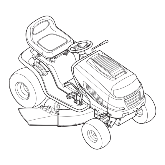
Model Series 600 Lawn Tractor
WARNING
READ AND FOLLOW ALL SAFETY RULES AND INSTRUCTIONS IN THIS MANUAL
BEFORE ATTEMPTING TO OPERATE THIS MACHINE.
FAILURE TO COMPLY WITH THESE INSTRUCTIONS MAY RESULT IN PERSONAL INJURY.
MTD LLC, P.O. BOX 361131 CLEVELAND, OHIO 44136-0019
Printed In USA
Form No. 769-04717A
(January 16, 2009)
Advertisement
Table of Contents

Related Manuals for MTD 13AL605H057


Summary of Contents for MTD 13AL605H057
- Page 1 READ AND FOLLOW ALL SAFETY RULES AND INSTRUCTIONS IN THIS MANUAL BEFORE ATTEMPTING TO OPERATE THIS MACHINE. FAILURE TO COMPLY WITH THESE INSTRUCTIONS MAY RESULT IN PERSONAL INJURY. MTD LLC, P.O. BOX 361131 CLEVELAND, OHIO 44136-0019 Printed In USA Form No. 769-04717A...
-
Page 2: Table Of Contents
Choose from the options below: ◊ Visit us on the web at www.mtdproducts.com ◊ Call a Customer Support Representative at (800) 800-7310 or (330) 220-4683 ◊ Write us at MTD LLC • P.O. Box 361131 • Cleveland, OH • 44136-0019... -
Page 3: Safe Operation Practices
Important Safe Operation Practices WARNING! This symbol points out important safety instructions which, if not followed, could endanger the personal safety and/or property of yourself and others. Read and follow all instructions in this manual before attempting to operate this machine. Failure to comply with these instructions may result in personal injury. - Page 4 A missing or damaged discharge cover can cause blade Slope Operation contact or thrown object injuries. Slopes are a major factor related to loss of control and tip-over Stop the blade(s) when crossing gravel drives, walks, or accidents which can result in severe injury or death. All slopes roads and while not cutting grass.
- Page 5 Children Service Tragic accidents can occur if the operator is not alert to the Safe Handling of Gasoline: presence of children. Children are often attracted to the machine and the mowing activity. They do not understand To avoid personal injury or property damage use extreme the dangers.
- Page 6 Tampering with the governor setting can lead to a runaway do not stop within the this time frame, your machine engine and cause it to operate at unsafe speeds. Never tamper should be serviced professionally by an authorized MTD with factory setting of engine governor. Service Dealer.
- Page 7 Safety Symbols This page depicts and describes safety symbols that may appear on this product. Read, understand, and follow all instructions on the machine before attempting to assemble and operate. Symbol Description READ THE OPERATOR’S MANUAL(S) Read, understand, and follow all instructions in the manual(s) before attempting to assemble and operate DANGER—...
- Page 8 2 — i ectiOn MpOrtant peratiOn ractices...
-
Page 9: Assembly & Set-Up
Shipping Brace Removal to all models. MTD LLC reserves the right to change product specifications, designs and equipment without notice and WARNING! Make sure the riding mower’s engine is without incurring obligation. - Page 10 Attaching The Steering Wheel Attaching The Seat If the steering wheel for your tractor did not come attached, the If the seat for your tractor was not attached at the factory, follow hardware for attaching it has been packed within the steering the instructions below to attach it.
- Page 11 Mulch Plug (if equipped) Service the engine with gasoline and oil as instructed in the separate Engine Operator/Owner Manual packed with your On tractor models so equipped, a mulch plug can be found tractor. Read instructions carefully. within the cutting deck’s discharge opening. IMPORTANT: Your tractor is shipped with motor oil in the NOTE: Refer to Mulching in the “Operation”...
-
Page 12: Controls & Features
Controls and Features PTO (Blade Engage) Lever Drive Pedal Brake Pedal Ammeter Throttle/Choke Lever Ignition Switch Cruise Control Button Parking Brake Button Shift Lever Deck Lift Lever Cup Holder Figure 4-1 Lawn Tractor controls and features are illustrated in Fig 4-1 and described on the following pages. WARNING! Read and follow all safety rules and instructions in this manual, including the entire Operation section, before attempting to operate this machine. - Page 13 Throttle Control Lever Ignition Switch Your new lawn tractor will have one of the following ignition The throttle control lever is located on the right side of the switches. Use Fig. 4-3 to identify which switch your machine tractor’s dash panel. This lever controls the speed of the engine utilizes and follow these instructions for proper operation.
- Page 14 IMPORTANT: Drive Pedal Always set the parking brake when leaving the tractor unattended. The drive pedal is located below the brake pedal Cruise Control Button on the right front side of the tractor along the running board. Depress the drive pedal with The cruise control button is located on the your right foot when the tractor shift lever is in tractor dash panel to the left of the ignition...
-
Page 15: Operation
Use extreme caution while operating malfunction, do not operate the tractor. Contact an authorized the tractor in the REVERSE CAUTION MODE. Always MTD service dealer. look down and behind before and while backing. Do • The safety interlock system prevents the engine from... - Page 16 Activate the choke by moving the throttle into the choke Reverse position. Push Turn the ignition key clockwise to the START position. After Button Indicator the engine starts, release the key. It will return to the ON Light position. IMPORTANT: Do NOT hold the key in the START position for Reverse longer than ten seconds at a time.
- Page 17 WARNING: way forward into the engaged (ON) position. Do not mow on inclines with a slope in excess of 15 degrees (a rise of approximately 2-1/2 IMPORTANT: The engine will automatically shut off if the PTO feet every 10 feet). The tractor could overturn and lever is engaged with the shift lever in position for reverse travel.
- Page 18 Mulching (If So Equipped) Select models come equipped with a mulch kit which incorporates special blades, already standard on the tractor, in a process of recirculating grass clippings repeatedly beneath the cutting deck. The ultra-fine clippings are then forced back into the lawn where they act as a natural fertilizer.
-
Page 19: Maintenance & Adjustment
Maintenance & Adjustments Maintenance The engine is equipped with either a twist-and-pull drain port or a tabbed drain port. If your engine has the twist- WARNING: Before performing any maintenance or and-pull drain go to step a. If your engine is equipped with repairs, disengage PTO, move shift lever into neutral the tabbed drain go to step b. - Page 20 Front Axles Battery Failures Some common causes for battery failure are: Each of the front wheel axles and rims is equipped with a grease fitting. See Fig. 6-2. Lubricate with a No. 2 multi-purpose grease • Incorrect initial activation applied with a grease gun after every 25 hours of tractor operation. •...
- Page 21 Front To Rear The front of the cutting deck is supported by a stabilizer bar that can be adjusted to level the deck from front to rear. The front of Adjustment the deck should be between 1/4-inch and 3/8-inch lower than Gear the rear of the deck.
- Page 22 Replace hex nut after the proper adjustment is achieved. Parking Brake Adjustment NOTE: Threading the ball joints too far onto the drag links WARNING: Never attempt to adjust the brakes will cause the front tires to “toe-in” too far. Proper toe-in is while the engine is running.
-
Page 23: Service
Service Cutting Deck Removal Note: Note what hole the other end of the belt-keeper rod is inserted into for reinstallation purposes. To remove the cutting deck, proceed as follows: Remove the belt (C) from around the tractor’s engine Place the PTO/Blade Engage lever in the disengaged (OFF) pulley and idler pulley(s). - Page 24 Remove the hex flange nut that secures the blade to the spindle assembly. See Fig. 7-5. To properly sharpen the cutting blades, remove equal amounts of metal from both ends of the blades along the cutting edges, parallel to the trailing edge, at a 25°- to 30° angle.
- Page 25 Several components must be removed and special tools used in this manual). order to change the tractor’s transmission drive belt. See your authorized MTD service dealer to have the transmission drive Set the tractor’s parking brake before removing the jumper belt replaced.
- Page 26 NOTE: Several components must be removed in order to change the tractor’s lower deck belt. See an authorized MTD Service All belts on your tractor are subject to wear and should be Dealer to have your lower drive belt replaced or phone Customer replaced if any signs of wear are present .
-
Page 27: Troubleshooting
Troubleshooting Problem Cause Remedy Engine fails to start PTO/Blade Engage knob engaged. Place knob in disengaged (OFF) position. Parking brake not engaged. Engage parking brake. Spark plug wire disconnected. Connect wire to spark plug. Throttle control lever not in correct starting Place throttle lever to FAST position. -
Page 28: Replacement Parts
NOTE: This Operators Manual covers a range of product specifications for various models. Characteristics and features discussed and/or illustrated in this manual may not be applicable to all models. MTD LLC reserves the right to change product specifications, designs and equipment without notice and without incurring obligation. -
Page 29: Attachments & Accessories
Attachments & Accessories The following attachments and accessories are compatible for all 600 series lawn tractors. See the retailer from which you purchased your tractor, or call the contact number on page 2, for information regarding price and availability. CAUTION: The 600 series lawn tractors are NOT designed for use with any type of ground-engaging attachments (e.g. -
Page 30: Warranty
MTD Consumer Group Inc cannot deny warranty solely for the lack of receipts. As the lawn mower owner, you should however be aware that MTD Consumer Group Inc may deny you warranty coverage if your lawn mower or a part has failed due to abuse, neglect, or improper maintenance or unapproved modifications. - Page 31 WARRANTED PARTS: The repair or replacement of any warranted part otherwise eligible for warranty coverage may be excluded from such warranty coverage if MTD Consumer Group Inc demonstrates that the lawn mower has been abused, neglected, or improperly maintained, and that such abuse, neglect, or improper maintenance was the direct cause of the need for repair or replacement of the part.
- Page 32 MANUFACTURER’S LIMITED WARRANTY FOR The limited warranty set forth below is given by MTD LLC with c. Routine maintenance items such as lubricants, filters, blade respect to new merchandise purchased and used in the United States sharpening, tune-ups, brake adjustments, clutch adjustments,...
Need help?
Do you have a question about the 13AL605H057 and is the answer not in the manual?
Questions and answers