Table of Contents
Advertisement
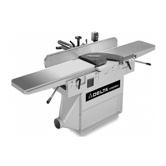
DJ-30 12" Jointer
(Model 37-360, Three Phase)
(Model 37-361, Single Phase)
PART NO. 1349482 - 02-06-04
Copyright © 2004 Delta Machinery
To learn more about DELTA MACHINERY
visit our website at: www.deltamachinery.com.
For Parts, Service, Warranty or other Assistance,
1-800-223-7278 (
1-800-463-3582).
please call
In Canada call
Advertisement
Table of Contents

Subscribe to Our Youtube Channel
Related Manuals for Delta 37-360


Summary of Contents for Delta 37-360
- Page 1 DJ-30 12” Jointer (Model 37-360, Three Phase) (Model 37-361, Single Phase) PART NO. 1349482 - 02-06-04 Copyright © 2004 Delta Machinery To learn more about DELTA MACHINERY visit our website at: www.deltamachinery.com. For Parts, Service, Warranty or other Assistance, 1-800-223-7278 ( 1-800-463-3582).
-
Page 2: Safety Guidelines - Definitions
SAFETY GUIDELINES - DEFINITIONS This manual contains information that is important for you to know and understand. This information relates to protect- ing YOUR SAFETY and PREVENTING EQUIPMENT PROBLEMS. To help you recognize this information, we use the symbols below. Please read the manual and pay attention to these sections. Indicates an imminently hazardous situation which, if not avoided, will result in death or serious injury. - Page 3 GENERAL SAFETY RULES FAILURE TO FOLLOW THESE RULES MAY RESULT IN SERIOUS INJURY. 1. FOR YOUR OWN SAFETY, READ THE INSTRUCTION MANUAL BEFORE OPERATING THE MACHINE. Learning the machine’s application, limitations, and specific hazards will greatly minimize the possibility of accidents and injury.
-
Page 4: Additional Safety Rules For Jointers
ADDITIONAL SAFETY RULES FOR JOINTERS FAILURE TO FOLLOW THESE RULES MAY RESULT IN SERIOUS INJURY. DO NOT OPERATE THIS MACHINE until it is completely assembled and installed according to the instructions. A machine incorrectly assembled can cause serious injury. OBTAIN ADVICE from your supervisor, instructor, or another qualified person if you are not thoroughly familiar with the operation of this machine. -
Page 5: Power Connections
A separate electrical circuit should be used for your machines. This circuit should not be less than #12 wire and should be protected with a 20 Amp time lag fuse. If an extension cord is used, use only 3-wire extension cords which have 3- prong grounding type plugs and matching receptacle which will accept the machine’s plug. -
Page 6: Three Phase Operation
Delta Model 37-360 and 37-361 (DJ-30) are 12" Precision Jointers with a cutting capacity of 12" (304mm) wide, 3/4" deep (19mm max.) and 3/4" (19mm) rabbeting. Model 37-360 includes a three-phase 3 HP motor that is wired for 220V (can be wired at 460V). Model 37-361 includes a single phase 3 HP motor wired for 230V. Both include a fence, three- knife cutterhead, cutterhead guard, and push blocks. - Page 7 DEFINITIONS OF JOINTING AND PLANING OPERATIONS JOINTING OPERATIONS – Jointing cuts or edge jointing is the simplest and most common operation which can be done on the jointer and these cuts are made to square an edge of a workpiece. The fence is square with the table and the depth of cut is approximately 1/8 inch.
-
Page 8: Unpacking And Cleaning
UNPACKING AND CLEANING Carefully unpack the machine and all loose items from the shipping container(s). Remove the protective coating from all unpainted surfaces. This coating may be removed with a soft cloth moistened with kerosene (do not use acetone, gasoline or lacquer thinner for this purpose). After cleaning, cover the unpainted surfaces with a good quality household floor paste wax. - Page 9 REMOVING MACHINE FROM SHIPPING SKID Fig. 6 1. Open door (A) Fig. 5, under infeed table and remove mounting hardware that fastens infeed end of machine to skid 2. Remove three screws (B) Fig. 6, and remove cover (C) from dust chute located under outfeed table. Remove mounting hardware located inside cover (C) that fastens outfeed end of machine to skid and replace cover (C).
- Page 10 ASSEMBLING DUST HOOD 1. Assemble the dust hood (A) Fig. 8, to the outfeed end of the jointer base using the seven 5/8″ long button head screws (B) as shown. MOVING START-STOP SWITCH TO THE UP POSITION 1. For shipping purposes, the start-stop switch and switch arm (A) is shipped in the down position, as shown in Fig.
- Page 11 SINGLE PHASE INSTALLATION IMPORTANT: The jointer cutterhead is a high inertia load which causes the motor to draw a high inrush current during starting. The jointer must be connected to an electrical circuit protected by a properly sized fuse or circuit breaker to handle this high inrush of current. We recommend either a 30 Amp time lag fuse, or a 40 Amp motor start circuit breaker.
-
Page 12: Three Phase Installation
THREE PHASE INSTALLATION If the motor on your machine is wired for 200, 230 or 460 Volts, Three Phase, proceed as follows when connecting your machine to an electrical power system. 1. Remove screw (A) Fig. 15, and terminal strip cover (B). -
Page 13: Operating Controls And Adjustments
OPERATING CONTROLS AND ADJUSTMENTS START-STOP SWITCH The start-stop switch is conveniently located on a post, behind the jointer fence, for easy accessibility. To start the machine, simply press the start button (A) Fig. 18, and to stop the machine, press the stop button (B). FENCE OPERATION 1. - Page 14 ADJUSTING FENCE POSITIVE STOPS The fence on your jointer is equipped with positive stops at the most used fence positions of 90 degrees and 45 degrees right and left. To check and adjust the positive stops, proceed as follows: 1. Position the fence 90 degrees to the table making sure end of stop screw (A) is against stop (B) as shown in Fig.
- Page 15 5. Tilt the fence outward as far as possible and using a combination square (F) Fig. 26, check to see if the fence is tilted outward 45 degrees to the table, as shown. NOTE: 90 degree stop (B) must be rotated up in order to tilt the fence outward.
-
Page 16: Adjusting Belt Tension
OUTFEED TABLE ADJUSTMENTS For most jointing operations the outfeed table must be exactly level with the knives at their highest point of revolution. To move the outfeed table, loosen lock handle Fig. 30, and move the table raising and lowering hand lever (B) up or down until the table is level with the knives. -
Page 17: Cutterhead Guard
4. To adjust belt tension, turn nuts (F) and (G) Fig. 34, to move motor plate (H) up or down until there is approximately 1/2 inch deflection at the center span of the belts, as explained in STEP 3. ADJUSTING SPRING TENSION OF CUTTERHEAD GUARD The cutterhead guard (A) Fig. -
Page 18: Operation
CUTTERHEAD ROTATION The rotation of the cutterhead must be in a clockwise direction when viewed from the left side of the machine; that is, the knives must be rotating toward the infeed table from the top. If the cutterhead rotation is incorrect, disconnect the machine from the power source and proceed as follows: Single Phase Machines –... -
Page 19: Jointing An Edge
JOINTING AN EDGE This is the most common operation for the jointer. Set the guide fence square with the table. Depth of cut should be the minimum required to obtain a straight edge. Hold the best face of the piece firmly against the fence throughout the feed as shown in Fig. -
Page 20: Taper Cuts
TAPER CUTS One of the most useful jointer operations is cutting an edge to a taper. The method can be used on a wide variety of work. Tapered legs of furniture are a common example. Instead of laying the piece on the infeed table, lower the forward end of the work onto the outfeed table. Do this very carefully, as the piece will span the knives and they will take a “bite’”... -
Page 21: Maintenance
REMOVING, REPLACING AND SETTING KNIVES If the knives are removed from the cutterhead for replacement or regrinding, care must be used in removing, replacing and resetting them as follows: 1. DISCONNECT THE MACHINE FROM THE POWER SOURCE. 2. Move the fence to the right until it is clear of the cutterhead. 3. - Page 22 7. IMPORTANT: For ease in rotating the cutterhead during the knife setting operation, pull outward on latch (H) Fig. 46, and open hinged access door (J). This provides access to the cutterhead pulley (K) Fig. 47, and belt (L) allowing you to rotate the cutterhead. After knives are adjusted, make certain the access door (J) is in the closed and locked position.
-
Page 23: Parts, Service Or Warranty Assistance
KEEP MACHINE CLEAN Periodically blow out all air passages with dry compressed air. All plastic parts should be cleaned with a soft damp cloth. NEVER use solvents to clean plastic parts. They could possibly dissolve or otherwise damage the material. Wear ANSI Z87.1 safety glasses while using compressed air. - Page 24 PORTER-CABLE (CENTROS DE SERVICIO DE PORTER-CABLE Parts and Repair Service for Porter-Cable (Obtenga Refaccion de Partes o Servicio para su Herramienta en los Siguientes Centros de Porter-Cable ARIZONA Tampa 33609 Tempe 85282 (Phoenix) 4538 W. Kennedy Boulevard 2400 West Southern Avenue Phone: (813) 877-9585 Suite 105 Fax: (813) 289-7948...
Need help?
Do you have a question about the 37-360 and is the answer not in the manual?
Questions and answers