Table of Contents
Advertisement
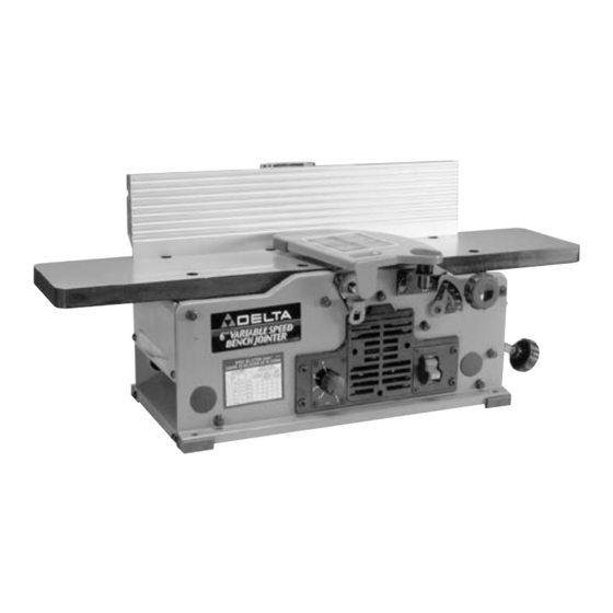
6" Variable Speed
Bench Jointer
(Model 37-070)
PART NO. 901609 (013)
Copyright © 2001 Delta Machinery
To learn more about DELTA MACHINERY
ESPAÑOL: PÁGINA 21
visit our website at: www.deltamachinery.com.
For Parts, Service, Warranty or other Assistance,
1-800-223-7278 (
1-800-463-3582).
please call
In Canada call
Advertisement
Table of Contents

Related Manuals for Delta 37-070


Summary of Contents for Delta 37-070
- Page 1 6" Variable Speed Bench Jointer (Model 37-070) PART NO. 901609 (013) Copyright © 2001 Delta Machinery To learn more about DELTA MACHINERY ESPAÑOL: PÁGINA 21 visit our website at: www.deltamachinery.com. For Parts, Service, Warranty or other Assistance, 1-800-223-7278 ( 1-800-463-3582).
- Page 2 If you have any questions relative to a particular application, DO NOT use the machine until you have first contacted Delta to determine if it can or should be performed on the product.
- Page 3 24. THE USE of attachments and accessories not rec- ommended by Delta may result in the risk of injuries. 25. IMPORTANT: When the tool is not in use, the switch should be locked in the “OFF” position to prevent unauthorized use.
-
Page 4: Grounding Instructions
CONNECTING TOOL TO POWER SOURCE A separate electrical circuit should be used for your tools. This circuit should not be less than #12 wire and should be protected with a 20 Amp time lag fuse. If an extension cord is used, use only 3-wire extension cords which have 3- prong grounding type plugs and 3-hole receptacles which accept the tool’s plug. -
Page 5: Extension Cords
FOREWORD Delta Model 37-070 is a 6" Variable Speed Bench Jointer with designed cutting capacity of 6" (152mm) width and 1/8" (3mm) depth. Unit includes; 10 amp, 120 volt motor with variable speed range from 6000 to 11,000 rpm and cutting speed range from 12,000 to 22,000 cpm, dust chute, center-mounted fence, two-knife cutterhead, cutterhead guard and lock, wrenches and push blocks. - Page 6 JOINTING AND PLANING OPERATIONS Fig. 2 1. JOINTING OPERATIONS – Jointing cuts or edge jointing are made to square an edge of a workpiece. The workpiece is positioned on the jointer with the narrow edge of the workpiece on the infeed table and the major flat surface of the workpiece against the fence, as shown in Fig.
- Page 7 1 - Jointer 2 - Fence 3 - Fence Sliding Bracket 4 - Special Nut (for assembling Fence Sliding Bracket to Fence Mounting Bracket) 5 - Flat Washer (for assembling Fence Sliding Bracket to Fence Mounting Bracket) 6 - Spring Loaded Lock Handle (for assembling Fence Sliding Bracket to Fence Mounting Bracket) 7 - 5/8"...
- Page 8 ASSEMBLY INSTRUCTIONS WARNING: FOR YOUR OWN SAFETY, DO NOT CONNECT THE TOOL TO THE POWER SOURCE UNTIL THE MACHINE IS COMPLETELY ASSEMBLED AND YOU HAVE READ AND UNDERSTAND THE ENTIRE OWNERS MANUAL. ASSEMBLING FENCE 1. Assemble the fence mounting bracket (A) Fig. 5, to the jointer base using the four 5/8"...
- Page 9 3. Assemble 5/8" long socket button head screw (G) Fig. 9, to fence tilting bracket (H) and thread T-nut (J) onto threaded end of screw (G) as shown. DO NOT COMPLETELY TIGHTEN SCREW (G) AT THIS TIME. Assemble screw and T-nut to opposite end of tilting bracket in the same manner.
- Page 10 ASSEMBLING CUTTERHEAD GUARD 1. Thread the two 7/16" long socket button head screws (A) Fig. 13, into the two threaded holes in front side of jointer base. DO NOT COMPLETELY TIGHTEN SCREWS (A) AT THIS TIME. 2. Assemble guard mounting bracket (B) Fig. 14, to the two screws (A) as shown, and tighten the two screws (A).
- Page 11 FASTENING JOINTER TO SUPPORTING SURFACE If during operation, there is any tendency for the jointer to tip over, slide or walk on the supporting surface, the jointer must be secured to the supporting surface with fasteners through the four holes, two of which are shown at (A) Fig.
-
Page 12: Fence Adjustments
VARIABLE SPEED CONTROL Your jointer is supplied with a variable speed control knob (A) Fig. 23, that enables you to operate the machine at cutterhead speeds between 6000 and 11,000 RPM. Speed indicators of 1-2-3-4 and 5 are provided on the speed dial as shown. - Page 13 3. The fence features adjustable positive stops at the most used fence positions of 90 degrees and 45 degrees to the right. To check and adjust the positive stops, proceed as follows: 4. Place a square (C) Fig. 26, on the table with one end of the square against the fence as shown.
- Page 14 When it becomes necessary to adjust the knives due to replacement or wear, proceed as follows: Fig. 30 1. DISCONNECT THE TOOL FROM THE POWER SOURCE AND REMOVE CUTTERHEAD GUARD. 2. Rotate cutterhead and loosen four screws (A) Fig. 30. NOTE: Do not overly loosen the screws (A). Loosen one half turn or only enough so knife can slide between locking plate and cutterhead.
- Page 15 8. If the knives are set too high, the work will be gouged at the end of the cut, as shown in Fig. 33. 9. As a final check, run a piece of work slowly over the knives for 6 to 8 inches. The wood should rest firmly on both tables as shown in Fig.
-
Page 16: Push Blocks
PUSH BLOCKS A set of push blocks (A) Fig. 37, is supplied with your jointer and should be used whenever possible to minimize all danger to your hands. Fig. 37, illustrates using the push blocks properly. The following directions will give the beginner a start on jointer operations. Use scrap pieces of lumber to check the settings and to get the feel of the operations before attempting regular work. -
Page 17: Direction Of Grain
PLANING WARPED PIECES If the wood to be planed is dished or warped, take light cuts until the surface is flat. Avoid forcing such material down against the table; excessive pressure will spring it while passing the knives, and it will spring back and remain curved after the cut is completed. - Page 18 BELT REPLACEMENT When it becomes necessary to replace the belt on your jointer, proceed as follows: 1. DISCONNECT THE TOOL FROM THE POWER SOURCE. 2. Remove screw (A) Fig. 43, using Allen wrench supplied, and remove belt guard (B). 3. Loosen three screws (C) Fig. 44, to release belt tension and remove belt (D) from pulleys.
- Page 19 Delta Building Trades and Home Shop Machinery Delta will repair or replace, at its expense and at its option, any Delta machine, machine part, or machine accessory which in normal use has proven to be defective in workmanship or material, provided that the customer returns the product prepaid to a Delta factory service center or authorized service station with proof of purchase of the product within two years and provides Delta with reasonable opportunity to verify the alleged defect by inspection.
- Page 20 NOTES...
- Page 21 Parts and accessories for Porter-Cable Delta products should be obtained by contacting any Porter-Cable Delta Distributor, Authorized Service Center, or Porter-Cable Delta Factory Service Center. If you do not have access to any of these, call 888-848-5175 and you will be directed to the nearest Porter-Cable Delta Factory Service Center. Las Estaciones de Servicio Autorizadas están ubicadas en muchas grandes ciudades.
Need help?
Do you have a question about the 37-070 and is the answer not in the manual?
Questions and answers