
Related Manuals for Delta DJ-30


Summary of Contents for Delta DJ-30
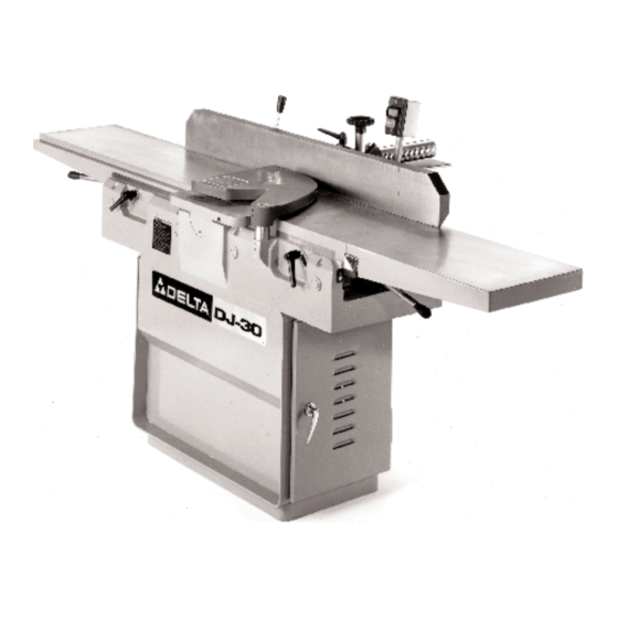
- Page 1 DJ-30 12 Jointer (Model 37-360, Three Phase) (Model 37-361, Single Phase) REVISED 9-7-98 PA RT NO. 1349482 'Delta International Machinery Corp. 1998...
-
Page 2: Table Of Contents
TA B L E O F C O N T E N T S SAFETY RULES ..............3 ADDITIONAL SAFETY RULES F O R JOINTERS . -
Page 3: Safety Rules
If you have any questions relative to a particular applica- tion, DO N O T use the machine until you have first contacted Delta to determine if it can or should be performed on the product. -
Page 4: Additional Safety Rules For Jointers
ADDITIONAL SAFETY RULES FOR JOINTERS 1 . W ARNING: D o n o t o p e r a t e t h e j o i n t e r u n t i l i t i s 1 5 . -
Page 5: Definitions O F Jointing A N D Planing O P E R Ations
DEFINITIONS O F JOINTING A N D PLANING O P E R ATIONS F i g . 2 JOINTING O P E R ATIONS Jointing cuts or edge jointing is the simplest and most common operation which can be done on the jointer and these cuts are made to square an edge of a workpiece. The fence is square with the table and the depth of cut is approximately 1/8 inch. -
Page 6: U N Packing
U N PACKING REMOVING SHIPPING CRATE Your new 12 Jointer is shipped complete in one wooden shipping crate. Remove the crate from around the machine leaving the bottom of the machine fastened to the shipping skid at this time. Remove the fence assembly, dust hood and all loose items from the shipping crate. Figure 4 illustrates all the loose items supplied with your machine. -
Page 7: Removing Machine From Shipping Skid
REMOVING MACHINE F R O M SHIPPING SKID 1 . Open door (A) Fig. 5, under infeed table and remove mounting hardware that fastens infeed end of machine t o s k i d . F i g . 5 2 . -
Page 8: Selecting Floor Spa C E
SELECTING FLOOR SPA C E I t i s i m p o r tant that the machine be set on a solid, level foundation. If rocking occurs, place metal shims at the corners between the base and the floor. Lag screws or bolts may be used if desired to secure the machine to the floor using the same holes that fastened the machine to the shipping skid. -
Page 9: Electrical Connections
ELECTRICAL CONNECTIONS The electrical rating of the DJ-30 12 Jointer is either 230 Volt, single phase, or 200-230/460 Vo l t , t h r e e phase. Before connecting your machine to an electrical power system, be sure the electrical rating of the jointer agrees with the rating of the power system. -
Page 10: Three Phase Installation
THREE P H A S E INSTALLATION If the motor on your machine is wired for 200, 230 or 460 Vo l ts , Three Phase, proceed as follows when connecting your machine to an electrical power system. 1 . Remove screw (A) Fig. 15, and terminal strip cover ( B ) . -
Page 11: O P E R Ating C O N T R O L S A N D Adjustments
O P E R ATING C O N T R O L S A N D ADJUSTMENTS STA R T-STO P SWITCH The start-stop switch is conveniently located on a post, behind the jointer fence, for easy accessibility.To s ta r t the machine, simply press the start button (A) F i g . -
Page 12: Adjusting Fence Positive Stops
ADJUSTING FENCE POSITIVE STO P S The fence on your jointer is equipped with positive stops a t the most used fence positions of 90 degrees and 45 degrees right and left . To check and adjust the positive stops, proceed as follows: 1 . -
Page 13: Infeed Table Adjustments
5 . Tilt the fence outward as far as possible and using a combination square (F) F i g . 2 6 , c h e c k t o s e e i f t h e f e n c e i s tilted outward 45 degrees to the table, as shown. -
Page 14: Outfeed Table Adjustments
OUTFEED TABLE ADJUSTMENTS For most jointing operations the outf e e d table must be e x a c t l y l e v e l w i t h t h e k n i v e s a t t h e i r h i g h e s t p o i n t o f r e v o l u- t i o n . -
Page 15: Adjusting Spring Tension Of Cutterhead Guard
4 . To a d j u s t b e l t t e n s i o n , t u r n n u ts ( F ) and (G) F i g . 3 4 , t o move motor plate (H) up or down until there is approxi- mately 1/2 inch deflection at the center spa n o f t h e b e l ts , as explained in STEP 3. -
Page 16: Jointing An Edge
JOINTING AN EDGE This is the most common operation for the jointer. S e t t h e guide fence square with the table. Depth of cut should be the minimum required to obta i n a s t r a i g h t e d g e . Hold the best face of the piece firmly against the fence throughout the feed as shown in Fig. -
Page 17: Taper Cuts
TA P E R CUTS One of the most useful jointer operations is cutting an edge to a taper. The method can be used on a wide variety of work. Tapered legs of furniture are a common example. Instead of laying the piece on the infeed table, lower the forward end of the work onto the outf e e d table. Do this very care- f u l l y, a s t h e p i e c e w i l l s pa n t h e k n i v e s a n d t h e y w i l l take a bite from the work, with a tendency to kickback unless the piece is firmly held. -
Page 18: Maintenance
MAINTENANCE REMOVING, REPLACING A N D SETTING KNIVES If the knives are removed from the cutterhead for replacement or regrinding, care must be used in removing, replacing and resetting them as follows: 1 . DISCONNECT T HE MACHINE FROM TH E P O W E R S O U R C E. 2 . - Page 19 7 . IMPORTA N T:For ease in rotating the cutterhead during the knife setting operation, pull outward on latch Fig. 46 ( H ) Fig. 46, and open hinged access door (J). This pro- vides access to the cutterhead pulley (K) Fig. 47, and b e l t ( L ) allowing you to rotate the cutterhead.
-
Page 20: W A R R A N T Y
Delta Machinery Delta w i l l r e pa i r o r r e p l a c e , a t i ts expense and at its option, any Delta machine, machine part, or machine accessory which in normal use has proven to be defective in workmanship or material, provided that the...
Need help?
Do you have a question about the DJ-30 and is the answer not in the manual?
Questions and answers