Table of Contents
Advertisement
Advertisement
Table of Contents

Related Manuals for Craftsman 502.255070


Summary of Contents for Craftsman 502.255070
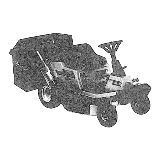
- Page 1 Moden 502=255070 I 0 HPoELECT C START 30" CAUTnON: Read And Follow 5 $P All Safety Rules EAR E G And instructions Before Operating This Equipment. Assembly Operation Customer Responslbiaities Service And Adjustment ulu_ F-93602 Sears, Roebuck and Co., Hoffman Estates, IL. 60179 U.S.A. Printed inUSA.
-
Page 2: Table Of Contents
TABLE OF CONTENTS OPERATING TIPS ........WARRANTY ........MOWING AND BAGGING TIPS ......CUSTOMER RESPONSIBILITIES ....MULCHING TIPS ........PRODUCT SPECIFICATIONS ......CUSTOMER RESPONSIBILITIES ....SAFETY RULES ........MAIN'rENANCE CHART ....... ACCESSORIES AND ATTACHMENTS ....CHECK THE TIRES ........ASSEMBLY ........ -
Page 3: Customer Responsibilities
A Sears Maintenance Agreement is available on this unit See the Operate the unit only with guards, shields and other safety nearest Sears Store for information, items in place and working correctly, PRODUCT SPECIFICATIONS Craftsman Engine ..10 HP, Rear Engine Rider Charging System .. -
Page 4: Safety Rules
SAFETY RULES Safe Operation Practices for Riding Vehicles As Recommended by American National Standards Institute WARNING: This cutting machine is capable of amputating hands and feet andthrowing objects. Failure to observe the following safety instructions could result in serious injury or death to the operator or bystanders. GENERAL OPERATION: Read, understand and follow all instructions in the Instruction Book, on the machine, the engine and with any attachments before... - Page 5 CHILDREN: Tragic accidents can occur if the operator is not alert to the presence of children. Children are often attracted to the machine and the mowing activity,, NEVER assume that children will remain where you last saw them. Keep children out of the mowing area and in the watchful care of an adult other than the operator. Be alert and turn the engine off if children enter the area.
-
Page 6: Accessories And Attachments
ACCESSORIES AND ATTACHMENTS ........, i ill ACCESSORIES AND ATTACHMENTS These accessories and attachments were available when the unitwas purchased_ They are also available at mostSears retail outlets, catalogand service centers.Most Searsstores can orderthese itemsfor you when you providethe model number of your ridingmower. ENGINE MAINTENANCE SPARKPLUG... -
Page 7: Assembly
ASSEMBLY PREPARATION The unit is completely assembled except for the items shown in Figure 1. These items are in the carton along with a parts bag. The parts bag contains the fasteners needed to complete the assembly of the unit, Find and remove these items Do not discard any parts or material until the unit is assembled. -
Page 8: How To Prepare And Charge The Battery
ASSEMBLY PREPARE CHARGE THE BATTERY Wait 20 to30 minutes beforeyou put the vent caps on the battery. While you wait, you can continue with the assembly of WARNING: Read the instructions included with the the unit, battery acid container° Protect your hands and eyes The level of the battery acid can drop belowthe vent described from the battery acid°... -
Page 9: How To Assemble The Steering Wheel
ASSEMBLY HOW TO ASSEMBLE THE STEERING WHEEL Remove the clear tape from the center of the steering wheel Use the fasteners shown below to install the steering wheel The fasteners are shown at full size 15x88 lx102 SteeringWheel Make sure the front wheels point forward Some models have an optional bellows Slide the bellows Bellows... -
Page 10: How To Install The Battery
ASSEMBLY HOW TO INSTALL THE BATTERY Use the fasteners shown below to install the battery, The fasteners are shown at full size. 91565 Battery Clamp 32618 Battery Tray 15x66 lx38 Figure 6 Attach the drain tube to the bottom of the battery tray (Figure 6)°... -
Page 11: How "To Install The Sem
ASSEMBLY HOW TO INSTALL THE SEAT Use the fasteners shown below to install the seat The fasteners are shown at full size Seat Bracket 1x45 I8x16 2x53 15x88 Set the seat bracket on the seat support (Figure 9). Pull the wire harness between the seat hinge and the seat bracket Figure 9... - Page 12 ASSEMBLY The following parts and fasteners are for assembly of the grass bagger. Remove and check the contents of Box A and Box B. CONTENTS OF BOX A ExtensionTube Elbow CONTENTS OF BOX B Window Hinge PartsBag FrontWeight Center Tube Frame Bracket Channel Support Bracket...
- Page 13 ASSEMBLY GRASS BAGGER PARTS BAG - CONTENTS The fasteners and other loose parts are shown below. The fasteners are shown at full size The quantity is shown in brackets On some models, all of the fasteners are not required 5/16"-24xl 5/8"...
-
Page 14: How To Mounlr The Frame Assembly
ASSEMBLY HOW TO MOUNT THE FRAME ASSEMBLY Mount the center tube to the channel (Figure 14)_ Make sure the fasteners are tighL iMPORTANT: Note the bolt in Figure 11 that was installed at the Attach the caps to the ends of the tubes (Figure 14). -
Page 15: How To Mount The Cover
ASSEMBLY HOW TO MOUNT THE COVER Assemble the hinge to the cover (Figure 15)_ The fasteners Handle are shown full size belowr Push the hinge toward the top of the cover, Make sure the screws are at the bottom of the holes in the hinge. -
Page 16: How To Mount The Extension Tube
ASSEMBLY HOW TO MOUNT THE EXTENSION TUBE Attach latch pin (A) to the extension tube with the fasteners shown full size below,_ (Not Shown Full Size) 54563 15X89 2X39 14x86 Disconnect the wire from the spark plug., Raise the deflector, Rotate the blade away from the discharge opening., careful of the position of the blade. -
Page 17: How To Mount The Connector Tube
ASSEMBLY HOW TO MOUNT THE CONNECTOR TUBE Align the tab with the hole Mount the connector tube with the fasteners shown full size below. Elbow Connector] 26x239 t 5X89 4X24 Rubber Latch Figure 20 t5x66 4x71 M,II Assemble the handle and the rubber latch to the connector tube with the fasteners (Figure 20), Hold screws (A) with a screwdriver and tighten Eocknuts (B),... -
Page 18: How To Assemble The Containers
ASSEMBLY HOW TO ASSEMBLE THE CONTAINERS Bottom Section NOTE: The containers can only be assembled one way_ Carefully read and follow the instructions below° 1_ Separate the six container sections into two groups_ Each group wilt have a top section, a middle section, and a bottom section (Figure 23)_... -
Page 19: How To Mount The Containers
ASSEMBLY ............ HOW TO MOUNT THE CONTAINERS Handle Tilt the seat forward. Raise the cover (Figure 26). Two plastic bag linings, not shown in the illustration, are in- cluded with the grass bagger, The plastic bag linings are option- al accessories that can be used {or easy removal of the grass, Caution to rear Put the plastic bag linings in the containers.,... -
Page 20: How To Install The Mulcher Plate
ASSEMBLY Fasten the mulcher plate with the two wingnuts A and two HOW TO INSTALL THE MULCHER PLATE carriage bolts B (Figure 30), Use the fasteners shown below to install the mulcher plate The fasteners are shown full size. To discharge the grass out the side or into a grass bagger, remove the mulcher plate Attach the fasteners to the mulcher plate for future use.. -
Page 21: Operation
OPERATUON Attachment Clutch Clutch / Brake Pedal Throtlle Centre[ Lever Shift Lever Lift Lever Par_4ngBrake Lever Ignition Switch Fiaure 31 The operation of any lawn mower can result in foreign objects thrown in the eyes, which can result in severe eye damage. -
Page 22: How To Use The Throttle Control
OPERATION ......................,H. HOW TO USE THE THROTTLE CONTROL Note: If the engine stops when you engage the blade(s), the seat switch is not activated. Make sure you sit in the Use the throttle control to increase or decrease the speed of the middle of the seat. -
Page 23: How To Set The Parking Brake
OPERATION i lllll HOW TO SET THE PARKING BRAKE Completely push the crutch/brake pedal forward_ Lift the parking brake lever (Figure 34)_, Remove your foot from the clutch/brake pedal and then release the parking brake lever Make sure the parking brake will hold the unit, To release the parking brake, completely push the clutch/brake PaCKing Brake... -
Page 24: How To Operate With The Mower Housing
OPERATION HOW TO OPERATE WITH THE MOWER HOUSING WARNING: The deflector is a safety device. Do not re- NOTE: When you mow in heavy grass or mow with a move the deflector. The deflector forces the dis- bagger, put the shift lever in the slowest speed, Slowly release the clutch/brake pedal. -
Page 25: How To Use The Grass Bagger
OPERATION HOW TO USE THE GRASS BAGGER WARNING: Do not ride up or down slopes that are too steep to back straight upo Never ride the unit across a slope. See the "Slope Guide" in the back of this book for information on how to check slopes. OPERATION To operate with the grass bagger, follow the steps below, IMPORTANT:... -
Page 26: Before Starting The Engine
OPERATION BEFORE STARTING THE ENGINE CAUTION: A mixture of alcohol (ethanol or methanol) gasoline (called gasohof), will attract moisture and cause acid CHECK THE OIL deposits during storage. While the unit is in storage, the acids NOTE: The engine was shipped fromthe factory filled with SAE in the fuel can damage the fuel system, 30 weight oil, Check the level of the oil Add oil as needed_ To prevent engine problems with the fuel system, empty the fuel... -
Page 27: Operating Tips
OPERATION OPERATING TIPS Before you make an inspection, adjustment (except for the car- Check the attachment clutch for correct adjustment.. For the buretor) or repair, make sure the wire from the spark plug is dis+ blade(s) to disengage correctly, the adjustment must be cor- connected+ rect. -
Page 28: Customer Responsibilities
CUSTOMER RIESPONSIBBLITDES MAINTENANCE CHART FIRST EVERY EVERY EVERY EACH BEFORE STORAGE PROCEDURE HOURS HOURS HOURS HOURS STORAGE DATES Attachment Clutch, Check _,_,_,_ ....,__!_%_!_!_ !_ _ !_,_?_ _ _,_ _ _,J_,_!_ _!_i_!,_ _i_ _! _ , ?_ _ _ 4 _,,?i_ _ _ _ _,!,_, iti i _ _ i,, _ii_di_ _ ! _i!_!_... -
Page 29: How To Remove And Install The Blade
CUSTOMER RIPSPONSREllLITRES Tighten the nut that holds the blade to a torque of 30 foot INSPECT BLADE pounds (4t ,5N-m)., WARNING: Before you inspect or remove the blade, 10. Install the mower housing See "How To install The Mower disconnect the wi re to the spark plug. If the blade hits Housing"r an object, stop the engine_ Check the unit for dam- age. -
Page 30: How To Adjust The Attachment Clutch
CUSTOMER RESPONSnB L TtES HOW TO ADJUST THE ATTACHMENT CLUTCH Attachment Ctutch Engage Postien WARNING: To prevent an injury, the attachment clutch must operate correctly° Stop the engine° Disconnect the wire from the spark plug. Before you adjust the attachment clutch, check and level the mower housing See "How To Level The Mower Housing"... -
Page 31: How To Check And Adjust The Drive Brake
CUSTOMER RESPONSRBnLRTIES HOW TO CHECK AND ADJUST THE CLUTCH HOW TO CHECK AND ADJUST THE DRIVE BRAKE Before you adjust the brake, check the clutch adjustment. See If the motion drive belt is loose, the clutch will slip when; (1) going the instructions on "How To Check And Adjust The Clutch". -
Page 32: How To Remove The Side Panel
CUSTOMER RESPONSRBaLHTnES HOW TO REMOVE THE SIDE PANEL To charge the battery, use a 12 volt battery charger, Charge at a rate of 3 amperes for 2 to 3 hours. After the battery To help service the engine or the battery, each side panel can be charged, check the level of the battery acid if the levet of the easi)y removed. -
Page 33: Where To Lubricate
CUSTOMER RESPONSIBRLBTUES WHERE TO LUBRICATE ......Lubricate the areas shown with engine oil, Apply grease with a brush to the areas shown NOTE: Apply grease to the steering gear assembly° CAUTION: If the unit is operated in dry areas that have sand, use a dry graphite spray to lubricate the unit°... -
Page 34: How To Check The Oil
CUSTOMER RESPONSIBILmES ,..u ,,,,,, ENGINE HOW TO CHANGE THE OIL NOTE: Do not drain the oil from a cold engine. Before you drain HOW TO CHECK THE OIL the oil, let the engine run for several minutes. Make sure you do not get oil on the belts. -
Page 35: How To Clean The Air Rlters
RESPONSUBRLnTRES CUSTOMER HOW TO CLEAN THE AiR FILTERS Assemble the air filters with the two nuts.. Some engines have two filters, an outer foam filter around an inner paper filter.. Clean the air filters every 50 hours.. If you operate in I2., install the cover, Fasten the cover with the two wingnuts.. -
Page 36: Service And Adjustment
SEFIVaCE ADJUSTMENT HOW TO ADJUST THE CARBURETOR Move the throttle control to FAST position The factory settings for the carburetor are for most conditions, if the Turn the main jet screw in a clockwise direction until the en- engine is operated under the following conditions, you can adjust gine begins to loose speed (lean mixture). -
Page 37: How To Remove The Mower Housing
SERVBCE AND ADJUSTMENT HOW TO INSTALL THE MOWER HOUSING HOW TO REMOVE THE MOWER HOUSING Completelytum the steering whee]to the right,, Push the mower Move the lift lever to the middle position, housing under the left side of the unit, Move the attachment clutch to the DISENGAGE position... -
Page 38: How _O Level The Mower Housing
SERVRCE AND ADJUSTMENT HOW TO LEVEL THE MOWER HOUSING Disconnect one or both adjuster plates from the hangers (Figure 57)_ The higher number holes in the adjuster plates wilt raise the If the mower housing is level, the blade will cut easier and the lawn height of the mower housing.. -
Page 39: How To Replace The Motion Drive Belt
SERVICE AND ADJUSTMENT HOW TO REPLACE THE MOTION DRIVE BELT Slide the motion drive belt between the belt retainer and idler REMOVAL pulley, Make sure the flat side of the motion drive be_tis against Remove the mower housing, See the instructions on"How To the idler pulley Also, make sure the belt is not twisted, Remove The Mower Housing", Install the motion drive belt around the drive pulley,... -
Page 40: How To Replace The Mower Drive Belt
SERVICE AND ADJUSTMENT HOW TO REPLACE THE MOWER DRIVE BELT REMOVAL Pull the belt retainer away from the idler pulley.. Put the mower drive belt around the idler pulley Move the lift lever to the lowest position. Make sure the mower drive belt is inside ati the belt guides Slide the mower drive belt between the stack pulley and the Also make sure the mower drive belt is not twisted belt guide. -
Page 41: How To Replace The Fuse
ADJUSTMENT SERVgCE AND Grass and other debris on top of the mower housing can keep the HOW TO REPLACE THE FUSE belt from working correctly° For safety and correct operation, frequently clean the top of the mower housing. Remove grass and If the fuse is blown, the engine will not starL The location of the fuse debris from around ti_e pulleys and other moving parts. -
Page 42: Storage (Over 30 Days)
SERVICE AND ADJUSTMENT STORAGE (over 30 days) prevent engine problems with the fuel system, empty the fuel system before storage of 30 days or longer. At the end of each year, prepare the unit for storage as follows. NOTE: Fuel stabilizer (like STA-BIL) -
Page 43: Trouble Shooting Chart
TROUBLE SHOOTING CHART PROBLEM: engine power. A hot causes a decrease PROBLEM: The engine will not start, Clean the air screen. Follow the steps, "How To Start The Engine" in this book. Check the oil,, Clean the battery terminals, Tighten the cables. Adjust the carburetor. -
Page 44: Slope Guide
¢o SLOPE GUIDE FOR RiDiNG MOWERS SIGHT AND HOLD THiS GUIDE LEVEL WiTH A VERTICAL TREE, A CORNER OF A STRUCTURE, A POWER LINE POLE, OR A FENCE POST. Operate up or down slopes, 10 DEGREES across the face of slopes. To determine if a slope is safe to mow: (1) disengage the blade(s), (2) put the unit in reverse, and (3) try to back straight up the slope. - Page 45 NOTES F-936O2...
- Page 46 NOTES F-936o2...
-
Page 47: Index
iNDEX ]]11 ....i iii] ..Check, 31 Check, 26, 34 Type, 26 Adiustments Operation Attachment Clutch, 30 Engine Attachment Clutch, 21,22 Clutch, 31 Cooling System, 34 Clutch / Brake Pedal, 21 Drive Brake, 31 Fuel, 26 Emergency Start, 26 Mower Housing Lubrication, 34 Grass Bagger, 25... - Page 48 HIP=ELECTRSO START The Model Number for the mower is found on a decal attached to the back of the frame_ The Model Number for the engine is found on the blower housing above the spark plug. Always give the Model Number when you call for service or order repair parts for your unit.
Need help?
Do you have a question about the 502.255070 and is the answer not in the manual?
Questions and answers