Table of Contents
Advertisement
Quick Links
o_vne
1
Model
No.
502.255193
CAUTION:
Read And Follow
All Safety
Rules
And Instructions
Before
Operating
This
Equipment.
, ,i i iil,ii
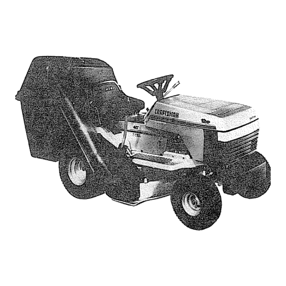
12 HP.
LECTRIC
40" MOWER
SPEED
LAWN TRACTOR
START
® Assembly
o Operation
e Maintenance
e Service
and Adjustment
® Repair Parts
F-91726
12-01-90
Sears, Roebuck and Co, Chicago, IL 60684
UoS.A.
Printed i nUSA
Advertisement
Table of Contents

Related Manuals for Craftsman 502.255193


Summary of Contents for Craftsman 502.255193
- Page 1 o_vne Model 502.255193 , ,i i iil,ii START 12 HP. LECTRIC 40" MOWER SPEED CAUTION: LAWN TRACTOR Read And Follow All Safety Rules And Instructions Before ® Assembly Operating This o Operation Equipment. e Maintenance e Service and Adjustment ® Repair Parts F-91726 12-01-90 Sears, Roebuck and Co, Chicago, IL 60684...
- Page 2 SAFETY RULES Safe Operation Practices for Riding Vehicles As Recommended by American National Standards Institute This cutting machine is capable of amputating hands and feet and throwing objects. Failure to observe the following safety instructions could result in serious injury or death to the operator or bystanders.
- Page 3 SAFETY RULES - continued SLOPE OPERATION: Slopes and rough terrain are major factors related to loss of control and tip over accidents which can result in severe injury or death. All slopes require extra caution. If you cannot back up the slope or if you feet uneasy on the slope, do not mow ito See the "Slope Guide"...
- Page 4 PRODUCT SPECIFICATIONS Congratulations on your purchase of a Sears Tractor. It has been designed, engineered and manufactured to give you the best poss- Briggs & Stratton Engine 12 HP,. ible dependability and performance. Charging System 3 amperes at 3600 rpmr. If you experience any problem you cannot...
-
Page 5: Table Of Contents
TABLE OF CONTENTS MAINTENANCE .......... 27-34 SAFETY RULES ..........SERVICE AND ADJUSTMENT ...... 35-41 CUSTOMER RESPONSIBILITIES ......STORAGE ............PRODUCT SPECIFICATIONS ....... TROUBLE SHOOTING CHART ......WARRANTY ............ELECTRICAL SCHEMATIC ........ TABLE OF CONTENTS ........REPAIR PARTS, MOWER ......44-57 INDEX ............... - Page 6 That to the Usefulness of Your Craftsman Lawn Tractor Sears offers a wide variety of attachments that fit your iawn tractor Many of these are listed below with brief explanations of how they can help you°This list was current at the time of publication; however, it may change in future years- more attachments may be added, changes...
- Page 7 ASSEMBLY i ,,,,,,, ,u ,,,,,,,,, i,,, ...., , i ,,,,,,,,,,,,,, ,, ,,, ,,, PREPARATION Before being put in the carton, the unit was carefu[iy inspected carton made to protect the unit during shipment, The unit is comptetety assembled except for the items shown this page These items...
- Page 8 ASSEMBLY TO PREPARE Remove and discard CHARGE THE BATTERY NOTE; Before you install the battery, add the battery acid the meta_ (Electrolyte) and charge the battery° Battery acid will damage paint and parts, Vent Cap WARNING: Read the instructions included with the battery acid container.
- Page 9 ASSEMBLY _OW TO ASSEMBLE rilE STEERRNG WHEEL Jse the fasteners shown below to install the steering wheeE The ;asteners are shown at full size S1eedng Wheel ix66 t 5×90 Bellows Make sure the front wheels point forward. Slide the bellows over the steering post.
- Page 10 = == =l= H =l=l,====,l,l,l,l,l==l,l=ll=l=== ASSEMBLY = 111i= iH ,lliHi,i,ll CHECK THE DRIVE BRAKE TO ATTACH THE HUB CAPS Push each hub cap onto the center' hub of each wheel, Make sure The drive brake can be easily checked as foHows_ Set the parking brake Move the shift lever to the neutral (N) position Push the unit.
- Page 11 iMPORTANT: Remove and identify the contents of each box as shown below: CONTENTS OF BOX Containers Weight Bracket Hin_ Frame Mount Bracket _L=_ CONTENTS OF BOX Window Parts Bag (In paper bag_ Extension Tube and Plate Assembly Fr°ntWi_" (2) Plastic Bags (Not shown) Channel Elbow...
- Page 12 PARTS BAG - conterlts for Grass Bagger The fasteners and other loose parts are shown below. The fasteners are shown full size with the quantities in brackets (). NOTE: Some of the fasteners will not be required for your modoLi_., ..,..
- Page 13 ASSEMBLY TO ASSEMBLE THE FRONT WEIGHT Assemble the front weight support with the fasteners shown full size below, © Weight Support 2x74 15x88 15x 109 Assemble the four carriage bolts (A) and four jam nuts (B) to the tractor as shown,, Make sure jam nuts (B) are tight°...
- Page 14 iiiiiii1,,111 ASSEMBLY H =l= =H,N :::::::::::::::::::::::::::::::: TO MOUNT THE FRAME ASSEMBLY Remove and discard the two self=tapping screws from the rear of the framer Use these two holes to mount frame bracket_ Frame Bracket Attach the bottom of the frame bracket to the frame with hex bolt (A} and Iocknut (B) Do not tighten at this t_me= lx125 0-8t19...
- Page 15 From the right side of the unit, install the channel pin throug h the channel as shown, Rotate the channel pin to lock the channe_ in place, Mount the outer tube to the channel as shown, Make sure the holes on one end of the outer tube are on the right side of the unit, Use the fasteners shown full size below...
- Page 16 IIIHII=I=IIIll i= i ASSEMBLY TO MOUNT THE COVER Assemble the hinge to the cover with the fasteners shown full size below,. Push tire hinge toward the top of the cover,, Make sure the screws are at the bottom of the holes in the hinge,, Tighten the fasteners.
- Page 17 ........ i,, ,lui un,llll i ,l_Jii ASSEMBLY TO MOUNT THE EXTENSION TUBE Assembfe latch pin (A) to the extension tube with fasteners shown below 54563 15x89 2x39 Move the lift lever to the highest cut position, Disconnect the wire to the spark plug.
- Page 18 ASSEMBLY TO MOUNT THE CONNECTOR TUBE Mount the connector tube with the fasteners shown full size Assemble the handle and the rubber latch to the connector' below,, tube with the fasteners as shown,_ Hoid the screws with screwdriver and tighten the Iocknuts, Atign the hole in the connector...
- Page 19 ASSEMBLY TO ASSEMBLE THE CONTAINERS NOTE: There is only one way that these containers can be put together. Carefully read and follow the instructions below_, BOTTOM PIECES Separate the six container pieces into two groups You will have 2 tops, 2 middle and 2 bottoms pieces as shown,...
- Page 20 ASSEMBLY lllll illll TO ATTACH THE CONTAINERS Tilt the seat forward Hold the handle on the back of the cover,, Pull back on the handle and lift to raise the cover plastic bag linings, not shown in the illustration, included with the grass bagger The plastic...
-
Page 21: Blade Engagement Control
OPERATION KNOW THE PRODUCT Before you operate the unit, read this instruction book° If you understand the unit and how the unit operates, you will get the best performance. When you read this instruction book, compare the illustrations to the unit. Learn the location of the controls. To help prevent an accident, follow the operating... - Page 22 OPERATBON The operation of any lawn mower can result foreign objects thrown in the eyes, which result in severe damage° Always wear tShlftLever safety glasses or eye shields before starting your lawn mower while mowing. recommend Wide Vision Safety Mask over the spectacles or standard safety...
- Page 23 OPEBATnON TO USE THE THROTTLE CONTROL TO OPERATE WITH THE MOWER HOUSING Use the throttle control to increase or decrease the speed of tile engine_ WARNING: The deflector is a safety device,, Do To start a cold engine, move the lever to the START or not remove the deflector°...
- Page 24 HOW TO USE THE GRASS BAGGER WARNING: Do not ride up or down slopes that are too steep to back straight up. Never tide the unit across a slope.. See the "Slope Guide" in the back of this book for information on how to check slopes..
-
Page 25: Carburetor
OPERATRON BEFORE STARTING THE ENGINE TO START THE ENGINE WARNING: electrical system CHECK OIL - Add as needed operator presence system that includes a sensor switch mounted in the seat. These components NOTE; Do not check level of the oil while engine tell the electrical system if the operator is sitting runs. -
Page 26: Install
OPERATION OPERATING TIPS Check the blade engagement control for correct adjustment. Before you make an inspection, adjustment (except for the For the blade(s) to disengage correctly, the adjustment must carburetor) or repair, make sure the wire from the spark plug be correct is disconnected_ Before you use the unit, check the oil in the engine and add oil... -
Page 27: Storage
MAINTENANCE SCHEDULE FIRST EVERY EVERY EVERY PROCEDURE EACH BEFORE STORAGE HOURS HOURS HOURS HOURS STORAGE DATES Blade, Inspect & Sharpen B!ade Engagement Control, Check Brake, Check Clutch, Check Lever, Shift Check Tires, Check ..Battery, Check & Char_3e _ Battery, Ctean Lubrication Oil, Check Coolin 9 System,... - Page 28 MAINTENANCE _NSPECT BLADE WARNING: Before inspect or remove blade, disconnect the wire to the spark plug, the blade hits an object, stop the engine° Check the unit for damage The blade has sharp edges,. When hold blade, use gloves or cloth material to protect your...
- Page 29 MAUNTENANCE HOW TO CHECK ADJUST THE BLADE ENGAGEMENT CONTROL Completely WARNING: prevent an injury, blade engagement control must operate correctly.. Engaged Position Stop the engine.. Disconnect the wire from the spark pEug.. Before you adjust the blade engagement control lever, check level mower housing.
- Page 30 MAnNTENANCE TO CHECK ADJUST THE DRIVE BRAKE Completely push the clutch/brake pedal forward,, Set the parking brake Movethe shlfttevertotheneutral(N)position, Push the unlt. If the rear wheels rotate, adjust or replace the brake pads Adjust Brake Arm the drive brake as follows location tile brake...
- Page 31 5AAtNTENANCE TO ADJUST THE SHOFT LEVER Shift Cover NOTE: To help show the shif_ gate, the shift cover was removed in the illustration, Shift Lever Move the shift lever to the NEUTRAL position Carefufly pull the shift cover away so that you can see the shift gate Carefully push the shift lever towards the seat until you feel...
- Page 32 MAINTENANCE _JL_L_ BATTERY CUT AWAY VIEW Vent To charge or clean the battery, remove the battery from the unit as follows Correct WARNING: To prevent sparks, disconnect the Liquid black battery cable from negative (--) Level terminal before you disconnect the red cable.. WARNING: The battery contains sulphuric acid which is harmful to the skin, eyes and clothing.
- Page 33 MAINTENANCE i ii Hi ,ll ill lllil liiNil IENGONE TO CHECK THE OIL NOTE: Do not check the le;vel of the oil while the engine runs. Make sure the unit is level. Clean the area around the dipstick, Remove the dipstick_ Wipe the oil from the dipstick°...
- Page 34 MAgNTENANCE ,=,,,J, iLiJ ,,, H ii TO CLEAN THE AIR FILTERS Some engines have two filters, an outer foam filter around an inner paper filter. Clean the air filters every 50 hours. If you operate dirty conditions, service more often NOTE: Never run the engine with the air filters re moved_ The a ir filters will help protect the engine against wear°...
- Page 35 TO ADJUST THE CARBURETOR The factory settings for the carburetor are for most conditions, the engine is operated under the following conditions, you can adjust the carburetor mixture. The engine has a loss of power or does not run smooth. A change from summer...
- Page 36 SERVICE AND ADJUSTMENT .,I,,,,,,,,,UUl1' J =l, n TO REMOVE THE MOWER HOUSING Attach the front hanger to the axle support with the hanger rod. Fasten with the fasteners as shown. See illustration "F" beEow,. Move the lift lever to the lowest position, Make sure the mower drive belt is between...
- Page 37 SERVICE AND ADJUSTMENT TO REPLACE MOWER DRIVE BELT Remove the mower housing, See the instructions on "How Put the belt around the left mandrel putley To Remove The Mower Housing'L Make sure the "V" side of the mower drive belt is against Pull the belt retainer away from the idler pulley and remove...
- Page 38 SERVICE AND ADJUSTMENT REPLACE THE MOTION DRRVE BELT Motion 1 • Remove the mower housing, See the instructions on "How To Remove The Mower Housing" in this instruction book Completely push pedal forward engage Drive Pulte, parking brake, Loosen The" Remove the idler pulley Belt Guides...
- Page 39 SERVICE AND ADJUSTMENT TO LEVEL THE MOWER HOUSaNG If the mower housing is level, the blade wilt cut easier and the lawn will look better. WARNING: Before make an inspection, adjustment, or repair to the unit, disconnect wlre to the spark plug_ Remove the spark plug...
- Page 40 SERVnCE AND ADJUSTMENT TO REPLACE THE LIGHT BULB Raise the tractor hood, Pull the tight socket from the bezel. Pull the light bulb from the socket Install a new light bulb Push the socket into the bezel. TO CLEAN THE MOWER HOUSING stop the engine and disconnect the wire to the WARNING: Before you clean the mower housing.
- Page 41 SERVICE AND ADJUSTMENT TO START WITH A WEAK BATTERY TO REPLACE THE FUSE If the fuse is blown, the engine will not start, The location of the fuse Ifthe batter,/is too weak to start the engine, the battery needs to be is next to the battery.
- Page 42 TROUBLE SHOOTING CHART (Recoil-Start Electric Models) PROBLEM: The engine will not start. PROBLEM: A hot engine causes a decrease in power° Clean the air screen Follow the steps, How To Start The Engine in this book. Check the oil Clean the battery terminals Tighten...
-
Page 43: Electrical Schematic
MODEL 502.255193 ELECTRICAL SCHEMATIC BATTERY BLACK SOLENOID STARTER FUSE 15 AMP BLACK SEAT SWITCH (SEAT UNOCCUPIED ATTACHMENT CLUTCH PEDAL IGNITION INTERLOCK SWITCH INTERLOCK SWITCH BLAcK(CLUTCHo_ENGAGED)o BLACK (DISENGAGED)!_,r - _ -_ BLK. BLK. YELLOW ;L__O_4YELLOW _ ,_ YLW. N'C i"_0N N EC-_--R (CLOSED IF UNPLUGGED SPARK... - Page 44 MODEL 502.255193 REPAIR PARTS CHASStS & HOOD D-5736 F-91726...
- Page 45 REPAIR PARTS MODEL 502.255193 CHASSIS & HOOD PART MFG. PART DESCRIPTION DESCRIPTION 91779E60t 56542 Panel, Left Seat 91778E601 91963Z Panel, Right Plate Assembly, Switch 92013 164x25 Clip, CabIe Spring, Compression 91858E601 91964 Dash Assembly Spring, Seat 91759 91822 Bearing Glide, Spring 38 Cable 92087 9x38...
- Page 46 MODEL 502.255193 REPAIR PARTS MOTION DRmVE I_5701 5 58 •14 17 F-91726...
- Page 47 REPAaR PARTS MODEL 502.255393 _,qOTnON DRDVE PART IVlFG. PART rvlFG, DESCRIPTION DESCRIPTION Grip 92055 Rod, Clutch 91808Z Grip, Inner 20476 Washer 17x148 Handle, Shift 9203tZ Yoke, Shift 92041Z Bolt, Shoulder 9x39 Bolt, Hex lx82 Pin, Cotter STD560907 30x20 Lockwasher STD551125 t8x32 Washer STD55t031...
- Page 48 MODEL 502.255193 REPAIR PARTS STEERING D-5699-3 F=91726...
- Page 49 REPAmR PARTS MODEL 502.255193 STEERaNG PART MFG. DESCRIPTION Wheel, Steering 92077 15x90 Nut, Hex STD541531 lx66 Bolt, Hex STD623115 Shaft, Steering 91860Z lx74 Bolt, Hex STD623112 Screw 26x249 Bracket, Sector 91716E700 Gear, Pinion 402075 Bearing 9t756 t x84 Bolt, Hex ** STD523110 15x87 Locknut,...
- Page 50 MODEL 502.255193 REPAIR PARTS MOWER SUSPENSION D-5698 F-91726...
- Page 51 REPAIR PARTS MODEL 502.255193 MOWER SUSPENSION PART iViFG. NO. DESCRIPTION 92055 Grip 91781Z Lever, Blade Control 25x3 Bolt, Hex STD541425 15x67 Locknut, Hex 91917E700 Lever Assembly, Switch STD533107 2x53 Bolt, Carriage 166x32 Spring, Torsion 92066E700 Bracket, Left Rear Hanger 15x79 STD54t031 Nut, Flange 92131...
- Page 52 MODEL 502.255193 REPAIR PARTS MOWER HOUSING D,-5697-t 12 / 3 37 F-91726...
- Page 53 REPAIR PARTS MODEL 502.255193 MOWER HOUSING iVIFG, PART NIFG. PART NO. DESCRIPTION NO. DESCRIPTION 9t797E700 Guide, Belt 15xlO1 Nut, Hex 91813E700 Bracket Assy.,o Left Lifter 18x33 LOckwasher 165x72 91943 Spring, Extension Pulley, Jackshaft 91743E700 15x84 Bracket, Pivot STD541437 Locknut, Flange 91770E700 Plate 91903...
- Page 54 REPAIR PARTS MODEL 502.255193 WiRiNG D-5749 N3_19 M07731 M3V7'8 I" F-91726...
- Page 55 REPAIR PARTS MODEL 502.255193 WIRING 03 _.0 03 03 t._J "r F-9!726...
- Page 56 REPAIR PARTS _ODEL NO. 502.255193 ENGINE MOUNT F-91726...
- Page 57 MODEL 502.255193 REPAIR PARTS ENGINE MOUNT PART NIFG. DESCRIPTION Fuel Cap 55988 Fuel Tank 91869 Hose Clamp 91174 Fuel Line 92160 Hose Clamp 23713 Screw 26x214 Screw STD610803 26x201 Throttle Control 91983 Engine Briggs & Stratton 92099PA Model: 281707-O428-01 Bolt, Hex lx134 Shield, Muffler Heat...
- Page 58 REPAIR PARTS MODEL 502.255193 GRASS BAGGER D-8t76 25 2 F-91726...
- Page 59 MODEL 502.255193 REPAIR PARTS GRASS BAGGER PART MFG. NO. DESCRIPTION 193xl Fastener (Included with key noo 2) Containers (Quantity of 2 included) 54727SE Window Clip 54571Z STD5414t0 Locknut, 15x8 t Handle, Plastic 54537 Screw STD511007 4x21 Cover 91968 Screw 26x246 Window 54557 Nut, Expansion...
- Page 60 REPAIR PARTS 502.255193 MODEL SiX SPEED TRANSAXLE _.PEERLESS MODEL 930-011 _970 F-91726...
- Page 61 MODEL 502.255193 REPAIR PARTS SIX SPEED TRANSAXLE PEERLESS MODEL 930-011 PART PART DESCRIPTION DESCRIPTION 772108 Cover, Transaxle Lever, Brake 790060 780086 792073 Bearing, Needle Screw, Flanged Hex hd.. ¼-2Oxl 770102 Case, Transaxle Nut, Lock 5/16-24 792075 776260 Shaft, Counter Holder, Brake Pad 790025 776219 Shaft Pinion Assembly, Output...
- Page 62 ENGINE PARTS iLLUSTRATION 12 HP. BRIGGS & STRA'R'ON - MODEL 281707-O428-O1 _ _353 _)354 66,3 _1564 ,___._62 634A ]1019 l ABEl. K ITI 1021 1020 [___58 GAs_ETI *SPECIAL TOOLS REQUIRED SEE REPAIR INSTRUCTION TO INSTALL,. MANUAL Assemblies include all parts shown in frames F-91726...
- Page 63 ENGINE PARTS ILLUSTRATION 12 HP. BRIGGS & STRATTON - MODEL 281707-0428-01 121 CARBURETOR OVERHAUL Assemblies include all parts shown in frames F_91726...
- Page 64 ENGINE PARTS iLLUSTRATiON 12 HP. BRIGGS & STRATTON - MODEL 281707-0428-01 Housing Length --_ _=== O__ NOTE: To identify Briggs & Stratton manufactured starter motors, measure the housing length,. Assemblies include all parts shown in frames. F-91726...
- Page 65 ENGINE PARTS LIST 12 HP. BRIGGS & STRATFON - MODEL 281707-0428-01 MFG. MFG. PART PART DESCRIPTION DESCRIPTION 490450 92909 Cylinder Assembly Screw -Connecting Valve -Exhaust 399265 262246 Bearing, Cylinder Valve -Intake 262247 NOTE: Requires special tools for instatlation_ 65906 Spring -Intake Valve Seal -Oil...
-
Page 66: Starting
ENGINE PARTS LIST 12 HP. BRIGGS & STRATTON - MODEL 281707-0428-01 IV1FG. MFG. PART PART DESCRIPTION DESCRIPTION 390837 Armature Assembly Oil Slinger, Gov. Gear & Bkt. 490815 Washer -Air Cleaner 94249 Plate -Governor Control 491594 231597 Screw -Air Cleaner Sere 94018 Bushing -Governor... - Page 67 "4 , ; : F-91726...
-
Page 68: Spark Plug
® 2 HP. ELECTRIC START 40" MOWER 6 SPEED LAWN TRACTOR The Model Number for the mower is found on a decal attached to the back of the frame. The Model Number for the engine is found on the blower housing above the spark plug.
Need help?
Do you have a question about the 502.255193 and is the answer not in the manual?
Questions and answers