Sign In
Upload
Manuals
Brands
Campbell Manuals
Weather Station
CM10
Campbell CM10 Manuals
Manuals and User Guides for Campbell CM10. We have
1
Campbell CM10 manual available for free PDF download: Instruction Manual
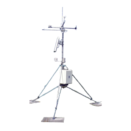
Campbell CM10 Instruction Manual (68 pages)
Tripod Weather Station
Brand:
Campbell
| Category:
Weather Station
| Size: 5.51 MB
Table of Contents
Table of Contents
3
1 Preparation and Siting
7
Installation Tasks
7
Indoors
7
Outdoors
7
Tools Required
8
Tools for Tripod Installation
8
Tools for Instrumentation and Maintenance
8
Supplies for Power and Communications Options
9
Siting and Exposure
9
Wind Speed and Direction
9
Temperature and Relative Humidity
9
Precipitation
10
Solar Radiation
10
Soil Temperature
10
Effect of Structure on Wind Flow
11
2 CM6/CM10 Tripod Installation
13
CM10 Weather Station
13
Specifications
14
CM6 Heights and Leg Diameters
14
CM10 Heights and Leg Diameters
14
Tripod Parts
15
Tripod Installation
15
Extending the Tripod Legs
16
Tripod Grounding
17
Tripod and Component Orientation
17
Ground Rod and Clamp
18
CM10 Guy Kit Installation
19
Tripod Ground Connections
19
CM10 Guy Kit Parts
19
Guy Wire Installation
20
Thimble Twisting
20
Turnbuckle Assembly
21
Sensor Mounting Brackets
22
019ALU Crossarm Sensor Mount
22
CM202, CM204, CM206 Crossarms
22
CM210 Crossarm-To-Pole Bracket (Top) Is Included with the Crossarm for Attaching the Crossarm to the Tripod's Mast
22
Crossarm Mounting
22
CM225 Pyranometer Stand
23
Gill Radiation Shields (41303-5A, 41003-5, 41005-5)
23
ALU Crossarm and Lightning Rod
23
CM225 Solar Radiation Mount with a LI2003S Leveling Base and LI200X Solar Radiation Sensor
24
CM225 Attached to a Mast
24
3 Instrumentation Installation
25
Enclosure, Datalogger, Power Supply
25
Enclosure
25
An Enclosure with the "-MM" Mounting Option Attaches to a Tripod Mast Via U-Bolts
26
This Exploded View Shows the Components of a "-MM" Bracket
26
Datalogger and Power Supply
27
BPALK Alkaline Power Supply
27
An Enclosure Attached to a Tripod Mast
27
PS100 Rechargeable Power Supply
28
Solar Panel
28
CR1000 and PS100 Mounted to an Enclosure Backplate
29
SP10 Solar Panel
29
Sensor Connection
30
Routing and Wiring Sensor Leads to the Datalogger
30
Communication and Data Storage Peripherals
31
CFM100, NL115, or NL120
31
COM220 Phone Modems
31
The NL115 Connects to the Cr1000'S Peripheral Port Allowing Data to be Stored on Removable Compact Flash Cards
31
Cellular Transceivers
32
COM220 Modem with Surge Protector
32
SRM-5A Rad Modem and SC932A Interface
33
SRM-5A at the Computer
33
SRM-5A at the Datalogger
33
SRM-5A Rad Modem and SC932A Interface
34
SRM-5A Wiring
35
RF500M RF Modem and RF310-Series Transceivers
36
RF500M Modem Configuration
36
RF500M RF Base Station
37
Install Nearest Repeater/Field Station
38
MD485 Multidrop Interface
38
MD485 Multidrop Interface at the Datalogger
38
MD485 Multidrop Interface at the Computer
39
Sealing and Desiccating the Enclosure
39
You Can Configure any Two Types of Interface Ports (RS-485 RS-232, and CS I/O) to be Used at a Time
39
Enclosure Supply Kit
40
4 Sensor Installation
41
034B Met One Windset
41
Met One 034B Wind Speed and Direction Sensor
41
And 05305 RM Young Wind Monitors
42
RM Young Wind Monitor
42
03002 RM Young Wind Sentry Wind Set
43
03002 Mounted to the Mast
43
03002 Mounted to CM202, CM204, or CM206 Crossarm
43
Mounted to a CM200-Series Crossarm
43
Licor Silicon Radiation Sensors (LI200X, LI200S, LI190SB)
44
107/108 Temperature Probe
44
LI200X/LI200S/LI190SB and LI2003S Leveling Fixture
44
Temperature Probe
45
107/108 Soil Temperature Probe
46
HMP50 Vaisala Temperature and RH Probe
46
HMP50 Temperature and RH Probe
47
HMP45C/HMP35C Vaisala Temperature and RH Probe
48
HMP45C Vaisala Temperature and RH Probe
48
CS100 or CS106 Barometric Pressure Sensor
49
Texas Electronics Tipping Bucket Rain Gages (TE525, TE525WS, TE525MM)
49
TE525 Texas Electronics Rain Gage
49
TB4, TB4MM or CS700 Rain Gage
50
SR50A Sonic Ranging Sensor
51
Beam Angle
51
Mounting Height
51
Beam Angle Clearance
51
Reference Point
52
Mounting Options
52
Distance from Edge of Transducer Housing to Grill
52
SR50A Mounted to a Crossarm Via the 19517 Mounting Kit
53
The SR50A Mounted to the Crossarm Shown from Another Angle
53
CS616 Water Content Reflectometer
54
237 Leaf Wetness Sensor
55
Insertion Guide
55
257 Soil Moisture Sensor
56
CS210 Enclosure Humidity Sensor
57
Wind Direction Sensor Orientation
57
Determining True North and Sensor Orientation
57
National Geophysical Data Center Web Site
58
Magnetic Declination for the Contiguous United States
58
Declination Angles East of True North Are Subtracted from 0 to Get True North
59
Declination Angles West of True North Are Added to 0 to Get True North
59
5 Standard Software Installation
61
Datalogger Program
61
Weather Station or Datalogger Support Suite
61
Quick Start Review
61
6 Maintenance and Troubleshooting
63
Maintenance
63
Instrumentation Maintenance
63
Batteries
63
Desiccant
64
Sensor Maintenance
64
Troubleshooting
65
No Response Using the Keypad
65
No Response from Datalogger through SC32B or Modem Peripheral
65
Nan Displayed in a Variable
66
Unreasonable Results Displayed in a Variable
66
Advertisement
Advertisement
Related Products
Campbell CM6
Campbell CM10K
Campbell CM110
Campbell CM115
Campbell CM120
Campbell CM106
Campbell CM106K
Campbell CM106B
Campbell CM106BE
Campbell CM106BK
Campbell Categories
Measuring Instruments
Accessories
Modem
Weather Station
Recording Equipment
More Campbell Manuals
Login
Sign In
OR
Sign in with Facebook
Sign in with Google
Upload manual
Upload from disk
Upload from URL