Table of Contents
Advertisement
Available languages
Available languages
Advertisement
Table of Contents

Related Manuals for Craftsman 351.233780


Summary of Contents for Craftsman 351.233780
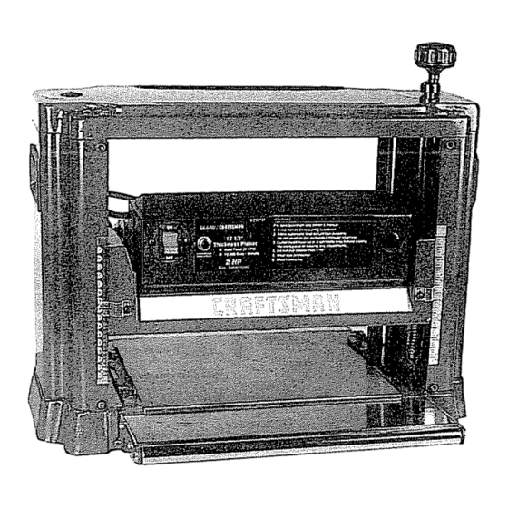
- Page 1 NlanuaH OperatoF's ® 12½" PLANER Model No. 351.233780 CAUTION: Read and follow all Safety Rules and Operating Instructions before First Use _f this Product. .3ears, Roebuck and Co., Hoffman Estates, IL 60179 U.S.A. _629.00 Draft (07/28/97)
- Page 2 121/2" PLANER TOOL SHOULD BE MAINTAINED If this Craftsman Planer fails due to a defect in material or workmanship within one year from the date of pur- ° Always unplug tool prior to inspection chase, contact the nearest Sears in-home major brand...
- Page 3 INSTALL BLADE GUARD • Use recommended accessories (refer to page 15), Use of improper accessories may cause risk of Refer to Figure 8, page 14. injury to persons. WARNING: To properly guard against accidental con- Handle workpiece correctly,, Protect hands from pos- tact with cutterhead, blade guard must be fastened sible injury, securely...
- Page 4 WARNING: Do not permit fingers to touch the termi- nals of plug when installing or removing from outlet. = Plug must be plugged into matching outlet that is properly installed and grounded in accordance with all Jocal codes and ordinances. Do not modify plug provided If it will not fit in outlet, have proper outlet installed by a qualified electrician,...
- Page 5 MOTOR developed) motor with overload protection Motor has on/oft switch with removable key to prevent accidental Planer is Supplied with a 2 HP motor installed, start-up Unit features double-edged blades for mini- The 120 Volt AC universal motor has the following mized downtime, top mounted rollers for workpiece specifications: return, built-in carrying handles for portability, and fold-...
- Page 6 DEPTH OF CUT o Slowly rotate handle (Fig, 8, No. 1) to raise or lower the cutterhead. Rotate clockwise to raise roUercase, Thickness planing refers to the sizing of lumber to a counterclockwise to lower rollercase Rollercase wilt desired thickness while creating a level surface parallel be moved by _004"...
- Page 7 FEEDING WORK • Position knife gauge assembly on the cutterhead so that the two knife gauges (Fig 8, No t6) are approxi- Refer to Figures 8 and 9, pages 14 and 16, mately at the same distance from the cutterhead edge. WARNING: Always turn the planer off and disconnect o Hold knife gauge assembly against cutterhead so...
- Page 8 CLEANING KNIVES • To avoid snipe, gently push the board up while feed- ing the work until the outfeed roller starts advancing Gum and pitch will collect on blades and cause excess it.. friction when working. Blades will overheat and wear o Move to the rear and receive planed board by gently out at accelerated rate.
- Page 9 LUBRICATION ,, Motor and cutterhead bearings are sealed and need no lubrication. • Beveled gears and elevation screws should be cleaned of debris and greased. • The base cover can be coated with a lubricant such as furniture wax, to make the workpiece feed smoother.
- Page 10 CORRECTIVE ACTION SYMPTOM......POSSIBLE CAI0,SE(S) ' ....1,Duii blades 1 Reverse, replace or sharpen blades per Snipe instructions, See "Adjusting Blade Height" (gouging at ends of board) and "Maintenance" i 2Support long boards. 2,Inadequate support of long boards 3Uneven force on cutterhead 3 Gently push board when board is in contact with only one feed roller, See "Feeding Work_' &Check position on elevation screws,,...
- Page 11 SYMPTOM POSSIBLE CAUSE(S) CORRECTIVE ACTION Planerwiltnot operate 1•No power to p_aner 1°Check power source by qualified electrician, 2,Turn planer off, Reset motor overload 2Motor overload protection tripped protection, See "Overload Reset°" 3. Defective or loose switch or wiring 3,Check switch and wiring by qualified electrician.
- Page 12 "0...
- Page 13 "o c 0_ :nO £ _°o li90 O 0 0 o q q q q,q q q q C) 0 C) Oi _mmmu_mm_ __0_ ed C4 ¢-4e,l¢14e9 O0 cO CO "If,', 09 o o_CO _ 0o _°x &0 fl P0 €.a o m m C919 _gg_ oooog...
- Page 14 Model 351.233780 Figure 8 - Replacement Parts Illustration for Roliercase Knife Gauge Assembly ..
- Page 15 PART NO. PART NO, DESCRIPTION QTY, DESCRIPTION QTY. 963&00 Handle STD315225 6202LL Bearing* ..1760,00 6-1 0 x 16mm Socket 1441o00 3BMI-34 Retaining Ring Head Bolt 3850,00 Indicator STD852006 6mm Lock Washer* 9641,00 Wire Clip 9631,00 0533.00 Plug 3AM1-15 Retaining Ring 8-1o25 x 16ram Sockei Pan 1218,00 3843,00...
- Page 16 Model 351.233780 Figure 9 - Replacement Parts Illustration for Base...
- Page 17 PART NO. DESCRIPTION QTY. , PART NO. DESCRIPTION 9644.00 Elevation Screw (Lel 6-1.0 x 10mm Pan 3812.,00 964&00 Head Screw Elevation Screw (Right) 9646.00 Gear 965400 Guide Plate 7383.00 9655.00 Column 3CMI-9 E-Ring 3873O0 5331.00 5-0.8 x 12mm Socket 4 x 4 x 8mm Key 5mm Flat Washer* Head Bolt STD851005...
- Page 18 PARA • Consutte el manual para informa_sesobre los procedimientos LA CEPILLADORA DE 31,8 CM CRAFTSMAN de mantenimiento y ajuste especificos Si la cepitladoraCraftsman faila debido a un defecto on el materi- • Mantenga ta herramienta lubricada y limpia, para obtener una al o en la mane de obra, dentro de un afio a partir de la fecha de operaci6n m_s segura.
- Page 19 ° Nunca se pare en la herramienta Se pueden producir lesiones graves si la herramienta se inctina, o si se entra en contacto con la hoja por accidente. Refi_,rase alas Figuras 8 y 9, p&ginas 14 y 16 Cenozca su herramienta Aprenda la operaci6n de la herra- mienta, aplicaci6n y limilaciones especificas.
- Page 20 Taladre los agujeros pitoto en la superficie para montar con los pemos de entibamiento (Fig. 9, No. 29). Tomacorriente conectado ° Monte la cepilladora en la superficie de trabajo apern,-_ndolaa a tierra correctamente tray,s de los agujeros Punta de conexi6n a tierra Enchufe de 3 puntas Figura 3 - Receptdcuto de 3 Puntas...
- Page 21 Si et interrupter se dispara, apague la cepilladora y vuelva a Muchos de los torniltos de la plancha de cubierta, las tube- ajustar el circuito presionando el bot0n, rias de agua y las cajas de tomacorriente no est,_n conecta- dos a tierra correctamente Para asegurar una conexi6n a tie-...
- Page 22 AJUSTE DE LA PROFUNDIDAD DEL CORTE No fuerce el corte_ Si funciona mas despacio o se para, el motor se calentar& demasiado Pe_mita que la alimentaciSn Refi6rase a Ias Figuras 8 y 9, paginas t4 y 16 automf_tica funcione correctamente El espesor de la table que ia cepilladora va a prodL_cirqueda indi- °...
- Page 23 Asegurese que ambos pernos hexagonales sujeten la posi- PRECAUCION: Todo articulo que se encuentre con las hojas ci6n de laplaca del rodiflo Sujete el perno hexagonal con una de la cepiltadora puede set lanzando con fuerze creando un ries- Itave de boca y asegure e] ajuste apretando la tuerca go de lesiones, Reviseel alineamiento del rodillo de soporte en cada extreme PREPARACION...
- Page 24 o Lacepilladora cuenla c onrodiitos dei'etorno (Fig8,No12) • Suefte todos los pernos de seguridad (No 22) (g_relos en el sentido de las manillas del reloj) usando una liave de boca. en fa Parte superior, de mode qua et ayudante puede pasade el trabjo de vuella ai operador Remueva e invierta la hoja AVISO: El ayudante fiene que tomar ]as mismas precauciones...
- Page 25 Suelle y remueva cuatro tornillos de cabeza hueca (Fig..9, CANAL DE ASTILLAS DEL COLECTOR DE POLVO No. 32) en la cubierta derecha (Fig. 9, No..31) Remueva la Refi_rase a la Figura 8, p_gina 14. cubierta. El canal de astitlas del cotector de polvo (no se muestra) est_ °...
- Page 26 MEDIDAS CORRECTiVAS SINTOMA CAUSA(S) POSIBLE(S) Hojas desafiladas lnvi_rtalas, €_mbieias o afilelas segt3n las instrucciones. Redondeo (depresiones en los extremes de la Vea "Ajuste de ta A[tura de la Hoja" y "Mantenimiento" tab]a) 2. Soporte inadecuado de tas tablas,largas Soporte ]as tab]as largas Fuerza dispareja en el portacuchi]la Suavemente empuje la tabla cuando...
- Page 27 IVlEDIDAS CORRECTIVAS ..SlNT,0MA ....CA,USA(S),,,P,0SIBLE(S) ....La cepiiladorano opera I.. No tienela energia conectada Un electricista calificado tiene que revisar la fuente de fa energia 2 Apague la cepiJladora Vuefva a ajustar fa proteccidn La protecciSn contra la sobrecarga contra la sobrecarga de! motor Vea "Reajuste de motor se dispar6 Sobrecarga"...
- Page 28 For the repair or replacement parts you need delivered directly to your home Call 7 am - 7 pm, 7 days a week 1oS00=366-PART (1-800-366-7278) Para ordenar piezas con entrega domicillo- 1-800-659-7084 For in-home major brand repair service Call 24 hours a day, 7 days a week 1-800-4-REPAIR (1-800-473-7247) Para pedir servicio...
Need help?
Do you have a question about the 351.233780 and is the answer not in the manual?
Questions and answers