Table of Contents
Advertisement
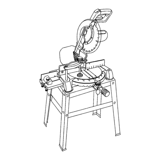
Operator's Manual
CRRFTSMRN °
3 HP (Max. Developed)
10" Blade
4800 R.P.M.
MULTI-MITER TM
COMPOUND
MITER SAW
Model No.
137.242760
CAUTION:
Before using this Miter Saw,
read this manual and follow
all its Safety Rules and
Operating Instructions
Customer Help Line
1-800-843-1682
• Safety Instructions
•
Installation
•
Operation
•
Maintenance
•
Parts List
Sears, Roebuck and Co., Hoffman Estates, IL 60179 U.S.A.
Visit our Craftsman webslte: www.sears.comlcraftsman
PaN No. 137242760001
Advertisement
Table of Contents

Related Manuals for Craftsman MULTI-MITER 137.242760


Summary of Contents for Craftsman MULTI-MITER 137.242760
- Page 1 • Operation read this manual and follow • Maintenance all its Safety Rules and • Parts List Operating Instructions Customer Help Line 1-800-843-1682 Sears, Roebuck and Co., Hoffman Estates, IL 60179 U.S.A. Visit our Craftsman webslte: www.sears.comlcraftsman PaN No. 137242760001...
- Page 2 SECTION PAGE SECTION PAGE Know Your Miter Saw ..Warranty ........Product Specifications ....... Glossary of Terms ......Power Tool Safety ......Assembly and Adjustments....Operation........Compound Miter Saw Safety ....Maintenance ........Electrical Requirements and Safety ..Accassodes and Attachments ....Troubleshooting Guide.......
- Page 3 12.ALWAYS WEAR EYE PROTECTION. Any power tool GENERAL SAFETY INSTRUCTIONS can throw foreign objects into the eyes and BEFOREUSINGTHISPOWERTOOL ,,,*,,_ could cause permanent eye damage. ALWAYS wear Safety Goggles (not glasses) that comply with ANSI Safety Safety is a combination of common sense, staying alert standard Z87.1 Everyday eyeglasses and knowing how to use your power tool.
- Page 4 17.NEVER reach around the sew blade. SPECIFIC SAFETY INSTRUCTIONS THIS COMPOUND MITER SAW 18.MAKE SURE the blade is not contactingthe workpiece before the switch is turned ON. 1. USE ONLY CROSS-CUTTING SAW BLADES. When using carbide tipped blades, make sure they have a 19.IMPORTANT: After completing the cut, release the negative hook angle.
- Page 5 4. FUSES may "blow" or circuit breakers may tdp ELECTRICAL REQUIREMENTS - cont'd frequently if: DOUBLE INSULATED a. MOTOR is overloaded - overloading can occur if The power tool is double insulated to provide a double you feed too rapidly or make too many start/stops in a short time.
- Page 6 RECOMMENDED ACCESSORIES IA, WARNING] Blade wrench (supplied) Adjustable wrenCh • Use only accessories recommended for this miter saw. ===J Follow instructions that accompany accessories. Use of improper accessories may cause hazards. Phillips screwdriver • The use of any cutting tool except 10 inch saw blades which meet the requirements under recommended accessories is prohibited.
- Page 7 Place the saw on a secure stationary work surface. UNPACKING YOUR MITER SAW Separate all parts from the packing material. Check IA WARNING each one with the illustration below to make certain all To avoid injury from unexpected starting or electrical shock, items are accounted for, before discarding any packing material.
- Page 8 Safety Lock-OFFButton ' Handle ON I OFF Trigger Switch Handle Locking Lever Motor Arbor Lock Base ExtensionTable Mounting Holes Miter Scale Cutting Head Handle Upper Blade Guard Lower Blade Guard Saw Blade Fence Fence Extension StopBlock MiferSpdng Lock M_rHa_le Quick-Cam Miter Extension Table Table Lock...
- Page 9 STOP LATCH - Locks the miter saw in the lowered CRAFTSMAN COMPOUND MITER SAW TERMS positionfor compact storage and transportation. ARBOR LOCK - Allows the user to keep the blade from rotating while tightening or loosening the arbor locking SWITCH HANDLE - The cutting head handle contains bolt during blade replacement or removal.
- Page 10 ASSEMBLE MITER SAW TO STAND ASSEMBLY INSTRUCTIONS IA WARNING 1. Carefully place the miter saw on top of stand. 2. Line up the three mounting holes in the saw base to the stand. To avoid injury, do not connect this miter saw to the power source until it is completely assembled and adjusted, and 3.
- Page 11 INSTALLING THE MITER HANDLE (FIG. B) Fig. D 1,Thread the miter handle (1) into the hole (2) located at the front of the miter table. Fig. B Locking When transporting or storing the miter saw, the cutting head should always be locked in the down position. 1.
- Page 12 Fig. H INSTALLING THE EXTENSION TABLE (FIG. G) WARNING To avoid injury or possible damage to the tool, support long work pieces by installingthe extension table to extend the work support surface. IA WARNING When using extension and stop block on the right side, hold down clamp must also be in right side.
- Page 13 INSTALLING THE HOLD-DOWN CLAMP (Fig. K) REMOVING - cont'd 9. Remove the arbor bolt and washer (4), the outer blade I_1, WARNING collar (6), and the blade (7). Do not remove the inner blade collar. (Fig. J) When using the stop block on the extension tabte, NOTE: Pay attention to the pieces removed, notingtheir place the hold down clamp on the same side.
- Page 14 MITER SCALE (FIG. M) ADJUSTING AUXILIARY FENCE (Fig. N) The miter scale on the table has nine of the most 1.First make sure the miter saw fence is square to the common angle settings with positive stops at 0°, 15°, blade (see Adjustments Fig.
- Page 15 Cutting head downward travel adjustment - Cont'd CUTTING ARM TRAVEL (FIG. P) Cutting arm pivot adjustment Fig. Q The up and down pivot movement of the cutting arm should be free of side-to-side movement for accurate miter cuts. It should be tight enough to prevent side-to-side movement while still allowing the arm to move freely up and down when cutting.
- Page 16 MOUNTING THE MITER SAW (Fig. T) BEVEL STOP ADJUSTMENT (Fig. R & S) - Cont'd NOTE: Use this for reference if you are not mounting saw to the stand provided. 90 ° Bevel indicator (Fig. S) When the blade is exactly 90 ° to the table loosen the To avoid injury from unexpected saw movement: LEFT bevel indicator screw (5) using a Phillips •...
- Page 17 Keep all guards in place, in working order and SAFETY INSTRUCTIONS FOR BASIC SAW proper adjustment. OPERATION If any part of this miter saw is missing, bent damaged or broken in any way, or any electrical BEFORE USING THE MITER SAW parts don't work, turn the saw off and unplug it.
- Page 18 PLANYOUR WORK • Make sure there are no gaps between the workpiece, fence and table that will let the workpiece shift during the cut. Use the right tool. Don't force a tool or attachment • Keep the cut off piece free to move sideways after to do a job it was not designed to do.
- Page 19 BODY AND HAND POSITION (FIG. U) TURNING THE SAW ON (FIG. V) Proper positioningof your body and hands when To reduce the likelihoodof accidental starting, a thumb activated lock-OFF switch is located on top of operating the miter saw will make cutting easier and the switch handle.
- Page 20 SLIDING FENCE (FIG. W) BEVEL CUT (Fig. Y) I_ WARNING] The sliding fence must be fully extended to the left The sliding fence must be fully extended to the left when making any miter or bevel cuts other than 0 °. when making any compound cuts.
- Page 21 IA WAR.I.G I CUTTING BOWED MATERIAL (Fig. AA) A bowed workpiece must be positionedagainst When making multiple or repetitive cuts that result in the fence before cutting. Do not position cot-off pieces of one inch or less, it is possible for the workpiece incorrectly or try to cut the saw blade to catch the cut-off piece and throw it out of workpiece without the support of the fence,...
- Page 22 cu'n'ING BASE MOLDING (Fig. FF) CUTTING A DIMENSIONAL 4X4 WITH ONE CUT (Fig. Base moldings and many other moldings can be cut on a compound miter saw. The setup of the saw depends A dimensional 4x4 may be cut in half with one cut by on molding characteristics and applications, as shown.
- Page 23 CUTTING CROWN MOULDING (Fig. GG, HH) Bevel/Miter Settings Your compound miter saw is suited for the difficult task of cutting crown molding. To fit properly,crown molding must REVEL MITRE TYPE OF CUT be compound-mitered with extreme accuracy. The two SETT NG SETT NG Inside comer-Left side surfaces on a piece of crown molding that fit fiat against the ceiling and wall are at angles that, when added...
- Page 24 LOWER BLADE GUARD MAINTENANCE Do not use the saw without the lower blade guard, The DANGER lower blade guard is attached to the saw for your Never put lubricants on the blade while it is spinning. protection. Should the lower guard become damaged, IAWARNING do not use the saw until the damaged guard has been replaced, Develop a regular check to make sure the...
- Page 25 WARNING To avoid injury from accidental starting, always turn the switch OFF and unplugthe tool before moving, replacing the blade or making adjustments. Consult your Sears Sewice Center if for any reason the motor will not run. TROUBLESHOOTING GUIDE - MOTOR PROBLEM CAUSE SUGGESTED CORRECTIVE ACTION PROBLEM...
- Page 26 10" MITER SAW PARTS LIST MODEL NO. 137.242760 When servicing use only CRAFTSMAN replacement parts. Use of any other parts may create a HAZARD or cause product damage. is done by a qualified Any attempt to repair or replace electrical parts on this mitre saw may create a HAZARD unless repair service technician.
- Page 27 _/.. _ o_ o• i<i\ .._. o= _--os,A .-..oj,,.--i o_sA I I o_ow_ • "_ \_,...../) .0s2v ..,__,.,Jj--os2_"...
- Page 28 MODEL NO. 137.242760 10" COMPOUND MITER PARTS LIST FOR SCHEMATIC Size I.D. No. Description Qty I.D. No. Description Size 0DVJ WRENCH 083Z CLAMP-CORD M8X1.25-20 0QQ1 GUARD'CORD 0JZN HEX WASHER HD. BOLT 0DTZ ARBOR COLLAR OKB7 CR. RE. PAN HD. SCREW M4X18-25 OKUX TERMINAL...
- Page 29 083V 0JUK 0J53 OSTZ OQYX >...
- Page 30 MODEL NO. 137.242760 10" COMPOUND MITER SAW PARTS LIST FOR SCHEMATIC MOTOR Size Part No. Descri_ion ARBOR SHAFT 0QM4 0JG7 PARALLELKEY M5x0.8-10 0K7G CR. RE. ROUND HD. WASHER SCREW 0QM7 BEARING COVER 6204ZZ 0HV5 BALL BEARING 0JEG C-RING A-20 0QM8 HELIX GEAR A-14 0JEB...
- Page 31 IIOA OQME 149H OQM80JEB o• OQM7 OKTC OJG? OQRO...
- Page 32 MODEL NO. 137.242760 10" COMPOUND MITER SAW PARTS LIST FOR SCHEMATIC STAND I.D. NO. Description Size SPACER 093B M8x1.25 "I"--7.5 SERRATED TOOTHED HEXAGON FLANGE NUT 0KRR CAP HD. SQ.NECK BOLT M8x1.25-16 0KJ7 M8xl.5-30 HEX, HD. BOLT 0KE2 _ 8x16-2,5 FLAT WASHER 0J4F 22XY 22XS...
- Page 33 10" COMPOUND MITER SAW MODEL NO. 137.242760 SCHEMATIC D STAND 23A9 0J4F "4 22XS 22XV 0ZIG 22XX 22XY...
- Page 34 I_[o]ld:l...
- Page 36 Your Home For repair-in your home-of all major brand appliances, lawn and garden equipment, or heating and cooling systems, no matter who made it, no matter who sold it! For the replacement parts, accessories and Operator's Manuals that you need to do-it-yourself. For Sears professional installation of home appliances and items like garage door openers and water heaters.