
Related Manuals for Frigidaire FAC12C2ABJW


Summary of Contents for Frigidaire FAC12C2ABJW
- Page 1 FRIGIDAIR INSTRUCTIONS MANUAL SPL|T TYPE ROOM AIR CONDITIONER ATTENTION Please read this manual completely before operating your room air conditioner.
-
Page 2: 01, Welcome
Welcome to the world simple handling and no worries. Thank you for choosing Frigidaire. This manual contains all of the information required to guarantee your safety and the appropriate use of your air conditioner. Please read all of the instructions before using the air conditioner and keep this manual for future reference. -
Page 3: Table Of Contents
Contents 01, Welcome ................... 02. Environmental advices ................03. Contents ....................04. Safety precautions ..............05. installation: 5.1 Choosing the installation site ............5.2 Parts list ..................5.3 Indoor unit installation ........... 5.4 Outdoor unit installation .............. 5,5 Refrigerant piping connection ............5.6 Electrical work .............. - Page 4 - Cool/heat and fanonly operation - Dry operation - Airflow direction adjustment - Sleep mode - Timer operation Optimal operation 6,7 How to use the indoor unit ............- Adjusting air flow direction - Adjusting the vertical air flow direction (up/down) - To set the horizontal air flow direction (left/right) - To automatically swing the air flow direction (up/down) Manual operation ................
-
Page 5: Safety Precautions
Safety precautions To prevent iniury to the user or other people and property damage, the following instructions must be followed. Incorrect operation due to ignon_ng of instructions may cause harm or damage. The seriousness is classified by the following indications. 1. - Page 6 conditioner. Itcontains contaminants and could make y ou sick, 10.Do n otuse thepower cordclose to heating a ppliances. It may cause fireandelectric s hock. .Do not damage or use an unspecified power cord. It may cause electric shock or fire. 12.Do not direct airflow at room occupants only.
- Page 7 20.Ventilate the room well when used together with a stove, etc. An oxygen shortage may occur. 21 .When the unit is to be cleaned, switch off, and turn off the circuit breaker. Do not clean unit when power is on as it may cause fire and electric shock, it may cause an iniury.
- Page 8 falling of unit. 28.Always insert the filters securely. Clean filter once every two weeks, Operation without filters may cause failure. 29.Do not place heavy object on the power cord and take care so that the cord is not compressed. There is danger of fire or electric shock.
-
Page 9: Installation
Choosing the Installation Site Precautions for Installation installation at the following sites may cause problems. If you must inevitably install the unit at one of these sites, please consult your local distributor beforehand: 1. Site with machine oil. 2. Sites with a high concentration of salinity, such as coastal areas. - Page 10 Outdoor Unit More 1, The outdoor unit must be installed than60cm More More than30cm at a convenient site that is not than 30cm exposed to strong winds. The site should be dry and well ventilated. t??il 2. The site must support the weight of the outdoor unit and allow for vertical installation.
-
Page 11: Parts List
Parts list Endoor unit Outdoor unit L!oj... - Page 12 More than More than 60cm Air filte More than More than 60cm More than 200cm Outdoor Unit Attention 1. This illustration is for explanation purposes only. 2. Copper lines must be insulated independently \_..J...
-
Page 13: Indoor Unit Installation
Indoor unit installation Installation plates and dimensions above 150mm from indoor unfl outline the ceiling Installation plate above 120ram above 120ram from the wal! from the wall i 45 pipe Refri.gerae.t pipe hole (right) _ 65 bole (left) O 65 Models <... - Page 14 from ceiling above 150ram 1080 above 120ram above 120ram from wall from w all Refrigerant pipe hole (left) O g5 Indoor unit outline Models 24000 Btu's Models 30000 Btu's above "E5Omm from ceiling 1250 Refrigerant pipe hoIe (right) e 95 above 120ram above...
- Page 15 Drilling the Hole Wall [ Outdoor unit I the pipe using the installation plate and drill the pipe hole so that it is 1. Determine the position of the hole for [Indoor unit i 2, Always use a pipe cover with an 1"...
- Page 16 Fastening the Indoor Unit 1. Pass the piping through the hole in Upper hook the wall. 2. Put the upper claw at the back of the indoor unit on the upper hook of the insta![ation plate, move the indoor unit from side to side to see that it is securely hooked.
- Page 17 Piping and wrapping Ponding 1. Bundle the tubing, connecting cable, Indoor unit and drain hose with tape securely, evenly as shown. Pipe room 2. Because the condensed water from rear of the indoor unit is gathered in Connective _pipe ponding box and is piped out of room.
-
Page 18: Outdoor Unit Installation
Outdoor unit installation 1. Install the outdoor part of the unit on a rigid surface to avoid excess noise and vibration. 2. Direct the air vent toward an area without obstacles, 3. Install the unit so that it is exposed to as little wind as possible, especially in areas where it is frequentiy windy. - Page 19 Settlement of outdoor unit A,r,n,et Anchor the outdoor unit tightly and horizontally on a concrete or rigid mount with a bolt and nut I0 or 8 d iameter, Drain joint installation Fit the seal into the drain elbow, then insert the drain joint into the base pan hole of outdoor unit, rotate 90 to Base pan hole securely assemble them, Connecting...
-
Page 20: Refrigerant Piping Connection
Refrigerant piping connection Flaring work Main cause for refrigerant leakage is due to defect in the flaring work, Carry out correct flaring work using the following procedure: 1. Cut the pipes and the cable, A) Use the piping kit accessory or pipes purchased locally. - Page 21 Flaring work. A) Firmly hold copper pipe in a die in the dimension shown in the table below. Cooper pipe Clamp handle Connection Adjustment 1. Align the pipes to be connected. Caution: Excessive twisting may 2. Unscrew the flare nut with your break the nut, depending on the installation conditions.
-
Page 22: Electrical Work
Electrical work Electric safety regulations for the initial Installation 5. According to the attached Electrical 1. if there is serious safety problem about the power supply, the Connection Diagram located on the technicians should refuse to install panel of the outdoor unit to connect the wire. - Page 23 Connect the cable to the indoor unit 1. The inside and ou|side connecting cable can be connected without Electrical removing the front grille. cover 2. Conneding cable between indoor unit and outdoor unit shall be approved polychloroprene sheathed flexible cord, type designation H07RN-F or heavier cord.
- Page 24 9000 18000 Btums 9000 and 18000 Btu's COOLING MODEL HEATING AND COOLING MODEL "Connector A '_ "Connector B" "Connector A" "Connector B" Terminat block of indoor unit Terminal block of indoorunit To outdoor To outdoor To outdoor To outdoor unit unit unit unit...
- Page 25 Connect the cable to the outdoor unit 1. Remove the electrical control board cover from the outdoor unit by loosening the screw. Cover 2. Connect the connective cables to the ;crew terminals as identified with their respective matched numbers on the terminal block of indoor and outdoor units.
- Page 26 9000 and 18000 Btu's 9000 and 18000 Btu's COOLING MODEL HEATING AND COOLING MODEL "Conector A" "Conector B" "Conector A" "Conector B" Wire connector of outdoor unit Wire connector of outdoor unit © board board board "Conector C" "Conector D" board Tablero terminal de Ia unidad externa board...
-
Page 27: Purga De Aire
Caution After the confirmation of the above conditions, prepare the wiring as follows: 1. Never fail to have an individual power circuit specifically for the air conditioner. As for the method of wiring, be guided by the circuit diagram posted on the inside of control cover, 2. - Page 28 Air purging with vacuum pump 1. Check that each tube(both liquid and gas side tubes) between the indoor and outdoor units have been properly connected and all wiring for the test run has been completed. Remove the service valve caps from both the gas and the liquid side on the outdoor unit, Note that both the liquid and the gas side service valves on the outdoor unit are kept closed at this stage.
- Page 29 When using the vacuum pump For method of using a manifold valve, refer to its operation manual. 9, Securely tighten the cap of the I. Completely tighten the flare nuts, packed valve, A, B, C, D, connect the manifold valve charge hose to a charge port of the low-pressure valve on the gas pipe side.
-
Page 30: Electrical Safety
Electrical safety Perform the electric safe check after completing installation: 1. Insulated resistance: The insulated resistance must be more than 2M_. 2. Grounding work: After finishing grounding work, measure the grounding resistance by visual detection and grounding resistance tester. Make sure the grounding resistance is less than 4_. -
Page 31: Test Running
Test running Perform test operation after completing gas leak check at the flare nut connections and electrical safety check, 1. Connect the power, press the ON/OFF button on the remote controller to turn the unit on. 2. Use the MODE button to select COOL, HEAT, AUTO and FAN to check if all the functions works well. -
Page 32: Preparing The Device For Operation
Preparing the device for operation 1. Contact a specialist to install the device. 2. Guarantee that the unit is appropriately fastened and complies with all of the aforementioned safety norms. 3. Before operating the air conditioner, ensure that the air filter is installed correctly. -
Page 33: Product Description
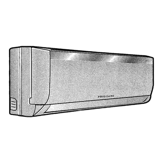
Product description Front panel frame Front panel Air filter (inside front panel) Horizontal airflow grille Vertical airflow grille • _ Temperature sensor (inside front panel) Panel Infra-red signal receiver Air iniet Drain hose connector and refrigerant gas connector Indoor Remote control Connector cable Detection valve Drain hose and refrigerant... - Page 34 Display panel (indoor unit) AUTO indicator; This indicator illuminates when the air conditioner is in AUTO operation. DEFROST indicator (For Cooling & Heating models only): This indicator illuminates when the air conditioner starts defrosting automatically or when the warm air control feature is activated in heating operation.
-
Page 35: Remote Control
Remote control Remote control operation t. Operation mode: Cool, Heat (Only for the models with cool/heat), DRY, FAN, and AUTO (Automatic). 2. Timer 24 hrs. 3, Internal temperature range selection: 17 ° - 30 o. 4. LCD 5. Night light operation mode. * (with 3 V, it reaches t 1 m) A ttention 1. -
Page 36: Remote Control Battery
Remote control battery conditioner emits a "beep" that indicates that a command has been To use the remote control, it is received and transmitted in the necessary to install two (R03/Ir03x2) indoor unit. alkaline AAA batteries. 3. When selecting the function of timer, the remote control sends When should the batteries be (automatically) a signal to the indoor... -
Page 37: Remote Control Description
Remote control description ON/OFF: Push this button to start the unit operation. Push the button again to stop the unit operation, TEMP_: Press the button to increase the indoor temperature setting. TEMPV: Press the button to decrease the indoor temperature setting. - Page 38 SLEEP; This button is used to start or stop the sleep function and/or to start the block function. Also, press this button once and the unit starts operating in sleep mode which keeps the room temperature comfortable and helps in the consumption energy.
-
Page 39: Sleep
LCD display indicators Auto air speed Air speed indicator Turbo* Sleep ON/OFF indicator: This ® indicator lit and flash once the 2H _ Temperature display remote control sends the signal to the indoor unit. Block Auto mode Horizontal airflow (up/down)* Cool mode Vertical airflow(left/right)* Dry mode... -
Page 40: How The Air Conditioner Works
How the air conditioner works Automatic operation When the Air Conditioner is ready for use, switch on the power and the OPERATION indicator lamp on the display panel of the indoor unit starts flashing. I. Use the MODE .select button to select AUTO. 2. -
Page 41: Airflow Direction Adjustment
DRY operation Attention The drymode will a utomatically select Due to the difference of the set thedrying o peration based o nthe temperature of the unit and the difference between theset actual indoor temperature, the Air temperature and theactual room Conditioner when in DRY mode will temperature, automatically operate many times... -
Page 42: Sleep Mode
SLEEP mode Attention Press the sleep button to activate the sleep mode. To deactivate, press the button again. Sleep function is only availaib[e in the Cool only mode: Coot/Heat and AUTO mode. • The indoor unit fan operates at a low velocity. -
Page 43: Optimal Operation
To set the stopping time 1. Push the TIMER OFF button and the remote controller will show TIMER OFF, the last set time for the stopping operation and the signal "h"wilt be shown on the DIGITAL DISPLAY area. You are now ready to reset the time of the STOP operation, 2. -
Page 44: How To Use The Indoor Unit
How to use the indoor unit Adjusting air flow direction Adjust the air flow direction properly otherwise, it might cause discomfort or cause uneven room temperatures. Adjust the horizontal louver using the remote controller. Adjust the vertical louver manually. Adjusting the vertical air flow direction (up - down) The air conditioner... - Page 45 The AIR DIRECTION and SWING buttons will be disabled when the air conditioner is not in operation (including when the TIMER ON is set). Do not operate the air conditioner for long periods with the air flow direction set downward in cooling or dry mode.
-
Page 46: Manual Operation
Manual operation (without remote control) Manual operation can be used temporarily in case you can not find the remote controller or its batteries are exhausted. !. Open and lift the front panel up to an angle until it remains fixed with a clicking sound, 2. -
Page 47: Maintenance
Maintenance Cleaning the indoor unit and remote controller 1. It is necessary to stop the air conditioner and disconnect the power supply before cleaning. 2, Use a dry cloth to wipe the indoor unit and remote controller, 3, A cloth dampened with cold water may be used on the indoor unit if it is very dirty. - Page 48 vacuum cleaner or water, After, dry Support for a couple of hours or until dry. Fresh frame 7. Insert the fresh air filter in its original place. 8. insert the high part of the air filter air filte_ (fresh air filter + Support frame) Fresh again in the unit keeping in mind air filter...
-
Page 49: Operation Tips
Operation tips The following events may occur during normal operation. Protection of the air conditioner, Compressor protection The compressor can't restart for 3 minutes after it stops. Anti-cold air (Co..o!ing and heating models only) The unit is designed not to blow cold air on HEAT mode, when the indoor heat exchanger is in one of the following three situations and the set temperature has not been reached. - Page 50 Apeculiar s mell c omes outfromtheindoor u nit. This iscaused b ytheindoor unit g iving offsmells p ermeated from building material, from furniture, orsmoke. Theairconditioner turnstoFAN onlymode fromCOOL o rHEAT (For cooling andheating models o nly) m ode. When indoor t emperature reaches thetemperature setting onairconditioner, compressor...
-
Page 51: Solution For Problems
Solutions for problems If your air conditioner malfunctions, check the following information to find solutions or probable causes of the failure. Do not try to repair the unit by yourself, if these solutions do not solve the failures; call your local service repair team. -
Page 52: I0. Technical Specifications
Technical specifications COOLING MODELS HEATING + COOLING MODELS... - Page 53 Notes...
- Page 54 Notes...
- Page 55 Notes _!_ii_i!_i_i_!!_i!!_i!_!i_i_i_!!i_i_!i!!_i_i_!_!i!_!_!_iii_i_!_i_ii_!!_!i!_!_i_!i!_ii_iii!i!_ii_i_!_i_ii_i_!!_!!i_...
- Page 56 ii:_ii!iil}i_i:i_iiiiii_!iiii:iiii:i:ii_iiiii?ii_ili$i:ili_i!!i_ ¸_ii_ii_iiii_i_i_ii_!!_ii!_i_!ii_{ii{_i_i_!_{i_ii_ii_iiiii!!_iii_!ii_ii_!iiiiiii_i{i_i_ii_i_iiii!_i_i_i!_i_! "_i:_ _ii;_ _i _ !,_i_ii:i_ !}ii_iii_i_iiiii_!!ii!_!i_ii_i£,_iii_ Z_ _ _ _ _ _i_ii_i_!iiKii_iii_i!_i_!_iiii_i F R IGI D_! R _ii_,,...
- Page 57 FRIGIDAIR ATENCION Lea todas las instrucciones antes de utilizar el aparato y guardelas para futuras...
-
Page 58: Bienvenido
Lea las instrucciones sobre instalaci6n y operaci6n antes de utilizar su acondicionador de aire y gu&rdelas en un lugar seguro para futuras consultas. Frigidaire una vez mAs fabrica Io mejor en Io que se refiere a electrodomesticos. Consejos ambientales E! material deI embalaje es reciclable. -
Page 59: Indice
Indice 01. Bienvenido ................... 02. Consejos ambientales ................03. indice ....................04. Precauciones de seguridad ..............05, Instalaci6n: 5.1 Eligiendo el local de instalaci6n ..........5.2 Lista de piezas ................5.3 instalaci6n de la unidad interna ........... 5.4 Instalaci6n de [a unidad externa ..........5.5 Conexi6n de ta tuberia refrigerante .......... - Page 60 - Operaciones Frio, Calor Y Solo Vent. - Uso de la deshumidificaci6n - Seco (Dry) - Ajuste de la direcci6n del flujo de aire - Uso de Dormir - Operaci6n del Temporizador (Timer) - Funcionamiento 6ptimo 6.7 Como usar la unidad interna ............- Ajuste la direcci6n de! flujo del aire - Ajuste de la direcci6n del aire verticalmente (arriba/abajo) - Para ajustar la direcci6n horizontal (izquierda/derecha)
-
Page 61: Precauciones De Seguridad
Precauciones de seguridad Normas de seguridad Las siguientes normas deberAn ser siempre respetadas para mayor seguridad: ° Aseg_rese de leer las siguientes advertencias antes de instalar el acondicionador de aire. • Aseg_rese de seguir todas las precauciones especificadas aqui, ya que incluyen importantes terminos relativos a [a seguridad, 1. - Page 62 5. Noda_e niutilice uncable de alimentaci6n et6ctrica no especificade para elproducto. Si elcable dealimentaci6n est& da_ado, elfabricante, suagente demantenimiento o similar persona autorizada deber_ substituirlo para evitar e lpeligro queelcable representa, 6. I',1o use eltomacorriente siesta flojoo daSado. 7. Instale s iempre uninterruptor autom_.tico y uncircuito d e alimentaci6n...
- Page 63 12. N olimpie elacondicionador aimconagua, Elagua podria penetrar enlaunidad y deteriorar suaislamiento, adem_s depeligro dedescargas el6ctricas. 13. No maneje el aparato con las manos mojadas o en lugares hQmedos. 14. Cierre las puertas y ventanas mientras el acondicionador de aire est&...
- Page 64 tambien en caso de tormenta o de condiciones clim&ticas adversas. 20. No beba el agua drenada del acondicionador de aire, esta contiene agentes contaminantes que pueden resultar daSinos para la salud. 21. Cuando vaya a reemplazar el filtro de aire, no toque las partes de metal del aparato.
-
Page 65: Eligiendo El Local De Instalaci6N
Eligiendo el local de instalaci6n Precauciones para la instalaci6n La instalaciSn en los siguientes lugares podria causar problemas. Si es inevitable realizarla en algunos de estos lugares, por favor consulte con su distribuidor local Electrofueguina. 1. Un lugar Ileno de aceites de m_tquina. 2. - Page 66 Unidad externa 1, Un ]ugar que sea conveniente para de 60cm la instalaci6n y no esta expuesto a de 30cm de 30cm vientos muy fuertes. Un lugar seco y ventilado. 2. Un lugar que soporte el peso de la unidad externa y pueda ser sostenida en posici6n vertical.
-
Page 67: Lista De Piezas
Lista de piezas Unidad tnterna Unidad Externa... - Page 68 MAs de 15cm Unidad Interna M&s de 12cm M_s de 12cm de Aire M_s de 60cm Filtro de 60cm M4s de 200cm Unidad Externa Atenci6n 1. lnstale ]a unidad interna a una altura de no menos de 2 m. Un recorrido minimo de 4 a 5 men las tuberias, requeddo para minimizar la vibraci6n y el ruido en exceso, Dos de las tres Direcciones (A, B o C en la gr_.fica)
-
Page 69: Instalaci6N De La Unidad Interna
Instalaci6n de la unidad interna Descripci6n de la placas de instalaci6n Contorno de Ia unidad intema 150ram del teeho Plata deinstalaci6n 120ram o m_s 120mm o m_s de la pared de ta pared Agujrro de Ia Agujero de Ia tuberia refrigeranta gerante _zquierda: _ 65... - Page 70 150mm de[techo t080 120ram o m&s 120ram orags de la pared de Ia pared Agu]ero de ta tuberia refrigerante izquierda: E_95 Cot_terno de la unidad intema Modelos 24000 Btu's Medelos 30000 Btu's 150ram del techo 1250 , 17_.._6_8 Aguje_ de ta ....
- Page 71 Haciendo la perforacion en la pared Pared 1. Determine la posici_n del orificio para [ Unid.E×terna I el tubo utilizando ta placa de p-'-.-J.4 tubo (0 65ram) de manera clue se ... "'"'" incline levemente hacia abajo. ::.. 2. Utilice simpre una tapa de tubo con apertura cuando perfore un list6n instalaci6n y taladre el orificio para el "_'"_'__"...
- Page 72 Fijaci6n de la unidad interna 1. Pase la tuberfa a trav6s del hueco Gaacho en la pared. 2. Ponga la parte superior de la u_,a en la parte trasera de la unidad interne sobre el gancho superior de laplaca de instalaci6n, mueva la unidad interne hacia los lados pare ver si se Ganoho enganch6 en forma segura.
- Page 73 Caja Tuberia conector y aislamiento colectora 1. Envuelva el tubo, el cable de oo,0o0,o,o,no de agua conexi6n y la manguera de drenaje Cable cuidadosamente con cinta (como se Espacio I del tubo muestra en la figura al lado). Tubeda 2, Debido a que e[ agua condensada >_de conexiSn de la parte trasera de la unidad Cinta...
-
Page 74: Instalaci6N De
Instalaci6n de la unidad externa 1. Instale la parte exterior de la unidad en una superficie rigida para evitar el exceso de ruido y vibraci6n. 2. Determine la direcci6n de salida del aire en donde no haya obstAculos. )CZC 3. Espeoialmente en Areas con viento, instAlelo de manera que reciba la menor cantidad de viento. - Page 75 Estableoimiento unidad externa Sujete la unidad externa en forma Entrada de aire_ ajustada, horizontal sobre un montaje de concreto o rigido con un bul6n y tuerca de 8 - 10 de diAmetro. i "t Salida de aire Instalacidn del empalme del drenaje Fije el sello en el codo det drenaje, inserte e! empaime del drenaje en el agujero bajo de la base de la unidad...
-
Page 76: Conexi6N De Ta Tuberia Refrigerante
Conexi6n de la tuberia refrigerante Trabajo de ensanchado La principal causa de fuga de liquido refrigerante, es debido a los defectos del trabajo de ensanche. Para hacerlo de manera correcta siga el siguiente procedimiento: 1, Corte la tuberia y los cables, A) Use et equipo de accesorios de la tubeda que ha comprado localmente. - Page 77 4, Trabajo de ensanche, A) Sostenga firmemente el tubo de cobre, en las dimensiones Troquet mostradas abajo. "-. I !J___ Tube_ia de cobre deI tornillo Ajuste de la conexi6n 1. Alinear el centro de los tubos. PrecauciOn: Un excesivo ajuste 2.
-
Page 78: Conexi6N Ei6Ctrica
Conexi6n el ctrica Regulaciones el_ctricas de seguridad para la instalaci6n 1. Si hay algSn problema el6ctrico 4. Aseg[irese que el acondicionador est_ con el polo a tierra= grave, los t6cnicos deber#.n rehusarse a instalar el 5. De acuerdo al diagrama de acondicionador de aire y exp]icarle conexiones electricas ubicadas en... - Page 79 Conectar el cable a la unidad interna 1. El cable de conexi6n interior o exterior debe ser tipo H07RN-E tapas de las 2. Levante el panel de 1aunidad, luego partes electricas retire to cubierta de cajcsel_drica destornillando el tornillo. 3. Remueva la tapas de los partes el6dricas.
- Page 80 9000 y 18000 Btu's 9000 y 18000 Btu_s MODELO FRIO MODELO FRIO Y CALOR "Conector A" "Conector B" "Conector A" "Conector B" Tabiero terminal de ta unidad interna Tablero terminal de fa unidad interna Hacia la Hacia Hacia la Hacia la unidad externa unidad externa unidad externa...
- Page 81 Conexi6n de! cable a la unidad externa 1, Remueva la tapa de tas partes el_ctricas de ta unidad externa, 2. Conecte los cables a tas terminates de manera que coincidan los ,TornilIo nSmeros de la unidad interna y externa. 3. Para prevenir el ingreso de agua forme una curva con el cable conector de las unidades.
- Page 82 9000 y 18000 Btu_s 9000 y 18000 Btu's MODELS FRIO MODELO FRIO Y CALOR "Conector A" "Conector B" "Conector A" "Conector B" Tablero terminal de ia unidad externa TabIero terminal de Ia unidad externa de cables _:_JTabIe_ de sables de cables "Conector C"...
-
Page 83: Purga De Aire
Precauci6n Despu_s de confirmar Io anterior, prepare Ia instalaci6n de la siguiente forma: 1. Tenga un circuito individual de potencia especfficamente para el acondicionador de aire. En cuanto al m6todo de cableado, reat[celo como Io indica el esquema circular ubicado en el interior de ta cubierta del control. 2. - Page 84 Purga de aire con bomba de vacio 1. Verifique que cada tubo (tanto los de liquido come los de gas) entre las unidades interior y exterior est6n conectados correctamente y que todo el cableado para la prueba de funcionamiento sea completo. Retire las tapas de valvula de servicio tanto del lado del gas como del liquido de la unidad externa.
- Page 85 Uso de la bomba de vacio Para el uso de la v6tvula Mani{old, re_:erirseal manual de operaci6n de 6slo. t. Aseg_rese de ajustar presi6n de la atm6sfera. completamente las tuercas, A, B, G, 7. Quite la manguera de carga de ta D, conecte la manguera de carga manguera de carga de baja de la v_lvula a un puerto de v&lvula...
-
Page 86: Seguridad El_Ctrica
Seg uridad electrica Realice el chequeo de seguridad ei_ctrico antes de terminar la lnstalaci6n: I, Resistencia de la aislaci6n, La resistencia de la aislaci6n debe ser mayor a 2M[_. 2. Polo a tierra. Despu6s de terminar este trabajo, mida su resistencia con el tester. -
Page 87: Prueba De Funcionamiento
Prueba de funcionamiento Realice esfa prueba despu_s de completar el control de fuga de gas y seguridad el6clrica. El test de funcionamiento deber6 durar m6s de 30 minutos. 1. Abra el panel y lev&nte!o hasta el 3. Revise si todas las funciones estan Angulo que to mantenga fijo. -
Page 88: Preparando El Aparato Para Hacerlo Funcionar
Preparando el aparato para hacerlo funcionar Entre en contacto con un especialista otros aparatos que generan calor para que instale el aparato. pues podria faltar ox[geno. Conecte el enchufe adecuadamente. Antes de hacer funcionar el Asegt]rese de que la unidad este acondicionador de aire, aseg0rese de fijada eficientemente. -
Page 89: Descripci6N Del Producto
Descripci6n del producto Marco del panel frontal Panel frontal Fiitro de aire (Dentro del panel frontal) Grilla de ¢orriente de aire horizontal Rendija vertical de corriente de aire Sensor de temperatura habitaci6n (Dentro del panel frontal) Panel de visualizaoi6n Receptor de seSal infra-rojo Entrada de aire Enchufe de la manguera... - Page 90 Panel de visualizaci6n (unidad interna) AUTO (Funci6n Autom&tica); Este indicador intermitente le avisara cuando el acondicionador de aire este en la funci6n autom_tica. SECO* (Dry): El acondicionador de aire comienza a descongelar automaticamente si la unidad e×tema se congela mientras opera la calefacci6n, * Nota: Solo para los modelos que tienen calefacci6n,...
-
Page 91: Como Funciona Et Control Remoto
Como funciona el control remoto Caracteristicas de/control remoto 1. Modo de operaci6n: FRIO, CALOR (solamente para los modelos con refrigeraci6n / calefacci6n), SECO, VENT. (Ventilador) y AUTO (autom&tico). 2. Funci6n de temporizador 24 horas. 3. Rango de selecci6n de la temperatura interna: 17°~ 30 °. -
Page 92: Cargar El Control Remoto
Cargar el control remoto limitando la capacidad de programaci6n de] aparato. Para usar el control remoto, sera necesario cargarlo con dos pilas Cada vez que se presiona un bot6n alcalinas (R03!Ir03x2) Tipo AAA. del control remoto, el acondicionador de aire emite un Se deber_ sustituir las pilas sonido (beep) que indica que se ha... -
Page 93: Descripci6N Del Control Remoto
Descripci6n del control remoto ENCENDER/APAGAR: Este bot6n encende o apaga la unidad. MAS ('remperatura): Presione la tecla/_k para incrementar la temperatura interna seleccionada o para ajustar el Temporizador en la direcci6n de las agujas del reloj. MENOS (Temperatura): Presione la tecla'_, para reducir la temperatura... - Page 94 Nota: Esta funci6n solo funciona VENT. (Velocidad del ventilador): Se usa para seleccionar una de cuando atguna de las funciones las cuatro velocidades del de TIMER estA activada, de Io ventilador: contrario no ocurrirA nada al presionar el boton "Cancel", AUTO I_ BAJA 1_ MEDIA...
-
Page 95: Turbo
Indicadores en la pantalla LCD Velocidad del aire Automaticalndicador de ia velocidad det aire Turbo* Dormir ® Indioador ON/OFF: Este 2_t _ Display de Temperatura indicador parpadear_, una vez el control remoto transmite la Bloqueo seSat a la unidad interna. Flujo del aire hacia arriba* Modo Auto Flujo dei aire hacia la... -
Page 96: Como Funciona El Acondicionador De Aire
Como funciona el acondicionador de aire Operaci6n AUTO (Automatica) Cuado el acondicionador de aire est_ listo para usar, enci_ndalo y la luz indi- cadora de la OPERACION en el panel de visualizaci6n de la unidad interna comenzar& a titilar. 1. Use MODO para seleccionar AUTO. 2. -
Page 97: Uso De La Deshumidificaci6N - Seco (Dry)
Atenci6n Uso de la deshumidificaci6n - SECO (Dry) I. En el modo de Ei modo SECO selecciona deshumidificaci6n, no es posible automaticamente esta operaci6n cambiar la velocidad del basada en la diferencia entre la ventilador. Dicha vetocidad es temperatura seleccionada y la del controlada autom6ticamente. -
Page 98: Uso De Dormir
Uso de DORMIR Atenci6n Presione la tecla DORMIR para activar et modo DORMIR. Para desactivar, ptesione de nuevo. La funci6n DORMIR s61ose encuentra En los modo frio: disponible con los modos de refrigeraci6n, calefacci6n y AUTO. • El ventilador de ta unidad interna funciona a baja velocidad. -
Page 99: Funcionamiento 6Ptimo
Para ajustar la hora de apagado 1. Por favor presione el b6ton TEMPOR, APAG. para cancelar todos los ajustes anteriores, 2. Presione el b6ton TEMPOR. APAG,. El control remoto mostrar_ TEMPOR. APAG. y la seSal "h" aparecer& en el panel de visualizaciSn. El control estA ahora listo para reestablecer la hora de apagado. -
Page 100: Como Usar La Unidad Interna
Como usar la unidad interna Ajuste la direcci6n del flujo del aire Ajuste la direcci6n del aire apropiadamente, de otra manera podria causar incomodidad diferentes temperaturas en una misma habitaci6n, Ajuste la rendija horizontal utitizando el control remoto. Ajuste la rendija vertical manualmente. - Page 101 Presione el botSn SWING en el control remoto, observar_s que las ventanillas horizontales comenzar_m a moverse autom&ticamente hacia arriba y hacia abajo. Para detener la funciSn y oprimalo nuevamente. El bot6n SWING ser#, deshabilitado cuando el equipo se encuentre apagado (inclusive cuando el temporizador est_ ajustado).
-
Page 102: Operacion Manual (Sin Control Remoto)
Operaci6n manual (sin control remoto) La operaci6n manual puede usarse temporalmente en caso de que no pueda encontrar el control remoto o que las baterias est6n agotadas. 1. Abra y levante el panel frontal hasta el #,ngulo en el que permanezca fijo, escuchar&... -
Page 103: Mantenimiento Y Cuidados
Mantenimiento y cuidados Limpiando la unidad interior y et control remoto 1. Es necesario apagar el acondJcionador de aire y desconectarlo antes de limpiarlo. 2. Use un paso seco para limpiar la unidad externa y el control remoto. 3. Un paso humedecido con agua frfa podr[a ser utilizado para limpiar la unidad interior, si es que esta se encuentra demasiado sucia. - Page 104 puede variar dependiendo de los modetos, vea en la flgura 1 y 2). Filtro Soporte del marco refrescante 5. Limpie el filtro refrescante de aire al deaire__ menos una vez at rues, y reemplacelo cada 4 o 5 meses. Limpielo usando una aspiradora, luego d6jelo secar en un lugar fresco "N£.._-_ rezrescante...
-
Page 105: Consejos De Operaci6N
Consejos de operaci6n Las siguientes situaciones podrfan ocurrir durante un funcionamiento normal: Protecci6n dei acondicionador de aire Protecci6n del compresor: El compresor no se puede reiniciar por 3-4 minutos despu_s de que se detiene. Antifrio (solo para los modelos con refrigeraci6n/calefacci6n): La unidad est_ disefiada para no enviar aire frio estando en el modo CALOR, cuando el intercambiador de ca]or interior esta en a[gunos de tas siguientes... - Page 106 Sale polvo de la unidad interna Esta condici6n es normal cuando el acondicionador de aire no ha sido utilizado por un largo tiempo, o puede suceder tambi_n la pdmera vez que se utilice. Un olor peculiar proveniente de la unidad interna Este es causado por los olores impregnados en los muebles, materiales de construcciSn o humo emanados por la unidad interna.
-
Page 107: Guia Para La Soluci6N De Problemas
Guia para la soluci6n de problemas Si su acondicionador de aire presenta problemas de funcionamiento, verifique a seguir las probables causas y soluciones. No intentar reparar la unidad usted mismo, Siestas sugerencias no solucionan su problema, llame el Servicio Autorizado Electrofueguina, El desempeSo del aparato es insatisfactorio. -
Page 108: Especificaciones Tecnicas
Especificaciones t6cnicas MODELO FRIO P_:n_o_ia_d::iate_r,_i_i ::: : :: ::_151 :::i _:i! :i ::_:_ii:i_i::ii:i::_:_i : _iTi:i:i:::i:::_:_: i:i_ :i ' _ _'!!i:ii_! ::Peso ne_o,unidag externa (kg_! : :::::::: ::::::::::::::::::::::::ii:::53 !::: : ; MODELO FRIO + CALOR Altura unload iatema (ram) ....;... - Page 109 Notas...
- Page 110 Notas...
- Page 111 Notas...
- Page 112 FRIGIDAIR...
Need help?
Do you have a question about the FAC12C2ABJW and is the answer not in the manual?
Questions and answers