Table of Contents
Advertisement
PART#
IB-2768
Operator's
Manual
I I:RAFTSMAN°I
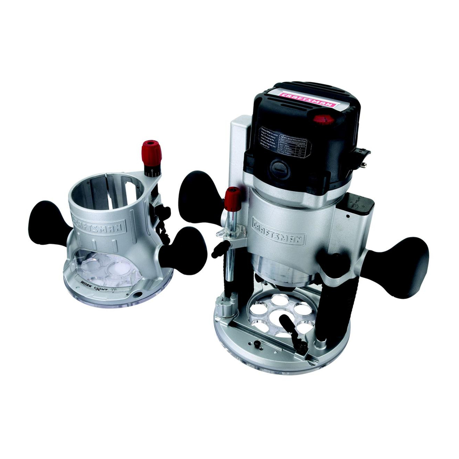
12.0 Amp Fixed Base Router
Model No. 320.2768
WARNING:
To reduce the risk of
injury, the user must read and
understand
the Operator's
manual
before using this product.
c_tus
• WARRANTY
• SAFETY
• UNPACKING
• DESCRIPTION
• OPERATION
• MAINTENANCE
• TROUBLESHOOTING
• ESPANOL
Sears Brands Management
Corporation,
Hoffman
Estates,
IL 60179
U.S.A.
www.craftsman.com
Advertisement
Table of Contents

Related Manuals for Craftsman 320.2768


Summary of Contents for Craftsman 320.2768
- Page 1 To reduce the risk of • UNPACKING injury, the user must read and • DESCRIPTION understand the Operator's manual • OPERATION before using this product. • MAINTENANCE • TROUBLESHOOTING • ESPANOL Sears Brands Management Corporation, Hoffman Estates, IL 60179 U.S.A. www.craftsman.com...
- Page 2 View and Part List page 35-39 Sears Repair Parts Phone Number Back Cover CRAFTSMAN ONE YEAR LIMITED WARRANTY FOR ONE YEAR from the date of purchase, this product is warranted against any defects in material or workmanship. With proof of purchase, defective product will be replaced free of charge.
- Page 3 The purpose of safety symbols is to attract your attention to possible dangers. The safety symbols and the explanations with them deserve your careful attention and understanding. The symbol warnings do not, by themselves, eliminate any danger. The instructions and warnings they give are no substitutes for proper accident prevention...
- Page 4 SYMBOL NAME DESIGNATION/EXPLANATION Volts Voltage Amperes Current Hertz Frequency (cycles per second) Watt Power Minutes Time Alternating Current Type of current ---==- Direct Current Type or a characteristic of current No Load Speed Rotational speed, at no load Class II Construction Double-insulated construction .../rain...
- Page 5 GENERAL POWER TOOL SAFETY WARNINGS WARNING: Read all safety warnings and instructions. Failure to follow the warnings and instructions may result in electric shock, fire and/or serious injury. • Know your power tool. Read the operator's manual carefully. Learn the applications, as well as the specific potential...
- Page 6 When operating a power tool outdoors, use an extension cord suitable for outdoor use. Use of a cord suitable for outdoor use reduces the risk of electric shock. If operating a power tool in a damp location is unavoidable, use a ground fault circuit...
- Page 7 POWER TOOL USE AND CARE Do not force the power tool. Use the correct power tool for your application. The correct power tool will do the job better and more safely at the rate for which it was designed. Do not use the power tool if the switch does not turn it on and off.
- Page 8 SERVICE SAFETY • Have your power tool serviced by a qualified repair person using only identical replacement parts. This will ensure that the safety of the power tool is maintained. If any part of this router is missing or should break, bend, or fail in any way;...
- Page 9 1=1/4 inches. To use cutter bits with a larger diameter, install and use a sub-base with a larger diameter opening (sold separately at Sears stores or other Craftsman outlets). Do not use large router cutter bits for freehand routing. Use of large...
- Page 10 • Only use router tables with on=board switch=controlled receptacles. Failure to use router tables with all the appropriate safety features could result in serious personal injury. • Disconnect the tool from the power source before making any adjustments or changing cutter bits.
- Page 11 Inspect the items carefully to make sure that no breakage or damage has occurred during shipping. If any of the items mentioned is missing, (refer to "PARTS LIST" illustration), return the router to your nearest Sears store to have the router replaced. ,_, WARNING: If any part is broken or missing, do not attempt to assemble...
- Page 12 KNOW YOUR ROUTER (Fig.l) Fig. 2 Motor housing Top Cap Speed Dial "Live Tool Indicator" Light Variable Speed Selection Chart Quick Clamp Motor Changing Motor Housing System Fixed Base Handles Spindle lock Non-Marring Sub-Base Self-Releasing Collets/Nuts System Replaceable Carbon Brushes ON/Off (Sold separately) Toggle Switch...
- Page 13 NOTE: Before attempting to useyourrouter, f amiliarize yourself withallofthe operating f eatures a ndsafety requirements. Yourfixedbase router h asa precision-built electric motor a ndit should only beconnected toa 120-volt, 60-Hz A Conlypower s upply (normal household current). Donotoperate ondirect c urrent ( DC). Thislarge voltage dropwillcause a lossofpower a ndthemotor w illoverheat.
- Page 14 100% Ball Bearings for smooth, efficient operation and long life. Base features Ergonomically Designed Handles for comfort and maximum control. Base features large Base Opening and large Chip Shield, combined with 3 LED Worklights on the motor to provide high visibility of bit and workpiece.
- Page 15 1-1/4 inches. To use cutter bits with larger diameters, use sub-bases with larger openings, sold separately at Sears stores or other Craftsman outlets. ,_, WARNING: Always turn the motor off and unplug the router before making any adjustments or installing accessories.
- Page 16 NOTE: To prevent damage to the tool, do not tighten the collet/nut without cutter bit installed. REMOVING THE CUTTER 1. Turn the motor off and unplug the router from the power source. Remove the motor from the fixed base. NOTE: See the instructions for installing and removing the motor housing from the fixed base on pages 17 and 18.
- Page 17 iNSTALLiNG THE ROUTER MOTOR iN THE BASE (Fig. 5) WARNING: Never use the router motor without installing it into either an approved fixed or plunge base. Failure to do so could result in serious personal injury and damage to motor. NOTE: Before installing the motor housing in the fixed base, have the collet/nut and router cutter bit you are going to use already installed in motor housing.
- Page 18 Set the motor upside down on its top cap with the collet pointing up and remove the cutter bit. WARNING: Always remove the cutter bit from collet/nut when the router is not being used. Leaving bits installed could result in accidents causing serious personal injury.
- Page 19 Open the motor clamp (A). Fig. 6 With the cutter bit already installed, press ir the coarse adjustment knob (B), and lower the motor into the base until the cutter bit is very close to the flat surface on which the base is sitting.
- Page 20 Contact the workpiece with the router and Fig. 8 cutter bit only after the router has reached full speed. Turn the router motor "OFF" and allow the cutter bit to come to a complete stop before removing the router and cutter bit from the workpiece.
- Page 21 NOTE: If the inner screws wear down or Fig. 10a require calibration: * Pull the lever up and turn it clockwise and then push the lever down (Fig.10a). * Turn the lever counterclockwise to secure the edge guide (Fig.10b). Electronic Variable Speed Control...
- Page 22 DIAL SETTING APPLICATION 10,000 Non-ferrous metal, hardwoods, larger 13,000 diameter cutter bits 16,000 19,000 Softwoods, plastics, countertops, 22,000 smaller diameter cutter bits 25,000 The speed charts above indicate the relationship between speed settings and the cutting application. Exact settings are determined by operator experience reference, and also by recommendations...
- Page 23 To be certain that your depth settings are correct, always make test cuts in scrap material similar to your workpiece before beginning the final cutting operation. Remember, knowing the right depth for each cut comes with routing experience. EDGE ROUTING {Fig.
- Page 24 3. Tobegin yourcut, g radually lower t hecutter Fig.13 bitintotheworkpiece until t hesub-base is flush withtheworkpiece (see Fig. 1 2a, 1 2b). 4. When thecutiscompleted, turnthemotor "Off"andallowthecutterbitcome toa complete s topbefore removing i t from the workpiece. 5. Unplug t herouter f romthepower s ource, place therouter u pside down onthe worktable, andinspect thefinished cutin theworkpiece,...
- Page 25 NOTE: Making a single deep cut is never advisable. Smaller-diameter bits are easily broken by too much side thrust and torque. Larger bits will cause a rough cut and be difficult to guide and control. For these reasons, do not exceed 1/8- in.
- Page 26 FEEDING THE ROUTER (Fig. 16) The secrets to professional Fig. 16 ROUTER FEED DIRECTION routing are a careful set-up for the cut, selecting the proper depth of cut, knowing the cutter bit reacts in your workpiece, and the rate and direction of feed of the router.
- Page 27 When the guide is positioned as shown in Fig. 17a, the router travel should be from left to right and clockwise around GUIDE OUTSIDE curves. BIT ROTATION If there is a choice, the set-up in Fig. 17 is Fig. 17 _"...
- Page 28 by the sound of the motor. Its usual high-pitched whine will sound lower and stronger as it loses speed. Holding the router against the workpiece will also come more difficult. FEEDING TOO SLOWLY (Fig. 18a} When you feed the cutter bit too slowly, the rotating cutter bit does not cut into new wood rapidly enough to take a bite.
- Page 29 TO ADJUST DEPTH WITH DEPTH=ADJUSTMENT WRENCH (Figs. 21, 21a) NOTE: The Depth-Adjustment Wrench supplied is used to adjust the depth when the Fig. 21 router is fixed to the router table (Model No. 320.28180), sold separately (Fig. 21). WARNING: Always read and follow all directions for mounting the router to a router...
- Page 30 All other parts represent an important part of the double-insulation system and should be serviced only by a qualified Craftsman service technician. _1, WARNING: For your safety, always turn off the switch and unplug the router motor from the power source before performing any maintenance or cleaning.
- Page 31 REPLACEMENT OF CARBON BRUSHES (Fig. 22) Replacement brush sets are available through Fig. 22 Sears Parts and Repair Centers. Unplug the router motor before inspecting or replacing brushes. Replace both carbon brushes when either has less than 1/4-in. length of carbon remaining, or if the spring or wire is damaged...
- Page 32 WARNING: The use of attachments or accessories that are not recommended for this tool might be dangerous and could result in serious injury. Sears and other Craftsman outlets offer a large selection of Craftsman router accessories designed for specific routing applications.
- Page 33 1/8-in. 3/8-in. 1/4-in. straight stn _ight straight straight 3/4-in. 5/16-in. 1/2-in. '_ straight straight straight dovetail 3/8-in. dove tail 1/2-in. dove tail 1/2-in. round nose round nose 1/2-in. 90 d v groove v groove 1/2 x 1-in. 3/8xl/2-in. flush trim flush trim flush trim 1/2-in.
- Page 34 1/2-in. bead and cove bead cove 1/16-in. cove & bead classic cove with bead 1/4-in. roman ogee Roman ogee ..J_"l 3/8-in. rabbeting rabbeting 1/4-in. veining veining 1/2-in. core box core box 1/2-in. mortising mortising 1/4-in. panel pilot panel pilot 1-3/8-in.
- Page 35 12.0 Amp Fixed Base Router Model No. 320.2768 The Model Number will be found on the Nameplate attached to the motor unit. Always mention the Model Number when ordering parts for this tool. 2768 Manual_Revised_11-0307 Page 35...
- Page 36 12.0 Amp Fixed Base Router Model No. 320.2768 The Model Number will be found on the Nameplate attached to the motor unit. Always mention the Model Number when ordering parts for this tool. Explosive drawing Back cover 2768 ManuaLRevised_11-0307 Page 36...
- Page 37 5610220000 Screw 3321133000 Rear Cover 3121518000 Transparent 5610017000 Tapping Screw 4890638000 Speed Adjustor 5620017000 Screw 3120537000 Brush Cover 4960019000 Carbon Brush Assy 2800005000 Brush Holder Assy 5610106000 Tapping Screw 5610059000 Screw 2823115000 Switch Assy 3122851000 Seal Ring 4810002000 Power Cord Assy 4930008000 Sleeve 4930038000...
- Page 38 5630179000 3551635000 Spindle Lock 3660174000 Stop Spring 5620061000 Screw 3421190000 Spindle Lock Cover 5620069000 Screw 2823121000 Collet Assembly 5620041000 Screw 3320460000 Adjusting Knob 3123281000 Indicator 3550841000 Shaft 5660005000 "E" Ring 3660498000 Spring 3126054000 Handle Sleeve 3705047000 Lever 5620466000 Screw 5620467000 Screw 5650407000 Wave Washer...
- Page 39 5650337000 Washer 5620067000 Screw 3402220000 Depth Adjusting Lever 2823125000 Collet Assy 3550588000 Guiding 3703925000 Fence 5650013000 Washer 5650015000 Spring Washer 5620050000 Screw 3402471000 Wrench 3123286000 Vaccum Adapter 2768 Manual_Revised_11-0307 Page 39...
- Page 40 Your Home For troubleshooting, product manuals and expert advice: managemylife www.managemylife.com For repair - in your home - of all major brand appliances, lawn and garden equipment, or heating and cooling systems, no matter who made it, no matter who sold it! For the replacement parts, accessories and owner's manuals that you need to do-it-yourself.
Need help?
Do you have a question about the 320.2768 and is the answer not in the manual?
Questions and answers