Table of Contents
Advertisement
Quick Links
Download this manual
See also:
User Manual
Advertisement
Table of Contents

Related Manuals for Altinex Distribution Amplifier DA1506RT


Summary of Contents for Altinex Distribution Amplifier DA1506RT
- Page 1 DISTRIBUTION AMPLIFIERS MANUAL PART NUMBER: 400-0016-004 DA1506RT 2-IN, 6-OUT VGA DISTRIBUTION AMPLIFIER USER’S GUIDE...
-
Page 2: Table Of Contents
DIAGRAM 1: TYPICAL SETUP ...4 DIAGRAM 2: INTERNAL VIEW ...5 DIAGRAM 3: CONNECTOR PINOUTS ...6 INSTALLING YOUR DA1506RT... 7 OPERATION ... 7 TROUBLESHOOTING GUIDE... 7 ALTINEX POLICIES ... 7 LIMITED WARRANTY/RETURN POLICIES ...7 CONTACT INFORMATION ...7 400-0016-004 DISTRIBUTION AMPLIFIERS Page... -
Page 3: Precautions / Safety Warnings
Do not place heavy objects on top of the DA1506RT. If the DA1506RT is to be mounted to a table or wall, use only ALTINEX-made mounting accessories. To turn off the main power, be sure to remove the power cord. -
Page 4: About Your Da1506Rt
DA1506RT is great for desktop use, but can also rack-mounted using hardware. TECHNICAL SPECIFICATIONS Specifications are subject to change. www.altinex.com for up-to-date information. FEATURES/ DA1506RT DESCRIPTION GENERAL Input Connectors 15-pin HD female (2) Output Connectors 15-pin HD female (6) -
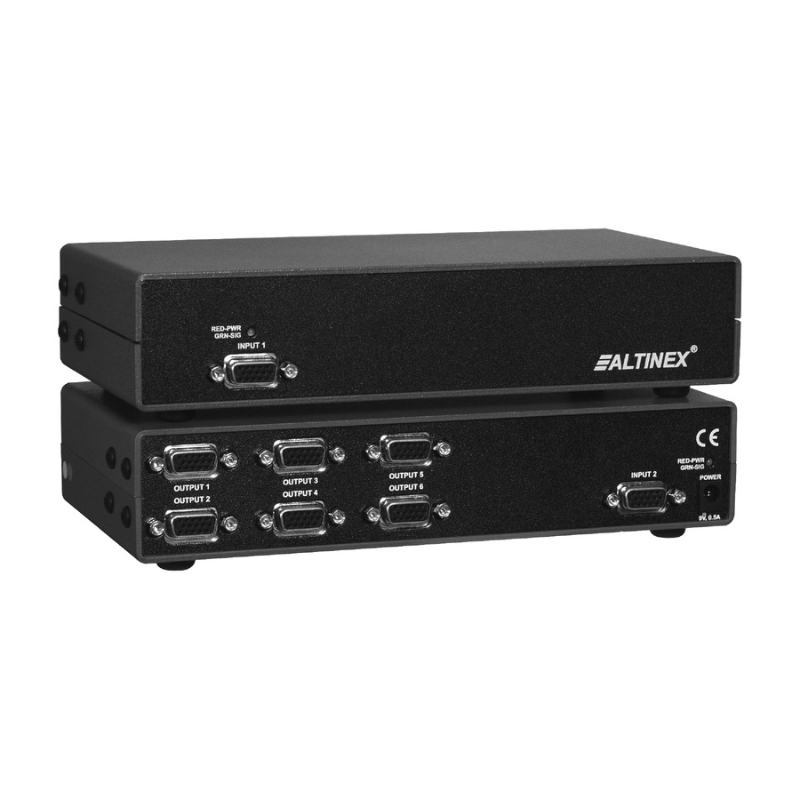
Page 5: Product Description
PRODUCT DESCRIPTION FRONT VIEW INPUT1 REAR VIEW OUTPUTS 1-6 APPLICATION DIAGRAMS DIAGRAM 1: TYPICAL SETUP 400-0016-004 DISTRIBUTION AMPLIFIERS INPUT2 DA1506RT POWER... -
Page 6: Diagram 2: Internal View
DIAGRAM 2: INTERNAL VIEW 2-IN 6-OUT VGA-XGA DA PLUG AND PLAY FRONT 15-PIN HD BACK PLUG AND PLAY POWER 9V, 0.5A 400-0016-004 DISTRIBUTION AMPLIFIERS AUTO SWITCH SIGNAL POWER DETECT OUT 1 OUT 2 OUT 3 15-PIN HD OUT 4 OUT 5 OUT 6... -
Page 7: Diagram 3: Connector Pinouts
DIAGRAM 3: CONNECTOR PINOUTS INPUT CONNECTORS Pin No. PIN ASSIGNMENTS Green Blue Ground Ground Ground Ground Ground VESA +5V IN Ground Ground VESA SDA Horizontal Sync Vertical Sync VESA SCL Table 4. The DA1506RT Input Pins 400-0016-004 DISTRIBUTION AMPLIFIERS OUTPUT CONNECTORS Pin No. -
Page 8: Installing Your Da1506Rt
Please make sure that the input amplitude of analog signal is less than 1.5 Vp-p. Please use the ALTINEX-supplied external adapter (9V, 500mA). Please make sure that proper quality of cables is used. We recommend ALTINEX-made cables for best results.
Need help?
Do you have a question about the Distribution Amplifier DA1506RT and is the answer not in the manual?
Questions and answers