Advertisement
Quick Links
Download this manual
See also:
Installation Manual
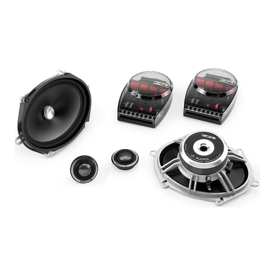
ZR570-CSi
5-inch x 7-inch (125 x 180 mm) 2-Way Component System
o w n e r ' s m a n u a l
Thank you for choosing a JL Audio Evolution ZR Component System
for your automotive sound system. With proper installation, your
new speakers will deliver years of listening pleasure.
We strongly recommend that you have your new Evolution speakers
installed by your authorized JL Audio dealer. The installation
professionals employed by your dealer have the necessary tools
and experience to disassemble your interior panels, install your
new speakers and reassemble your vehicle properly. If you prefer to
perform your own installation, please read this instruction manual
completely before beginning the process.
Advertisement

Related Manuals for JL Audio ZR570-CSi


Summary of Contents for JL Audio ZR570-CSi
- Page 1 5-inch x 7-inch (125 x 180 mm) 2-Way Component System o w n e r ’ s m a n u a l Thank you for choosing a JL Audio Evolution ZR Component System for your automotive sound system. With proper installation, your new speakers will deliver years of listening pleasure.
- Page 2 0.46 in. /11.7 mm 0.39 in. / 9.9 mm 0.85 in. / 21.6 mm Crossover Network Physical Dimensions Height (A) 5.86 in. / 148.9 mm Width (B) 4.17 in. / 105.8 mm Depth (C) 1.68 in. / 42.8 mm JL AUDIO ZR570-CSi...
- Page 3 A l l s p e c i f i c a t i o n s a r e s u b j e c t t o c h a n g e w i t h o u t n o t i c e . JL AUDIO ZR570-CSi...
- Page 4 The crossover network has been engineered Do not substitute different crossover networks into to shape the system response... additional filters your ZR System. Do not use crossover networks may degrade performance. intended for different ZR models. JL AUDIO ZR570-CSi...
- Page 5 Diagram A: Standard Wiring Diagram Amplifier Output Diagram B: Bi-Wire (Bi-Amp) Wiring Diagram Woofer Tweeter Amplifier Amplifier Output Output JL AUDIO ZR570-CSi...
- Page 6 Should this occur while listening to the audio system, simply reduce the volume for a few seconds and the protection circuit will reset itself automatically. JL AUDIO ZR570-CSi...
-
Page 7: Speaker Placement Considerations
Higher mounting locations often result in extreme near-side soundstage bias which compromises the stereo listening experience. Less Desirable Speaker Placement More Desirable Speaker Placement JL AUDIO ZR570-CSi... -
Page 8: Woofer Installation
If you are unsure about any of these issues, contact your JL Audio dealer for installation assistance. Your new speakers have been designed to install, without modifications, into most vehicles that accept a 5x7-inch (125 x 180 mm) speaker. - Page 9 WARNiNG Hand-tighten the screws evenly in a criss- cross pattern to avoid bending the speaker frame or stripping the mounting clips. Diagram C: Factory Location Woofer Installation JL AUDIO ZR570-CSi...
-
Page 10: Tweeter Installation
Use the supplied #6 x 5/8-inch sheet metal screws to secure the fixture as shown in Diagram F (hand-tighten). Run the tweeter's wires through the hole and insert the tweeter until it snaps into place. JL AUDIO ZR570-CSi... - Page 11 Diagram E: Flush-Mount Tweeter Installation Diagram F: Surface-Mount Tweeter Installation JL AUDIO ZR570-CSi...
- Page 12 All warranty returns should be sent to JL Audio freight prepaid through an authorized JL Audio dealer and must be accompanied by proof of purchase (a copy of the original sales receipt.) Direct returns from consumers or non-authorized dealers will be refused unless specifically authorized by JL Audio with a valid return authorization number.
Need help?
Do you have a question about the ZR570-CSi and is the answer not in the manual?
Questions and answers