
Related Manuals for Sharp XV-Z91E


Summary of Contents for Sharp XV-Z91E
- Page 1 XV - Z91E PROJECTOR OPERATION MANUAL PROJEKTOR BEDIENUNGSANLEITUNG PROJECTEUR MODE D’EMPLOI PROJEKTOR BRUKSANVISNING PROYECTOR MANUAL DE MANEJO PROIETTORE MANUALE DI ISTRUZIONI PROJECTOR GEBRUIKSAANWIJZING...
- Page 2 This equipment complies with the requirements of Directive 89/336/EEC and 73/23/EEC as amended by 93/68/EEC. Dieses Gerät entspricht den Anforderungen der EG-Richtlinien 89/336/ EWG und 73/23/EWG mit Änderung 93/68/EWG. Ce matériel répond aux exigences contenues dans les directives 89/ 336/CEE et 73/23/CEE modifiées par la directive 93/68/CEE. Dit apparaat voldoet aan de eisen van de richtlijnen 89/336/EEG en 73/ 23/EEG, gewijzigd door 93/68/EEG.
- Page 3 SPECIAL NOTE FOR USERS IN THE U.K. The mains lead of this product is fitted with a non-rewireable (moulded) plug incorporating a 3A fuse. Should the fuse need to be replaced, a BSI or ASTA approved BS 1362 fuse marked and of the same rating as above, which is also indicated on the pin face of the plug, must be used.
-
Page 4: Operation Manual
Before using the projector, please read this operation manual carefully. OPERATION MANUAL ENGLISH IMPORTANT For your assistance in reporting the loss or theft of your Model No.: XV - Z91E Projector, please record the Serial Number located on the bottom of the projector and retain this information. Serial No.: Before recycling the packaging, please be sure that you have checked the contents of the carton thoroughly... -
Page 5: Caution Concerning The Lamp Replacement
1 HEURE AVANT DE PROCEDER AU REMPLACEMENT DE LA LAMPE. UNIT TYPE BQC-XVZ90+++1 ONLY. UV RADIATION : CAN CAUSE NE REMPLACER QUE PAR UNE LAMPE SHARP DE TYPE BQC-XVZ90+++1. EYE DAMAGE. TURN OFF LAMP BEFORE SERVICING. RAYONS ULTRAVIOLETS : PEUVENT ENDOMMAGER LES YEUX. -
Page 6: Important Safeguards
IMPORTANT SAFEGUARDS ATTENTION: Please read all of these instructions before you operate your Projector for the first time. Save these instructions for future reference. For your own protection and prolonged operation of your Projector, be sure to read the following “IMPORTANT SAFEGUARDS”... -
Page 7: Caution Concerning The Lamp Unit
A MANIPULER AVEC PRECAUTION, SE REPORTER AU MODE D’EMPLOI. Cautions Concerning the Setup of the Projector For minimal servicing and to maintain high image quality, SHARP recommends that this projector be installed in an area free from humidity, dust and cigarette + 35˚C... - Page 8 IMPORTANT SAFEGUARDS Temperature Monitor Function If the projector starts to overheat due to setup problems, “TEMP.” and “ ” will blink in the lower-left corner of the picture. If the temperature continues to rise, the lamp will turn off, the TEMPERATURE WARNING indicator on the projector will blink, and after a 90-second cooling-off period the power will shut off.
-
Page 9: Table Of Contents
Contents Turning On/Off the On-screen Display ..36 Selecting the Signal Type ......36 Important Information Setting the Video Signal (VIDEO menu only) ......37 IMPORTANT SAFEGUARDS ....3 Selecting a Background Image ....37 Contents ........... 6 Adjustments for the Screen Position Outstanding Features ...... -
Page 10: Outstanding Features
Outstanding Features 1. DMD™* (Digital Micromirror Device) Chip The DMD Chip allows for a higher contrast image. It enables smoother expression of details of an image, and high picture quality for an exciting theatre experience. Digital Light Processing, DLP, Digital Micromirror Device and DMD are trademarks of Texas Instruments. 2. -
Page 11: Part Names
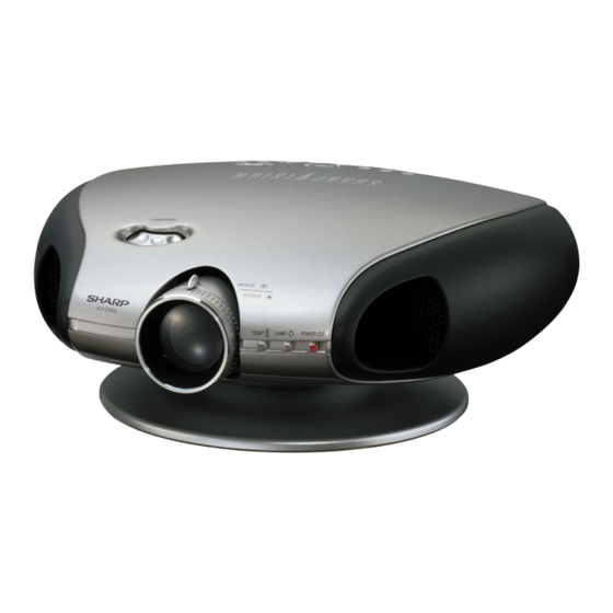
Part Names Numbers next to the part names refer to the main pages in this manual where the topic is explained. Projector Front and Top View Lens shift dial TEMPERATURE WARNING indicator Zoom knob LAMP REPLACEMENT indicator Exhaust ventilative hole POWER indicator Focus ring Exhaust ventilative hole... -
Page 12: Part Names
Part Names Numbers next to the part names refer to the main pages in this manual where the topic is explained. Projector Side and Rear View Remote control sensor Intake ventilative hole Intake ventilative hole INPUT 2 COMPONENT/ INPUT 3 S-VIDEO terminal RS-232C port RGB port (4-pin Mini DIN) -
Page 13: Remote Control
Part Names Remote Control Front View Top View POWER buttons (ON/OFF) KEYSTONE button MENU button ENTER button ADJUSTMENT buttons (∂/ƒ/ß/©) UNDO button INPUT 1 button INPUT 3 button INPUT 2 button INPUT 4 button RESIZE button AUTO SYNC button PICTURE SETTING button RGB/COMP. -
Page 14: Supplied Accessories
Supplied Accessories Remote control Two AA size batteries Power cord (For Europe except U.K.) (For U.K., Hong Kong (For Australia and Singapore) and New Zealand) • Use the power cord that corresponds to the wall outlet in your country. Computer-RGB 21 pin RCA Video cable cable... -
Page 15: Connections
Connections Power Supply Connecting the Power Cord Plug the supplied power cord into the AC socket on the back of the projector. Power cord CAUTION • Make sure the power cord is firmly connected into the AC socket. • The projector will enter the standby mode as you re-plug it into the AC socket, when unplugging the power cord after turning the power off by pressing the POWER button. -
Page 16: Connecting To A Dvd Player And Dtv Decoder
Connecting to Video Equipment Projector S-video cable (commercially available) 2 To S-video output terminal Video cable 2 To video output terminal VCR, Laser disc player, DVD player or DTV decoder Connecting to a DVD Player and DTV Decoder Connecting to a DVD player and DTV decoder with Component output (for INPUT 1) 1 Connect each RCA connector of a component cable to the corresponding RCA INPUT 1 terminals on the projector. -
Page 17: Connecting To A Computer
Connecting to a DVD Player and DTV Decoder Connecting to a DTV decoder with analog RGB output 1 Connect the computer-RGB cable to the INPUT 2 COMPONENT/RGB port. 2 Connect the other end to the corresponding terminal on a DTV decoder. When connecting this projector to analog RGB output of the DTV decoder, select “Component”... -
Page 18: Operating The Remote Control
• The arrows (→, ↔) in the configuration above indicate the direction of the signals. • A Macintosh adaptor may be required for use with some Macintosh computers. Contact your nearest Sharp Authorised Projector Dealer or Service Centre. Operating the Remote Control... -
Page 19: Power On/Off
Power ON/OFF Press POWER ON. • The blinking green LAMP REPLACEMENT indicator shows that the lamp is warming up. Wait until the indicator stops blinking before operating the projector. • If the power is turned off and then immediately turned on again, it may take a short while before the lamp turns on. -
Page 20: Setting Up The Screen
Setting Up the Screen Using the Swivel Stand You can adjust the angle and direction of the projected image by using the Swivel Stand. 1 Unlock the lever on the Swivel Stand. 2 Adjust the angle and direction of the projected image as you want by lifting up the projector and rotating the projector on the Swivel Stand. -
Page 21: Using The Lens Shift
Using the Lens Shift The picture can be adjusted within the shift range of the lens by rotating the lens shift dial on the top of the projector using your finger. Projector Projected Image Lens shift dial DOWN DOWN... -
Page 22: Keystone Correction
Keystone Correction This function can be used to adjust the Keystone settings. • For details about using the menu screen, see page 26. Description of 2D Keystone Correction Selected item Description H Keystone Horizontally adjusts the keystone settings. V Keystone Vertically adjusts the keystone settings. -
Page 23: Placement Of The Projected Image Using The Keystone Correction
Placement of the Projected Image Using the Keystone Correction Place the projector at a distance from the screen that allows images to be projected onto the screen by referring to “Adjusting the Projection Distance” on pages 21 and 22. : Screen area 1 Project the test pattern of the Keystone correction function onto the screen. -
Page 24: Adjusting The Projection Distance
Adjusting the Projection Distance • Refer to pages 19 and 20 about the function of Keystone correction and placement of projector using the correction. • Decide the placement of the projector referring to the figures on the table and the diagram below according to the size of your screen and the input signal. - Page 25 Adjusting the Projection Distance Upper and Lower Lens Shift Position • This projector is equipped with a lens shift function that lets you adjust the projection height. • Adjust it to match the setup configuration. • The screen can be moved maximum the length of one screen vertically using the lens shift. •...
-
Page 26: Image Projection
Ceiling-mount Projection • It is recommended that you use the optional Sharp ceiling-mount bracket for this installation. • Before mounting the projector, remove the Swivel Stand. -
Page 27: Using The Operation Buttons
Using the Operation Buttons Selecting the Input Signal Source Press INPUT on the projector, INPUT 1, INPUT 2, INPUT 3 or INPUT 4 on the remote control to select the desired input mode. • When no signal is received, “NO SIGNAL” will be displayed. When a signal that the projector is not preset to receive is received, “NOT REG.”... - Page 28 Adjusting the Picture Aspect Ratio Input Signal Output screen image STRETCH NORMAL BORDER Projects the image fully Projects the image on Projects the image on DVD/ VIDEO COMPUTER Image Type on a screen while the screen whose the screen whose upper maintaining the aspect surrounding areas are and lower areas are cut...
-
Page 29: Using The Menu Screen
Using the Menu Screen Basic Operations This projector has two sets of menu screens that allow you to adjust the image and various projector settings. These menu screens can be operated from the projector or the remote control with the following procedure. 1, 7 2, 3, On-screen Display... -
Page 30: Menu Bars
Menu Color Opaque purposes only. Translucent • “Color”, “Tint”, and “Sharp” do not appear when “RGB” is selected in INPUT 2 mode. • Only the items highlighted in the tree charts above can be adjusted. • To adjust the items under the sub menu, press after selecting the sub menu. -
Page 31: Sub Menu
Sub menu Main menu Sub menu Picture ( Contrast Language ( English Bright Deutsch Color Español Tint Nederlands Français Sharp Italiano Blue Svenska Reset Português CLR Temp 5500k 3D Progressive 6500k 3D Progressive 7500k 3D Progressive 8500k PRJ Mode (... -
Page 32: Adjusting The Picture
On-screen Display e. g. (VIDEO input in INPUT 3 or 4 mode) • “Color”, “Tint” and “Sharp” do not appear for RGB input in INPUT 2 mode. • For details on “Gamma”, see “Gamma Correction Function” on page 31. -
Page 33: Adjusting The Colour Temperature
Adjusting the Picture Adjusting the Colour Temperature This function allows for selecting the desired colour temperature from six settings. With the lower value selected, the projected image becomes warmer, reddish and incandescent-like while with the higher value, the image becomes cooler, bluish and fluorescent-like. -
Page 34: Gamma Correction Function
Adjusting the Picture Gamma Correction Function Gamma is an image quality enhancement function. Four gamma settings are available to allow for differences in the brightness of the room. Description of Gamma Modes Selected Mode Description Standard Standard picture without gamma correction 2, 3 1, 5 Black Detail... -
Page 35: Picture Setting Function
Adjusting the Picture Picture Setting Function This function stores all items set in “Picture”. Five settings can be stored separately in “Memory 1” to “Memory 5”. Each stored setting is reassigned to each input mode (INPUT 1 to INPUT 4). Even when the input mode or signal is changed, you can easily select optimal settings from the stored settings. -
Page 36: Adjusting The Computer And Dvd/Dtv Images
Adjusting the Computer and DVD/DTV Images When displaying computer patterns which are very detailed (tiling, vertical stripes, etc.), interference may occur between the DMD pixels, causing flickering, vertical stripes, or contrast irregularities in portions of the screen. Should this occur, adjust “Clock”, “Phase”, “H-Pos”... -
Page 37: Special Modes Adjustment
Adjusting the Computer and DVD/DTV Images Special Modes Adjustment Ordinarily, the type of input signal is detected and the correct resolution mode is automatically selected. However, for some signals, the optimal resolution mode in “Special Modes” on the “Fine Sync” menu screen may need to be selected to match the computer display mode. -
Page 38: Auto Sync Adjustment
Adjusting the Computer and DVD/DTV Images Auto Sync Adjustment • Used to automatically adjust a computer image. • Select whether the image is to be synchronized automatically when switching the signal with “ON” or “OFF”. OFF ( 2,3,4 • Synchronized adjustment is not automatically 1, 5 performed. -
Page 39: Turning On/Off The On-Screen Display
Turning On/Off the On-screen Display This function allows you to turn on or off the on-screen messages that appear during input select. Description of OSD Display Selected item Description All On-screen Display are displayed. ON ( 2,3,4 INPUT is not displayed. 1, 5 OFF ( 1 Press MENU. -
Page 40: Setting The Video Signal (Video Menu Only)
Setting the Video Signal (VIDEO menu only) The video input system mode is preset to “Auto”; however, it can be changed to a specific system mode if the selected system mode is not compatible with the connected audiovisual equipment. 1 Press MENU. The “Picture” menu screen appears. 2,3,4 2 Press to display the “Options”... -
Page 41: Adjustments For The Screen Position And Size
Adjustments for the Screen Position and Size You can adjust settings according to the position and size of the screen. Description of Adjustment Items Selected item Description Digital Shift Adjusts the vertical position of the image. 2,3,4 Subtitle Adjusts the vertical size of the image. 1, 5 Reset Digital Shift and Subtitle adjustments are... -
Page 42: Subtitle Setting
Adjustments for the Screen Position and Size Subtitle Setting With this function, you can adjust the vertical size of the display to allow for subtitles. Description of Subtitle Setting button button 2,3,4 1, 5 The image is compressed by The image is enlarged by adjusting the vertical size of the adjusting the vertical size of the display. -
Page 43: Selecting The Menu Screen Position
Selecting the Menu Screen Position This function allows you to select the desired position of the menu screen. Description of Menu Position Selected Description item Center The menu is displayed on the centre of the image. 2,3,4 Upper Right The menu is displayed on the upper right of the image. Lower Right The menu is displayed on the lower right of the image. -
Page 44: Automatic Power Shut-Off Function
Automatic Power Shut-off Function When no input signal is detected for more than 15 minutes, the projector will automatically shut off. The on-screen message on the left will appear five minutes before the power is automatically turned off. Description of Automatic Power Shut-off Selected Description 2,3,4... -
Page 45: Reversing/Inverting Projected Images
Reversing/Inverting Projected Images This projector is equipped with a reverse/invert image function which allows you to reverse or invert the pro- jected image for various applications. Description of Projected Images Selected item Description Front Normal image 1, 5 Ceiling Front Inverted image Rear Reversed image... -
Page 46: Advanced Picture Adjustment
Advanced Picture Adjustment Detailed picture adjustments can be made in addition to the adjustments on the normal menu screen. Selected button button R-Contrast For less contrast of red For more contrast of red colour colour G-Contrast For less contrast of For more contrast of green green colour colour... -
Page 47: Lamp/Maintenance Indicators
• Clogged ventilative hole. • Clean the ventilative holes. (See page 49.) • Cooling fan breakdown. • Take the projector to your nearest Sharp • Internal circuit failure. Authorised Projector Dealer or Service Centre for repair. LAMP REPLACE- The lamp does not •... -
Page 48: Lamp Maintenance
The power will automatically turn off • Lamp has been used for over 2,500 replaced at your nearest Sharp and the projector will enter standby hours. Authorised Projector Dealer or mode. -
Page 49: Replacing The Lamp
Carefully change the lamp by following the steps on the next page. If the new lamp does not light after replacement, take your projector to the nearest Sharp Authorised Projector Dealer or Service Centre for repair. Purchase a replacement lamp unit (lamp/cage module) of the current type BQC-XVZ90+++1 from your nearest Sharp Authorised Projector Dealer or Service Centre. - Page 50 Replacing the Lamp Removing and installing the lamp unit CAUTION • Be sure to remove the lamp cage by the handle. Do not touch the glass surface of the lamp cage or the inside of the projector. • To avoid injury to yourself and damage to the lamp, carefully follow the steps below. •...
- Page 51 Replacing the Lamp Tighten the user Plug the power cord. Attach the lamp unit service screw to fasten cover. the lamp cage cover. Press POWER ON on the projector to reset the lamp timer. Press order. Then press “LAMP 0000H” is displayed on the screen.
-
Page 52: Cleaning The Ventilative Holes
Cleaning the Ventilative Holes • This projector is equipped with ventilative holes to ensure the optimal operating condition of the projector. • Periodically clean the ventilative hole by vacuuming it off with a vacuum cleaner. • The ventilative holes should be cleaned every 100 hours of use. Clean the ventilative holes more often when the projector is used in a dirty or smoky location. -
Page 53: Using The Kensington Lock
Using the Kensington Lock This projector has a Kensington Security Standard Rear View connector for use with a Kensington MicroSaver Security System. Refer to the information that came with the system for instructions on how to use it to secure the Kensington Security projector. -
Page 54: Connecting Pin Assignments
Connecting Pin Assignments INPUT 2 COMPONENT/RGB Port: 15-pin Mini D-sub female connector • RGB Input Pin No. Signal Pin No. Signal Video input (red) Ground (blue) Video input Not connected (green/sync on green) Ground Ground Video input (blue) Not connected Bi-directional data Horizontal sync signal Composite sync... -
Page 55: (Rs-232C) Specifications And Command Settings
(RS-232C) Specifications and Command Settings PC control A computer can be used to control the projector by connecting an RS-232C cable (null modem, cross type, commercially available) to the projector. (See page 14 for connection.) Communication conditions Set the serial port settings of the computer to match those of the table on the next page. Signal format: Conforms to RS-232C standard. - Page 56 (RS-232C) Specifications and Command Settings CONTROL CONTENTS COMMAND PARAMETER RETURN POWER ON OK OR ERR POWER OFF OK OR ERR INPUT 1 (COMPONENT 1) OK OR ERR INPUT 2 (COMPONENT 2) OK OR ERR INPUT 3 (S-VIDEO) OK OR ERR INPUT 4 (VIDEO) OK OR ERR •...
-
Page 57: Computer Compatibility Chart
Computer Compatibility Chart Horizontal Frequency: 15–70 kHz Vertical Frequency: 43–75 Hz Pixel Clock: 12–110 MHz Compatible with sync on green XGA compatible in intelligent compression Horizontal Vertical VESA MAC/ Resolution Frequency Frequency Display Standard (kHz) (Hz) 27.0 31.5 27.0 31.5 27.0 31.5 27.0... -
Page 58: Dimensions
Dimensions Rear View Side View Top View Side View Front View Bottom View Units: mm... -
Page 59: Specifications
A646WJZZ) This SHARP projector uses a DMD chip. This very sophisticated chip contains 480,000 pixels. As with any high technology electronic equipment such as large screen TVs, video systems and video cameras, there are certain acceptable tolerances that the equipment must conform to. -
Page 60: Glossary
Glossary Aspect ratio Width and height ratio of an image. The normal aspect ratio of a computer and video image is 4 : 3. There are also wide images with an aspect ratio of 16 : 9 and 21 : 9. Auto Sync Optimises projected computer images by automatically adjusting certain characteristics. -
Page 61: Index
Index AC socket ................12 STRETCH ................24 ADJUSTMENT buttons ............19 Subtitle ................39 Adjusting the Picture ............29 S-VIDEO INPUT terminal ........... 12 Aspect ratio ............... 24 Sync .................. 35 Automatic power shut-off function ........41 Sync on green ..............54 Auto sync adjustment ............ -
Page 62: Sharp Corporation
SHARP CORPORATION Printed in Japan In Japan gedruckt Imprimé au Japon Triykt i Japan Impreso en Japón Stampato in Giappone Gedrukt in Japan TINS-A645WJZZ...
Need help?
Do you have a question about the XV-Z91E and is the answer not in the manual?
Questions and answers