Table of Contents
Advertisement
Quick Links
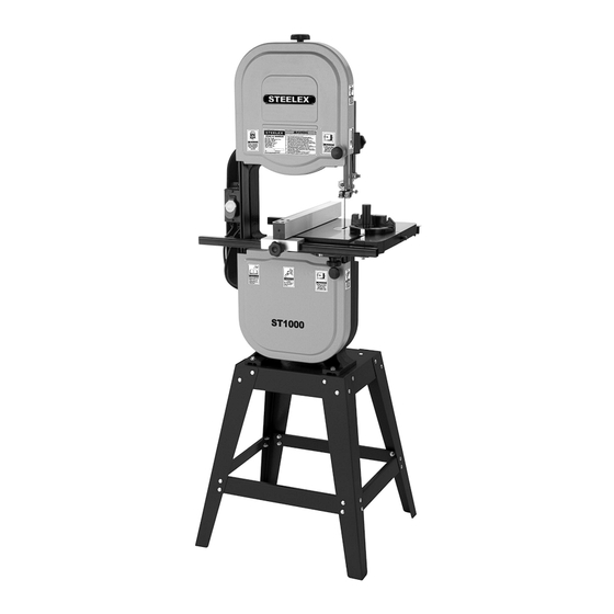
MODEL ST1000
OWNER'S
14" BANDSAW
MANUAL
Phone: (360) 734-3482 • Online Technical Support: tech-support@shopfox.biz
COPYRIGHT © MAY, 2006 BY WOODSTOCK INTERNATIONAL, INC.
WARNING: NO PORTION OF THIS MANUAL MAY BE REPRODUCED IN ANY SHAPE OR FORM WITHOUT
THE WRITTEN APPROVAL OF WOODSTOCK INTERNATIONAL, INC.
#8302TR
Printed in Taiwan
Advertisement
Table of Contents

Subscribe to Our Youtube Channel
Related Manuals for Woodstock STEELEX ST1000


Summary of Contents for Woodstock STEELEX ST1000
- Page 1 14" BANDSAW MANUAL Phone: (360) 734-3482 • Online Technical Support: tech-support@shopfox.biz COPYRIGHT © MAY, 2006 BY WOODSTOCK INTERNATIONAL, INC. WARNING: NO PORTION OF THIS MANUAL MAY BE REPRODUCED IN ANY SHAPE OR FORM WITHOUT THE WRITTEN APPROVAL OF WOODSTOCK INTERNATIONAL, INC.
- Page 2 ���������������������������������������������������������������������������������������������� ��������������������������������������� �������� ��� ������ ����������� ���� ������� ���� ������������� ������ ��� ����� ������� ���� ������� ��� ����������������������������������������������������������������������� ������������������������������������������������������������������������������������������������ ������������������������������������������������������������������������������������������������� ������ ��������������� ������� ����������� ���� ������������� ������� ������������� ���� ��������������� ������������ ��� ������� ��������� ������������� ����������� ���� ���� ������ ��� ������������������������������...
-
Page 3: Table Of Contents
Table of Contents MODEL ST1000 SPECIFICATIONS ......2 OPERATIONS ............23 MACHINE FEATURES ..........3 Operation Safety ............23 SAFETY ..............4 Overview ...............23 Safety Instructions ............4 Key Switch ..............24 POWER REQUIREMENTS ........6 Guide Post ..............24 Operation ................ 6 Blade Lead ..............25 SETUP .............. -
Page 4: Model St1000 Specifications
MODEL ST1000 SPECIFICATIONS Product Dimensions: Weight ............................................. 154 lbs. Length/Width/Height ..................................27" x 26" x 67 ⁄ " Footprint (Length/Width) ....................................24" x 22" Shipping Dimensions: Type ............................................. Cardboard Content ..........................................Machine Weight ............................................165 lbs. Length/Width/Height .................................. 45"L x 20"W x 15"H Motor: Type........................ -
Page 5: Machine Features
MACHINE FEATURES The instructions in this manual will be easier to understand if you become familiar with the location and names of the basic features of your new machine. Match up the feature list below with the letters in Figures 1 & 2 to identify the external bandsaw feature locations. -
Page 6: Safety
SAFETY Zero Risk Does Not Exist As with any human activity, zero risk from using machinery does not exist and cannot be attained. Operating this machine, as well as any machine, can be dangerous or relatively safe depending on the condition of the machine and the operator's experience, common sense, working conditions, and use of personal protective equipment (e.g., safety glasses, respirators, etc). - Page 7 Safety Instructions MENTAL ALERTNESS. Operating this machine 14. BLADE CONDITION. Dull or damaged blades when not fully alert greatly increases the require more effort to use, are difficult to con- risk of accidental injury. Never operate when trol, and increase the risk of injury. Sharpen under the influence of drugs/alcohol, when or replace blades when they become dull or tired, or otherwise distracted.
-
Page 8: Power Requirements
POWER REQUIREMENTS Operation Electrocution or fire could result if this machine is not grounded correctly or if Serious personal injury could occur if you con- your electrical configura- nect the machine to the power source before tion does not comply with you have completed the set up process. -
Page 9: Setup
SETUP Items Needed for Setup This machine presents serious injury hazards to untrained users. Read The following items are needed to complete the set through this entire manual up process, but are not included with your machine: to become familiar with the controls and opera- DESCRIPTION tions before starting the... -
Page 10: Inventory
Inventory After all the parts have been removed from the two boxes, you should have the following items: Main Inventory (Figure 4) A. Body Assembly ............1 Miter Gauge ..............1 Table ................1 D. Trunnion Support Bracket ........1 Motor with Pulley &... -
Page 11: Cleanup
Cleanup Site Considerations Floor Load The unpainted surfaces are coated with a waxy oil to protect them from corrosion during shipment. The Model ST1000 weighs 154 lbs. and has a base Remove this protective coating with a solvent clean- footprint of 24" W x 22" D. er or citrus-based degreaser. -
Page 12: Assembling Stand
Assembling Stand Main Body Components and Hardware Needed: Components and Hardware Needed: Carriage Bolts M8-1.25 x 16 ..........34 Body Assembly ..............1 Hex Nuts M8-1.25 ...............34 Hex Bolts M8-1.25 x 35 ............4 Base Plate ................1 Hex Nuts M8-1.25 ..............4 Legs ................... -
Page 13: Motor & Switch
Motor & Switch Place the V-belt on the pulley, move the motor to the left with moderate pressure, and tighten the cap screws. Components and Hardware Needed: Motor ..................1 Push the belt with moderate pressure. If the belt Switch ..................1 ", repeat Step 3. -
Page 14: Installing Blade Guides
Installing Blade To install the upper blade guide assembly: Guides Slide the upper guide assembly onto the guide post until the bottom of the guide post is flush with the bottom of the blade guide post hous- Components and Hardware Needed: ing (Figure 13) and secure with an M6-1 x 16 Upper Guide Assembly ............ -
Page 15: Table
Table Installing Positive Stop Components and Hardware Needed: Trunnion Support Bracket ..........1 Components and Hardware Needed: Table ..................1 Hex Bolt M8-1.25 x 80 ............1 Hex Bolts M8-1.25 x 30 ............2 Hex Nut M8-1.25 ..............1 Lock Washers 8mm .............. 2 Knobs M10-1.5 .............. -
Page 16: Installing Fence
Installing Fence Set the fence on the fence rail to the left of the blade. Components and Hardware Needed: Secure the fence with the M10-1.5 x 25 knob Fence Body ................1 (Figure 18). Front Angled Rail ..............1 Front Square Rail ..............1 Rear Rail ................... -
Page 17: Dust Collection
Dust Collection Adjusting Positive Stop The positive stop allows the table to be reset 90˚ to DO NOT operate the Model ST1000 without an the blade after tilting to the right. adequate dust collection system. This saw cre- ates substantial amounts of wood dust while To set the positive stop: operating. -
Page 18: Blade Tracking
Blade Tracking Blade Centered The blade tracking is primarily affected by the tilt of on Peak of Crown the upper wheel, also known as Center Tracking; and the alignment of both wheels, also known as Blade Coplanar Tracking. (For Coplanar Tracking, see the Centered Wheel Alignment instructions on Page 37.) on Wheel... -
Page 19: Test Run
Test Run Tensioning Blade A properly tensioned blade is essential for making Once the assembly is complete and you have read accurate cuts and is a prerequisite before making through Safety section, test run the machine before many bandsaw adjustments. continuing with the setup. -
Page 20: Adjusting Support Bearings
Adjusting Support Look at the face of the support bearing and rotate the blade guide assembly side-to-side, Bearings until the blade is perpendicular with the face of the support bearing as illustrated in Figure 23. The support bearings are positioned behind the blade and support the back of the blade during cut- ting operations. -
Page 21: Adjusting Blade Guides
Adjusting Blade Note: For a quick gauge, fold a dollar bill in half twice (four thicknesses of a dollar bill is approxi- Guides mately 0.016") and place it between the support bearing and the blade as shown in Figure 25. The blade guides provide side-to-side support to help keep the blade straight while cutting. -
Page 22: Calibrating Table Tilt Scale
Calibrating Table Tilt Move the guides forward or backward to posi- tion them laterally, so that the edges of the Scale blocks are " behind the blade gullets as illus- trated in Figure 27. The pointer on the table tilt scale must be calibrated in order for the scale reading to be accurate. -
Page 23: Aligning Table
Aligning Table Aligning Fence To ensure cutting accuracy when the table is first To ensure cutting accuracy when the fence is first installed, the table should be aligned so that the installed, the fence should be aligned with the miter miter slot is parallel to the bandsaw blade. -
Page 24: Miter Gauge
Miter Gauge Loosen the lock knob on the miter gauge and adjust it flush with the edge of the square. The miter gauge needs to be calibrated to the blade Tighten the lock knob, and verify the setting. when it is first mounted in the miter slot. Refer to the Blade Lead section on Page 25 for more informa- Note: Sometimes the tightening procedure can tion about typical bandsaw cutting habits. -
Page 25: Operations
OPERATIONS Overview Operation Safety The bandsaw is one of the most versatile wood cut- ting tools in the shop. It is capable of performing many different cutting functions including: Damage to your eyes, lungs, and ears could result from using this machine without proper Straight Cuts protective gear. -
Page 26: Key Switch
Key Switch Guide Post The guide post (shown in Figure 32) connects the The Model ST1000 features a removable key (Figure upper blade guide assembly to the bandsaw. The 31) to disable the ON/OFF switch. This feature is function of the guidepost is to allow the blade guide handy for preventing unexpected start-up or keeping assembly to move up or down depending on the unauthorized persons from operating the machine. -
Page 27: Blade Lead
Blade Lead Skew the fence so it is parallel to the edge of the scrap piece. You may need to re-adjust the fence locking mechanisms to gain maximum It is common for a bandsaw blade to wander off the adjustment. cut line when sawing as shown in Figure 33. -
Page 28: Ripping
Ripping Crosscutting Crosscutting is the process of cutting across the Ripping is the process of cutting with the grain of the grain of wood. For plywood and other processed wood stock. For plywood and other processed wood, wood, crosscutting simply means cutting across the ripping simply means cutting down the length of width of the material. -
Page 29: Resawing
Resawing To resaw a workpiece: Verify that the bandsaw is setup properly and Resawing (Figure 36) is the process of cutting a that the table is perpendicular to the blade. board into two or more thinner boards. The maxi- mum board width that can be resawn is limited Use the widest blade your bandsaw will accept. -
Page 30: Cutting Curves
Cutting Curves Stacked Cuts Bandsaws have the ability to cut multiple copies of a When cutting curves, simultaneously feed and turn particular shape by stacking workpieces together. the stock carefully so that the blade follows the layout line without twisting. If a curve is so abrupt Before making stacked cuts, ensure that both the that it is necessary to repeatedly back up and cut a table and the blade are properly adjusted to 90°. -
Page 31: Blade Information
Blade Information • Straight Cutting—Use the largest width blade that you own. The Model ST1000 will accept blades up to ⁄ " wide. Narrow blades can cut Selecting the right blade requires a combination of tight curves (a small radius) but are not very the various blade characteristics mentioned below, good at cutting straight lines because they natu- the type of material you plan to cut, and the type of... -
Page 32: Blade Breakage
Blade Breakage • Hook—The teeth on this style have a positive angle (downward) which makes them dig into Many conditions may cause a bandsaw blade to the material, and the gullets are usually rounded break. Blade breakage is unavoidable, in some cases, for easier waste removal. -
Page 33: Blade Changes
Blade Changes To replace the blade: Put on heavy leather gloves. Slide the blade through the table slot, ensuring Always disconnect power that the teeth are pointing down toward the to the machine when table. Note: If the teeth will not point downward changing blades. -
Page 34: Maintenance
MAINTENANCE Cleaning Always disconnect power Cleaning the Model ST1000 is relatively easy. Vacuum to the machine before excess wood chips and sawdust, and wipe off the performing maintenance. remaining dust with a dry cloth. If any resin has built Failure to do this may result up, use a resin dissolving cleaner to remove it. -
Page 35: Service
SERVICE Troubleshooting This section covers the most common problems and corrections with this type of machine. WARNING! DO NOT make any adjustments until power is disconnected and moving parts have come to a complete stop! Motor PROBLEM POSSIBLE CAUSE CORRECTIVE ACTION Machine does not start 1. - Page 36 Operation PROBLEM POSSIBLE CAUSE CORRECTIVE ACTION Blade slows when cut- 1. V-belts loose. 1. Tighten V-belts. ting. Blade makes a 2. V-belts worn out. 2. Replace V-belts. squealing noise, espe- cially on start-up. Blade does not run 1. Tracking is not adjusted properly. 1.
-
Page 37: Checking V-Belt
Checking V-Belt Tensioning V-Belt To ensure optimum power transmission from the Tools Needed: motor to the blade, the V-belt must be in good con- Hex Wrench 6mm ..............1 dition and operate under proper tension. The belts Wrench 13mm ................ 1 should be checked for cracks, fraying, and wear. -
Page 38: Replacing V-Belt
Replacing V-Belt Slip the old V-belt off of the wheel pulley and install the new V-belt in its place. Tools Needed: Install the lower wheel back onto the bear- Hex Wrench 6mm ..............1 ing shaft and replace/tighten the wheel mount Wrench 13mm ................ -
Page 39: Wheel Alignment
Wheel Alignment If your wheels are not coplanar, check them for adjustment by placing the straightedge on the lower wheel first, ensuring that it touches both Wheel alignment is one of the easiest ways to ensure the top and bottom of the rim, and adjust the you get optimal performance from your bandsaw. - Page 40 Remove the blade from the saw, then remove To Shim a Wheel: the securing nut and the washers from the wheel that needs to be shimmed. Take the Adjust the tracking knob so that the top wheel wheel off. is parallel with the bottom wheel. With the straightedge touching both points of the wheel Electrical washers work well for shimming that does not need to be adjusted (Figure 45),...
-
Page 41: St1000 Electrical Components
ST1000 Electrical Components 110V Motor Wiring 220V Motor Wiring -39- ST1000 14" Bandsaw... -
Page 42: St1000 Wiring Diagram
ST1000 Wiring Diagram ������������������� ������������� �������������������� � � � � ��� ��� ����� ������ ����� ������� ��������� ����� ��� �������� ������������� �������������������� � � � � ��� ��� ����� ������ ����� ��� ����� ��������� ��� ���������������� -40- ST1000 14" Bandsaw... -
Page 43: Main Breakdown
Main Breakdown -41- ST1000 14" Bandsaw... -
Page 44: Main Breakdown Parts List
Main Breakdown Parts List PART # DESCRIPTION PART # DESCRIPTION XST1000001 MOTOR 3/4HP 110/220V XPHTEK4M TAP SCREW M4 X 8 XST1000001-1 FAN COVER XST1000049 COVER UPPER FRONT XST1000001-2 XST1000050 SAW BLADE 6TPI X 93-1/2” XST1000001-3 CAPACITOR COVER XST1000051 COVER UPPER BACK XPC200 CAPACITOR 200 MFD, 125 V XPFS01M... - Page 45 Main Breakdown Parts List PART # DESCRIPTION PART # DESCRIPTION XST1000100 KNOB M10-1.5 XPS08M PHLP HD SCR M5-.8 X 12 XPB73M HEX BOLT M10-1.5 X 50 XPB83M HEX BOLT M6 -1 X 16 XPB82M HEX BOLT M8-1.25 X 80 XST1000115 TENSION POINTER XPN03M HEX NUT M8-1.25...
-
Page 46: Fence Breakdown & Parts List
Fence Breakdown & Parts List ��� ��� ��� ��� ��� ��� ��� ��� ��� ��� ��� ��� ��� ��� ��� ��� ��� ��� ��� ��� ��� ��� ��� ��� ��� ��� PART # DESCRIPTION XPB04M HEX BOLT M6-1 X 10 XPB08M HEX BOLT M6-1 X 20 XPLW03M... -
Page 47: Safety Labels Breakdown & Parts List
The owner of this machine MUST maintain the original location and readability of all labels on this machine. If any label is removed or becomes unreadable, REPLACE that label before allowing the machine to enter service again. Contact Woodstock International, Inc. at (360) 734-3482 or www. shopfoxtools.com to order new labels. -
Page 48: Warranty
International, Inc. reasonable opportunity to verify the alleged defect through inspection. If it is determined there is no defect, or that the defect resulted from causes not within the scope of Woodstock International Inc.'s warranty, then the original owner must bear the cost of storing and returning the product. -
Page 49: Warranty Registration
Warranty Registration Name _______________________________________________________________________________________ Street _______________________________________________________________________________________ City __________________________ State _____________________________Zip _________________________ Phone # _______________________ Email ____________________________Invoice # ____________________ Model #_________Serial #______________Dealer Name__________________Purchase Date___________ The following information is given on a voluntary basis. It will be used for marketing purposes to help us develop better products and services. - Page 50 FOLD ALONG DOTTED LINE Place Stamp Here WOODSTOCK INTERNATIONAL INC. P.O. BOX 2309 BELLINGHAM, WA 98227-2309 FOLD ALONG DOTTED LINE TAPE ALONG EDGES--PLEASE DO NOT STAPLE...
Need help?
Do you have a question about the STEELEX ST1000 and is the answer not in the manual?
Questions and answers