Table of Contents
Advertisement
Quick Links
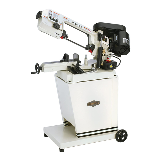
MODEL M1013
5" x 6" METAL CUTTING
BANDSAW
OWNER'S MANUAL
(FOR MODELS MANUFACTURED SINCE 6/09)
Phone: (360) 734-3482 • Online Technical Support: tech-support@shopfox.biz
COPYRIGHT © JANUARY, 2005 BY WOODSTOCK INTERNATIONAL, INC., REVISED SEPTEMBER, 2009 (TS)
WARNING: NO PORTION OF THIS MANUAL MAY BE REPRODUCED IN ANY SHAPE OR FORM WITHOUT
THE WRITTEN APPROVAL OF WOODSTOCK INTERNATIONAL, INC.
Printed in China
#6731CR
Advertisement
Table of Contents

Related Manuals for Shop fox SHOP FOX M1013


Summary of Contents for Shop fox SHOP FOX M1013
- Page 1 MODEL M1013 5" x 6" METAL CUTTING BANDSAW OWNER'S MANUAL (FOR MODELS MANUFACTURED SINCE 6/09) Phone: (360) 734-3482 • Online Technical Support: tech-support@shopfox.biz COPYRIGHT © JANUARY, 2005 BY WOODSTOCK INTERNATIONAL, INC., REVISED SEPTEMBER, 2009 (TS) WARNING: NO PORTION OF THIS MANUAL MAY BE REPRODUCED IN ANY SHAPE OR FORM WITHOUT THE WRITTEN APPROVAL OF WOODSTOCK INTERNATIONAL, INC. Printed in China #6731CR...
- Page 2 This manual provides critical safety instructions on the proper setup, operation, maintenance and service of this machine/equipment. Failure to read, understand and follow the instructions given in this manual may result in serious personal injury, including amputation, electrocution or death. The owner of this machine/equipment is solely responsible for its safe use.
-
Page 3: Table Of Contents
Contents INTRODUCTION ........2 MAINTENANCE ........26 Woodstock Technical Support ....2 General .......... 26 Machine Specifications ......3 Cleaning ......... 26 Lubrication ........26 SAFETY ..........6 SERVICE ..........27 Standard Machinery Safety ..... 6 Additional Safety for General .......... 27 Metal Cutting Bandsaws ...... -
Page 4: Introduction
Woodstock International, Inc. is committed to customer satisfaction. Our intent with this manual is to include the basic information for safety, setup, operation, maintenance, and service of this product. -
Page 5: Machine Specifications
M1013 Owner's Manual (Mfg. Since 6/09) MACHINE SPECIFICATIONS Phone #: (360) 734-3482 • Online Tech Support: tech-support@shopfox.biz • Web: www.shopfox.biz MOdEl M1013 5" X 6" METAl CUTTING BANdSAW Motor Type ..................TEFC Capacitor Start Induction Horsepower ....................... ⁄ Voltage ........................ 110/220V Prewired ........................ - Page 6 M1013 Owner's Manual (Mfg. Since 6/09) Overall Dimensions Weight ........................150 lbs. Length ......................... 39" Width ........................23 ⁄ " Height ........................54 ⁄ " Foot Print (Length/Width) ..................26 ⁄ " x 20 ⁄ " Construction Materials Table ....................Precision-Ground Cast Iron Wheels .....................
-
Page 7: Controls And Features
M1013 Owner's Manual (Mfg. Since 6/09) Controls and Features Blade Tension Knob Blade Tension Gauge Pulley Cover Gearbox Heavy-Duty Motor Blade Guide Knob Blade Guides Hydraulic Cylinder & Feed Rate Dial Vise Clamp Handwheel ON/OFF Push-Button Switch Assembly Cast Iron Stop Table Angle Scale Figure 1. -
Page 8: Safety
M1013 Owner's Manual (Mfg. Since 6/09) Standard SAFETY SAFETY Machinery Safety READ MANUAL BEFORE OPERATING MACHINE. FAILURE TO FOLLOW INSTRUCTIONS BELOW WILL RESULT IN PERSONAL INJURY. Indicates an imminently hazardous situation which, if not avoided, WILL result in death or serious injury. Indicates a potentially hazardous situation which, if not avoided, COULD result in death or serious injury. - Page 9 M1013 Owner's Manual (Mfg. Since 6/09) 10. NEVER LEAVE WHEN MACHINE IS RUNNING. Turn power OFF and allow all moving parts to come to a complete stop before leaving machine unattended. 11. DO NOT USE IN DANGEROUS ENVIRONMENTS. DO NOT use machinery in damp, wet locations, or where any flammable or noxious fumes may exist.
-
Page 10: Additional Safety For Metal Cutting Bandsaws
M1013 Owner's Manual (Mfg. Since 6/09) Additional Safety for Metal Cutting Bandsaws READ and understand this USE this and other machinery with caution entire manual before using and respect. Always consider safety first, this machine. Serious per- as it applies to your individual working sonal injury may occur conditions. -
Page 11: Electrical
M1013 Owner's Manual (Mfg. Since 6/09) ELECTRICAL The machine must be properly set up before it is safe to operate. DO NOT connect this machine to the power source until instructed to do so in the "Test Run" portion of this manual. 110V/220V Operation The Model M1013 is prewired for 110V operation. -
Page 12: Setup
M1013 Owner's Manual (Mfg. Since 6/09) SETUP Unpacking Belt Cover .........1 K. Work Stop ........1 L. Work Stop Shaft ......1 This machine has been carefully packaged for safe M. Wheels ........2 transportation. If you notice the machine has been damaged during shipping, please contact your authorized Assembly Hardware (Not Shown): Shop Fox dealer immediately. -
Page 13: Machine Placement
M1013 Owner's Manual (Mfg. Since 6/09) Machine Placement Cleaning Machine • Floor Load: This machine distributes a The table and other unpainted parts of your heavy load in a small footprint. Some metal cutting bandsaw are coated with a waxy grease that protects them from corrosion during residential floors may require additional shipment. -
Page 14: Wheels, Feet, And Cabinet
M1013 Owner's Manual (Mfg. Since 6/09) Wheels, Feet, and Cabinet This bandsaw is shipped with four rubber feet with posts and two wheels with an axle. It is your option to install four rubber feet if you do not need to move the bandsaw, or install the axle and wheels if you need to move the bandsaw regularly. - Page 15 M1013 Owner's Manual (Mfg. Since 6/09) 8. Position the right panel between the front and rear panel, and secure it in place with six M8-1.25 x 16 hex bolts, twelve 8mm flat washers, and six M8-1.25 hex nuts (see Figure 7). The Model M1013 is heavy! To avoid personal injury, get help to lift this machine.
-
Page 16: Shipping Strap Removal & Stop Adjustment
M1013 Owner's Manual (Mfg. Since 6/09) Shipping Strap Removal & Stop Adjustment To ensure that your bandsaw arrives without damage to the hinge system, a shipping strap was installed. After removing the shipping strap, you will have to make a Shipping Brace series of adjustments, beginning with the feed stop bolt. -
Page 17: Chip Tray & Cast Iron Stop
M1013 Owner's Manual (Mfg. Since 6/09) Chip Tray & Cast Iron Stop The chip tray directs small workpieces into a bucket when the cut is complete. The cast iron stop allows you to repeat cuts at the same length. To install the chip tray and cast iron stop, do these steps: 1. -
Page 18: Automatic Off Adjustment
M1013 Owner's Manual (Mfg. Since 6/09) Automatic OFF Adjustment After you have removed the shipping strap and have adjusted the headstock stop bolt, you must adjust the OFF button lever stop bolt, so the bandsaw shuts OFF automatically when a cut is complete. Stop Bolt &... -
Page 19: Pulley Cover
M1013 Owner's Manual (Mfg. Since 6/09) Pulley Cover When opened, the pulley cover gives you access to change the pulley ratio so the bandsaw can cut at one of three speeds. ENTANGLEMENT HAZARD! MAKE SURE bandsaw unplugged before proceeding! Otherwise, severe injury may occur. -
Page 20: Blade Tension
M1013 Owner's Manual (Mfg. Since 6/09) Blade Tension Proper blade tension is essential to long blade life, straight cuts, and efficient cutting. Cylinder Two major signs that you do not have proper blade Lock Pin tension are: 1) the blade stalls in the cut and slips on the wheels, and 2) the blade frequently breaks from being too Safety tight. -
Page 21: Blade Guides
M1013 Owner's Manual (Mfg. Since 6/09) Blade Guides The blade guide side bearings support and twist the Blade Guide Support Bearing Guide blade straight so the blade will enter the workpiece Bearing perpendicular to the table surface (see Figure 21). The Adjustment blade guide support bearings prevent blade twist by Hex Bolt... -
Page 22: Test Run
M1013 Owner's Manual (Mfg. Since 6/09) Test Run Once the assembly is complete, test run your machine to make sure it runs properly. If, during the test run, you cannot easily locate the source of an unusual noise or vibration, stop using the machine immediately, then review the Troubleshooting on Page 32. -
Page 23: Operations
M1013 Owner's Manual (Mfg. Since 6/09) OPERATIONS General This machine will perform many types of operations that are beyond the scope of this manual. Many of these operations can be dangerous or deadly if performed incorrectly. The instructions in this section are written with the understanding that the operator has the necessary knowledge and skills to operate this machine. - Page 24 M1013 Owner's Manual (Mfg. Since 6/09) 5. Adjust the cast iron stop for duplicate cuts and Lock Lever install the ejector chute if required. 6. Loosen the headstock lock lever (Figure 24), and swivel the headstock to the needed angle of cut, and lock the lever in place.
-
Page 25: Blade Speed
M1013 Owner's Manual (Mfg. Since 6/09) Blade Speed The Model M1013 has these three blade speeds: 80, 120, Note: These suggested blade speeds and 200 FPM. are an average for both High Carbon Blades and Bimetal Blades. To change blade speeds, do these steps: Refer to your saw blade manufac- turer for exact speeds. -
Page 26: Blade Selection
M1013 Owner's Manual (Mfg. Since 6/09) Blade Selection The chart below is a basic starting point for To select the correct blade TPI, do these choosing blade type based on teeth per inch steps: (TPI) for variable tooth pitch blades and for standard raker type bimetal blades/HSS blades. -
Page 27: Feed Rate
M1013 Owner's Manual (Mfg. Since 6/09) Feed Rate The speed at which the saw blade will cut through a workpiece is controlled by blade type and feed rate. The feed rate is controlled by the valve lever and feed rate dial on the hydraulic cylinder shown in Figure 27. Feed Rate Dial Turning the valve lever in-line with the piping, as shown... -
Page 28: Maintenance
M1013 Owner's Manual (Mfg. Since 6/09) MAINTENANCE General Regular periodic maintenance on your machine will ensure its optimum performance. Make a habit of inspecting your machine each time you use it. Check for the following conditions and repair or replace when necessary: •... -
Page 29: Service
If you require additional machine service not included in this section, please contact Woodstock International Technical Support at (360) 734-3482 or send e-mail to: tech-support@shopfox.biz. MAKE SURE that your machine is... - Page 30 M1013 Owner's Manual (Mfg. Since 6/09) 4. Loosen the tension knob and slip the blade off of the wheels. 5. Install the new blade through both blade guide bearings and around the bottom wheel (see the example in Figure 33). 6.
-
Page 31: Blade Tracking
M1013 Owner's Manual (Mfg. Since 6/09) Blade Tracking The blade tracking has been properly set at the factory. The tracking will rarely need to be adjusted if the Blade bandsaw is used properly. Tension Knob To adjust the blade tracking on the bandsaw, do these steps: Hex Bolts 1. -
Page 32: Electrical Safety Instructions
These pages are current at the time of printing. However, in the spirit of improvement, we may make changes to the electrical systems of future machines. Study this diagram carefully. If you notice differences between your machine and these wiring diagrams, call Woodstock International Technical Support at (360) 734-3482. -
Page 33: Wiring Diagram
wiring diagram M1013 Owner's Manual (Mfg. Since 6/09) Wiring Diagram Read Page 30 STOP Before Wiring 110V 110V 110V Power Supply Power Supply Connection Bandsaw Motor Bandsaw Motor Capacitor Cover Capacitor Cover Green Green Black Black Wire number Wire number Wire Color Wire Color White... -
Page 34: Troubleshooting
M1013 Owner's Manual (Mfg. Since 6/09) Troubleshooting This section covers the most common problems and corrections with this type of machine. WARNING! DO NOT make any adjustments until power is disconnected and moving parts have come to a complete stop! PROBLEM POSSIBLE CAUSE CORRECTIVE ACTION... - Page 35 M1013 Owner's Manual (Mfg. Since 6/09) PROBLEM POSSIBLE CAUSE CORRECTIVE ACTION Blades break often. 1. Blade is not tensioned correctly. 1. Check to see that blade is not excessively tight or too loose. 2. The workpiece is loose in the vise. 2.
-
Page 36: Parts
M1013 Owner's Manual (Mfg. Since 6/09) PARTS Motor & Feed Rate Control -34-... - Page 37 M1013 Owner's Manual (Mfg. Since 6/09) Motor & Feed Rate Control Parts List REF PART # DESCRIPTION REF PART # DESCRIPTION XM1013001 MOTOR 1/2HP 110/220V 1PH XPN08 HEX NUT 3/8-16 XM1013001-1 MOTOR FAN COVER XM1013018 BRACKET XM1013001-2 MOTOR FAN XM1013019 HANDLE XM1013001-3 CAPACITOR COVER XPCAP97...
-
Page 38: Saw Assembly
M1013 Owner's Manual (Mfg. Since 6/09) Saw Assembly See Page 40 See Page 40 114 113 145A See Page 40 See Page 40 162A See Page 40 -36-... - Page 39 M1013 Owner's Manual (Mfg. Since 6/09) Saw Assembly Parts List PART # DESCRIPTION PART # DESCRIPTION XM1013100 BODY FRAME XPN02 HEX NUT 5/16-18 XPB41 HEX BOLT 1/2-12 X 1-1/2 XM1013134 MOTOR MOUNT PLATE XM1013104 GEAR BOX GASKET XM1013135 KNOB BOLT 5/16-18 X 1-3/4 XM1013105 PLATE XPB07...
-
Page 40: Stand Assembly
M1013 Owner's Manual (Mfg. Since 6/09) Stand Assembly 233A 234 235 232A 229A 228A 223A 214-6 218-1 218-1 -38-... - Page 41 M1013 Owner's Manual (Mfg. Since 6/09) Stand Assembly Parts List PART # DESCRIPTION PART # DESCRIPTION XM1013200 BASE XM1013220 PLATE XPB26M HEX BOLT M8-1.25 X 30 XPCAP30 CAP SCREW 5/16-18 X 1/2 XPLW04M LOCK WASHER 8MM XPS04 PHLP HD SCR 1/4-20 X 1/2 XM1013204 SCALE 223A XM1013223A...
-
Page 42: Guides & Shafts
guides and shafts M1013 Owner's Manual (Mfg. Since 6/09) Guides & Shafts 303V2 302V2 301V2 300V2 -40-... - Page 43 M1013 Owner's Manual (Mfg. Since 6/09) Guides & Shafts Parts List PART # DESCRIPTION PART # DESCRIPTION 300V2 XM1013300V2 REAR BLADE WHEEL V2.06.09 XPLW04 LOCK WASHER 3/8 301V2 XM1013301V2 BUSHING V2.06.09 XM1013319 WORM GEAR SHAFT 302V2 XM1013302V2 BLADE WHEEL SHAFT V2.06.09 XM1013322 SPECIAL PIN 10 X 40MM 303V2 XM1013303V2 AXLE BLOCK V2.06.09...
-
Page 44: Machine Labels
MUST maintain the original location and readability of all labels on this machine. If any label is removed or becomes unreadable, REPLACE that label before allowing the machine to enter service again. Contact Woodstock International, Inc. at (360) 734-3482 or www. shopfoxtools.com to order new labels. - Page 45 M1013 Owner's Manual (Mfg. Since 6/09)
- Page 46 Fold along dotted lIne place stamp Here Woodstock international inc. p.o. box 2309 bellingham, Wa 98227-2309 Fold along dotted lIne tape along edges--please do not staple...
-
Page 47: Warranty
Woodstock International, Inc. will repair or replace, at its expense and at its option, the Shop Fox machine or machine part, which in normal use has proven to be defective, provided that the original owner returns the product prepaid to a Shop Fox factory service center with proof of their purchase of the product within two years, and provides Woodstock International, Inc. - Page 48 High Quality Machines and Tools Woodstock International, Inc. carries thousands of products designed to meet the needs of today's woodworkers and metalworkers. Ask your dealer about these fine products:...